Table of Contents
Advertisement
Quick Links
TOYOTA COMPUTERIZED EMBROIDERY SYSTEM
INSTRUCTION MANUAL
Before using the embroidery machine, please read through this manual
carefully for proper use of the machine.
After reading the manual, keep it at a safe place near the machine so
that you can consult it whenever it is necessary.
When you turn over the machine to somebody, make sure to attach this
manual to the machine.
Since this is a business use machine, it should be operated by operators
who are well versed in the basic operations.
Advertisement
Table of Contents

Related Manuals for Toyota Expert EPS9000


Summary of Contents for Toyota Expert EPS9000
-
Page 1: Instruction Manual
TOYOTA COMPUTERIZED EMBROIDERY SYSTEM INSTRUCTION MANUAL Before using the embroidery machine, please read through this manual carefully for proper use of the machine. After reading the manual, keep it at a safe place near the machine so that you can consult it whenever it is necessary. -
Page 3: Table Of Contents
CONTENTS SAFETY PRECAUTIONS (Make sure to read the following before use) - - - - - - - - - - - - - - - - 4 PART NAMES CHECKING THE PARTS - - - - - - - - - - - - - - - - - - - - - - - 8 ACCESSORIES - - - - - - - - - - - - - - - - - - - - - - - - - - - - - 9 AMC335: FLOPPY DISK DRIVE (TO BE PURCHASED SEPARATELY) - - - - - - - - - - - - 10... -
Page 4: Safety Precautions
SAFETY PRECAUTIONS Safety precautions are provided to prevent risks and losses which could result from incorrect handling. Please read carefully and comply strictly with them. Meaning of " DANGER", " Indicates there could be imminent risk of situation resulting in fatal or serious injury DANGER from incorrect handling. - Page 5 If water or oils enter the electric/electronic units, shut off the power by the power switch, shut off the source of power supply and contact your TOYOTA dealer. When disconnecting the power cord from the receptacle, pull the cord while holding the plug.
- Page 6 CAUTION Do not use the machine in areas where strong electric field or magnetic field is generated by a high-power high-frequency motor generator or high-frequency welder. Otherwise the machine will malfunction to cause injury or machine trouble. Place the machine on a sturdy base. Otherwise the machine may fall to cause injury or machine trouble.
-
Page 7: Positions And Contents Of The Warning Labels
Positions and Contents of the Warning Labels CAUTION ATTENTION Fingers might be injured. Do not put your hand on hoop while in motion. Do not put your finger or hand inside thread tension cover or guard cover. Les doigts peuvent être blessés. Ne pas mettre la main sur le cercle à... -
Page 8: Part Names
PART NAMES CHECKING THE PARTS After unpacking the machine, check to be sure that all of the items below have been delivered. ● Embroidery machine (1 set) ● Thread guide (1 pc.) ● Power supply box (1 pc.) DC power supply connector Power switch AC power supply connector ●... -
Page 9: Accessories
ACCESSORIES Instruction manual Parts catalogue ● ● (1 copy) (1 copy) (This book) INSTRUCTION PARTS MANUAL CATALOGUE ● Tools (2) Aluminum bobbin 2 pcs. (1) Needle (#11) 10 pcs. (5) Minus screwdriver (small) (6) Offset screwdriver 1 pc. 1 pc. (9) Small pincers 1 pc. -
Page 10: Amc335: Floppy Disk Drive (To Be Purchased Separately)
AMC335: FLOPPY DISK DRIVE (TO BE PURCHASED SEPARATELY) ● FDD (floppy disk drive) and FDD connection cable Various kinds of embroidery hoop are available. Consult your TOYOTA dealer for details. -
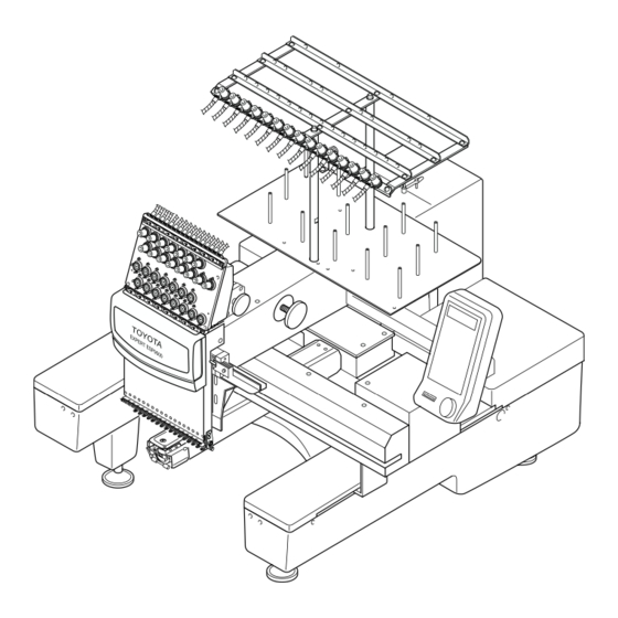
Page 11: Embroidery Machine
EMBROIDERY MACHINE Thread guide Sub thread tension regulator Spiral tube Thread tension regulator Tension base Operation panel box (For details, refer to Page 12.) Color change motor Take-up lever Thread take-up cover Thread hook motor Jump motor Needle bar case X/Y-axis drive system Needle plate Table... -
Page 12: Operation Panel Box
OPERATION PANEL BOX Function menu key Ten keys (numeric keys) :Used for a needle bar number of 10 or larger Trace key Hoop forward key Offset key Forward/Back unit selection key Thread trimming Hoop back key Stop key Start key SLOW Speed adjusting switch FD07... -
Page 13: Dip Switches
In the test mode, you can access to the following information: ● Accumulated number of embroidered pieces of cloth ● Accumulated number of stitches ● Accumulated number of error displays and others Consult your TOYOTA dealer for more details. Two-way communica- tions − −... -
Page 14: Preparation
PREPARATION ASSEMBLING ● Attaching the thread guide Stand the thread stand shafts (1) (2 pcs. in total) on the thread stand plate (2) perpendicu- lar to it by screwing in the shaft at positions A and B on the plate (2). Securely tighten the thread stand shafts (1) by the spanner set on the flats at the middle of the thread stand shaft (1) to fix them on the thread stand plate (2). -
Page 15: Carrying
CARRYING As shown in the illustration below, hold the machine at the positions indicated in the label by two or more per- sons to carry the machine. Machine holding position (indicated in the label) INSTALLATION Place the embroidery machine on a rugged base so that the table will be level. At this time, make sure to place attached vibration-preventive rubbers (H) under the adjuster foot (1). -
Page 16: Wiring
WIRING Make sure that the power switch (2) of the power supply box (1) is OFF. Insert the plug (4) of the DC power cord (3) securely into the power supply connector (5) of the embroidery machine. Insert the other plug (6) of the DC power cord (3) securely into the DC power supply connector (7) of the power supply box (1). -
Page 17: Connecting The Fdd (Floppy Disk Drive) (To Be Purchased Separately)
CONNECTING THE FDD (FLOPPY DISK DRIVE) (TO BE PURCHASED SEPARATELY) Insert the plug (2) of the FDD connection cable (1) securely into the FDD connector (3). Insert the plug (4) at the other end of the FDD connection cable (1) securely into the connector of the FDD. Embroidery machine FDD connection cable (1) -
Page 18: Setting The Upper Thread
SETTING THE UPPER THREAD Upper Thread Setting Fig. A Passing the Upper Thread: Procedure 1. Pass the thread from the spool (1) through the hole on the thread guide (1) just above the spool (1) and further pass it through thread guides at the mid- dle and front rows. - Page 19 Fig. B Passing the Upper Thread: Thread Guide to Needle Thread guide Tension base Needle bar case cover TOYOTA EXPER T ESP9 0 0 0 Needle bar case Sub thread tension regulator (15) Threader Thread guide (15)-1...
-
Page 20: Setting The Under Thread
SETTING THE UNDER THREAD Orient the bobbin (1) with its thread facing in the direction, specified by the arrow symbol, and put it in the bobbin case (2). Route the thread through the thread groove (3) in the bobbin case, under the thread tension spring (4) and the thread guard (5). -
Page 21: Setting The Fabric On The Hoop
SETTING THE FABRIC ON THE HOOP Place the fabric (2) on the outer hoop (1) and press the inner hoop (3) into the outer hoop (1). If the inner hoop (3) cannot be pressed into the outer hoop (1) smoothly, loosen the hoop set screw (4). Check if the fabric is correctly set in the hoop by pressing the center of the fabric gently with the finger as shown in the illustration below. -
Page 22: Setting The Hoop To The Embroidery Machine
SETTING THE HOOP TO THE EMBROIDERY MACHINE Attach two holder bases (1) to the joint plate (2) in the direction indicated by with screws (3). Determine the holder base (1) attaching position meeting the size of the hoop. Insert the right and left metallic tabs of the embroidery hoop set in the sections A and B in the direction of dashed line arrows and fix the tabs by engaging the hoop presser springs (4) of the holder bases (1) in the tabs. -
Page 23: Attaching The Table
ATTACHING THE TABLE Push in the table (1) till it hits the bottom with care to maintain equally at both right and left of top of the base cover (2) on the embroidery machine. Tighten the right and left fixing screws (3). This completes the attaching of the table. Fixing screw (3) Table (1) DIP SWITCH SETTING... -
Page 24: Winding The Under Thread
WINDING THE UNDER THREAD Set a bobbin (2) on the under thread winding shaft (1). Place the spool (3) on the spool stand on the cover, pass the thread end through the thread tension regulator guide (4) and wind the thread round the bobbin (2). Press the thread winder lever (5) to the right so that it touches the inner face of the bobbin (2). -
Page 25: Checkups Before Starting Operation
CHECKUPS BEFORE STARTING OPERATION Before starting the machine, carry out checkups as indicated below. Turn the main switch OFF before checking the machine prior to starting the operation. If you check the machine without turning the main switch OFF, you could sustain injury. Check Point Covers Thread... -
Page 26: Checking The Embroidery Head
CHECKING THE EMBROIDERY HEAD Check of the Color Change Device and Set Screw The color change device selects needle bars. The machine will fail to operate if the color change cam is off the prede- termined position (set screw is positioned right above or right below). Turn the handle of the color change device to bring the set screw to the top position. -
Page 27: Operation Procedure
OPERATION PROCEDURE 《 《 《 《 OPERATION BASICS》 》 》 》 STARTING AND STOPPING THE MACHINE Power Switch The power switch is provided on the power supply box. Press the power switch at "O" side to turn the power OFF or at "I" to turn the power ON. -
Page 28: Steps To Start Embrodiery
STEPS TO START EMBRODIERY Example: To input the hoop data using the flat hoop from FDD (floppy disk drive) (to be purchased separately) 1 Turn ON the power switch at the power supply box. 2 Select "FLAT" for "HOOP" using 3 Select "ON"... - Page 29 11 Input the needle numbers in the order of needle change using the numeric keys. 12 Press the SET key. * * * C O L O R C H A N G E * * * M O D E A U T O 0 1 / 0 4 : 13 The screen will display the information as shown below when the...
-
Page 30: Screens
SCREENS The LCD screen displays variety of information to navigate the operation. The information displayed on the LCD screen is briefly explained below. ● Basic Menu Hoop mode (FLAT / CAP / SLEEVE) Change the selection with the hoop travel keys Start point return motion and initializing at the power switch "ON"... - Page 31 ● Function Menu: Pressing Stitch / RPM Change the selection with the hoop travel keys Thread breakage sensor (OFF / 1 - 5) Change the selection with the hoop travel keys Press the SET key * Bobbin counter setting Counter data (Actual accumrated value): Max. 999999 stitches (Can be cleared) Preset data (Preset accumrated value): Max.
- Page 32 ● Hoop Menu: Pressing Hoop type (FLAT / CAP / SLEEVE) Change the selection with the hoop travel keys Initialization (ON / OFF) Change the selection with the hoop travel keys Start point return after embroidering (AUTO / MANUAL) Change the selection with the hoop travel keys Hoop travel speeds (1 - 3) in the manual mode Change the selection with the hoop travel keys Hoop drive start timing (AUTO / 250...
- Page 33 ● Data Set Menu: Pressing Data input device (PC: Serial port / 335: FDD) Select with the hoop travel keys the selection by pressing the SET key *Input from PC Label name Available memory size *Input from 335 (floppy disk drive) Design No.
- Page 34 Memory-stored design deletion When the SET key is pressed *Selecting the design Memory No. / Number of registered designs Design name Change the selection with the CLEAR key pressing the hoop travel key Number of stitches of memory stored design Available memory size *Confirmation for deletion ...
- Page 35 ● Color Change Setting: Pressing *In automatic color change mode Color change mode (AUTO / MANUAL) Press the color change mode key The lamp lights if manual mode is set. Present step / Total number of steps: Color change sequence Select with the hoop travel keys "-"...
-
Page 36: Function Menu
《 《 《 《 FUNCTION MENU》 》 》 》 CHANGING DISPLAY Sets the information to be displayed during embroidering - number of stitches [*1] or main shaft speed 1 Change the display to FUNCTION MENU. * * * * * E M B S T A R T * * * * A I S I N 1 2 3 . -
Page 37: Thread Breakage Sensor
THREAD BREAK SENSOR Sets the thread break detection sensing level. 1 Change the display to FUNCTION MENU. * * * * * E M B S T A R T * * * * A I S I N 1 2 3 . 1 0 O 1 0 2 7 0 1 / 1 5 : 2 3 4 5 6 7 8 9 A B <... -
Page 38: Bobbin Counter (Set)
BOBBIN COUNTER (SET) Sets the number of stitches for stopping the machine automatically. When the counted number of stitches reaches the preset number, the machine stops automatically. 1 Change the display to FUNCTION MENU. * * * * * E M B S T A R T * * * * A I S I N 1 2 3 . -
Page 39: Bobbin Counter (Counter)
BOBBIN COUNTER (COUNTER) Clears the counted number of stitches 1 Change the display to FUNCTION MENU. * * * * * E M B S T A R T * * * * A I S I N 1 2 3 . 1 0 O 1 0 2 7 0 1 / 1 5 : 2 3 4 5 6 7 8 9 A B <... -
Page 40: Lock Stitch
LOCK STITCH Sets "lock stitch" at the start and end of sewing. 1 Change the display to FUNCTION MENU. * * * * * E M B S T A R T * * * * A I S I N 1 2 3 . 1 0 O 1 0 2 7 0 1 / 1 5 : 2 3 4 5 6 7 8 9 A B <... -
Page 41: Satin Adjustment
SATIN ADJUSTMENT Sets adjustment of satin stitch width. 1 Change the display to FUNCTION MENU. * * * * * E M B S T A R T * * * * A I S I N 1 2 3 . 1 0 O 1 0 2 7 0 1 / 1 5 : 2 3 4 5 6 7 8 9 A B <... -
Page 42: Slow Start
SLOW START Sets the number of main shaft rotations for which the main shaft rotates at a slow speed when starting sewing after thread trimming. 1 Change the display to FUNCTION MENU. * * * * * E M B S T A R T * * * * A I S I N 1 2 3 . -
Page 43: Trimming In Jump
TRIMMING IN JUMP Inserts thread trimming to stitches of consecutive jumps. 1 Change the display to FUNCTION MENU. * * * * * E M B S T A R T * * * * A I S I N 1 2 3 . 1 0 O 1 0 2 7 0 1 / 1 5 : 2 3 4 5 6 7 8 9 A B <... -
Page 44: Jump Length
JUMP LENGTH Sets the condition (length) for converting stitches into jump. Stitches longer than the set length are converted into jump. 1 Change the display to FUNCTION MENU. * * * * * E M B S T A R T * * * * A I S I N 1 2 3 . -
Page 45: Trimming Length
TRIMMING LENGTH Sets the length of thread to be trimmed. 1 Change the display to FUNCTION MENU. * * * * * E M B S T A R T * * * * A I S I N 1 2 3 . 1 0 O 1 0 2 7 0 1 / 1 5 : 2 3 4 5 6 7 8 9 A B <... -
Page 46: Trimming Timing
TRIMMING TIMING Adjusts the timing for starting trimming. 1 Change the display to FUNCTION MENU. * * * * * E M B S T A R T * * * * A I S I N 1 2 3 . 1 0 O 1 0 2 7 0 1 / 1 5 : 2 3 4 5 6 7 8 9 A B <... -
Page 47: Communication Speed
COMMUNICATION SPEED Sets data transmission speed (bps) for serial communication. 1 Change the display to FUNCTION MENU. * * * * * E M B S T A R T * * * * A I S I N 1 2 3 . 1 0 O 1 0 2 7 0 1 / 1 5 : 2 3 4 5 6 7 8 9 A B <... -
Page 48: Hoop Menu
《 《 《 《 HOOP MENU》 》 》 》 HOOP MODE Sets the embroidery hoop type - flat / cap / sleeve. 1 Change the display to HOOP MENU. * * * * * E M B S T A R T * * * * A I S I N 1 2 3 . -
Page 49: Initialization
INITIALIZATION Sets if initial point is searched for when the power is turned ON. 1 Change the display to HOOP MENU. * * * * * E M B S T A R T * * * * A I S I N 1 2 3 . 1 0 O 1 0 2 7 0 1 / 1 5 : 2 3 4 5 6 7 8 9 A B <... -
Page 50: Start Point Return Mode
START POINT RETURN MODE Sets the mode (automatic/manual) to move the hoop to the start point when the power is turned ON. 1 Change the display to HOOP MENU. * * * * * E M B S T A R T * * * * A I S I N 1 2 3 . -
Page 51: Manual Speed
MANUAL SPEED Sets hoop travel speed. 1 Change the display to HOOP MENU. * * * * * E M B S T A R T * * * * A I S I N 1 2 3 . 1 0 O 1 0 2 7 0 1 / 1 5 : 2 3 4 5 6 7 8 9 A B <... -
Page 52: Hoop Timing
HOOP TIMING Sets the hoop drive start timing. 1 Change the display to HOOP MENU. * * * * * E M B S T A R T * * * * A I S I N 1 2 3 . 1 0 O 1 0 2 7 0 1 / 1 5 : 2 3 4 5 6 7 8 9 A B <... -
Page 53: Offset
OFFSET Sets if the hoop automatically travels to the offset position. 1 Change the display to HOOP MENU. * * * * * E M B S T A R T * * * * A I S I N 1 2 3 . 1 0 O 1 0 2 7 0 1 / 1 5 : 2 3 4 5 6 7 8 9 A B <... -
Page 54: Edit
《 《 《 《 EDIT》 》 》 》 DESIGN ROTATION Sets the angle through which the input design data is rotated. 1 Change the display to EDIT MENU. * * * * * E M B S T A R T * * * * A I S I N 1 2 3 . -
Page 55: Mirror
MIRROR Sets the axis of symmetry for reversing the design data. 1 Change the display to EDIT MENU. * * * * * E M B S T A R T * * * * A I S I N 1 2 3 . 1 0 O 1 0 2 7 0 1 / 1 5 : 2 3 4 5 6 7 8 9 A B <... -
Page 56: Design Repeat
DESIGN REPEAT Sets the data for defining the pattern to arrange the input design data repeat- edly. 1 Change the display to EDIT MENU. * * * * * E M B S T A R T * * * * A I S I N 1 2 3 . - Page 57 8 Set the space. * * R E P E A T S E T T I N G * * D I R V E R T I C A L T I M E S S P A C E 0 m m 9 Press [SET] confirm the setting.
-
Page 58: Color Change Setting
《 《 《 《 COLOR CHANGE SETTING》 》 》 》 COLOR CHANGE MODE Sets the color change mode - automatic or manual. 1 Change the display to COLOR CHANGE. * * * * * E M B S T A R T * * * * A I S I N 1 2 3 . -
Page 59: Needle Bar Setting (Inputting)
NEEDLE BAR SETTING (INPUT) Sets the needle bar step at the screen. 1 Change the display to COLOR CHANGE. * * * * * E M B S T A R T * * * * A I S I N 1 2 3 . 1 0 O 2 4 5 1 0 1 / 0 4 : 2 Input the needle bar number (Example: Needle bar No. -
Page 60: Needle Bar Setting (Change)
NEEDLE BAR SETTING (CHANGE) Changes the needle bar number of a desired step. 1 Change the display to COLOR CHANGE. * * * * * E M B S T A R T * * * * A I S I N 1 2 3 . 1 0 O 1 0 2 7 0 1 / 9 9 : 2 3 4 5 6 7 8 9 A B <... -
Page 61: Pause Setting
PAUSE SETTING Sets for pausing of sewing after color change. 1 Change the display to COLOR CHANGE. * * * * * E M B S T A R T * * * * A I S I N 1 2 3 . 1 0 O 1 0 2 7 0 1 / 1 5 : 2 3 4 5 6 7 8 9 A B <... -
Page 62: Data Set Menu
《 《 《 《 DATA SET MENU》 》 》 》 DATA INPUT (FLOPPY DISK) The following explains the procedure for inputting the design data from floppy disk to the machine. The input design data is set as the embroidery data. 1 Insert the floppy disk to floppy disk drive. - Page 63 7 Set the needle bar steps (Example: 11 (B), 5, 7, 3). * * * C O L O R C H A N G E * * * M O D E A U T O 0 1 / 0 4 : 8 Press [SET] to confirm the setting.
-
Page 64: Data Input (Serial)
DATA INPUT (PC) The following explains the procedure for inputting the design data from an external device connected to the serial port to the machine (PC). The input data is set as the embroidery data. 1 Connect the external device to the serial port of the machine. 2 Turn ON the power switch of the machine. - Page 65 8 Press [SET] (Example: In case of design No. 1). * * * I N P U T T H R U P C * * N U M B E R N A M E D A T A 0 1 M E M O R Y 2 8 0 5 7 6 S T 9 End of data setting of the embroidery data...
-
Page 66: Data Select
DATA SELECT The following explains the procedure for setting the memory stored design data as the data for embroidery. 1 Change the display to DATA MENU. * * * * * E M B S T A R T * * * * A I S I N 1 2 3 . -
Page 67: Data Deletion
DATA DELETION The following explains the procedure for deleting the design data stored in memory of the machine. 1 Change the display to DATA MENU. * * * * * E M B S T A R T * * * * A I S I N 1 2 3 . -
Page 68: Memory Mode
MEMORY MODE Sets if the design data is stored in memory or not when inputting design data. 1 Change the display to DATA MENU. * * * * * E M B S T A R T * * * * A I S I N 1 2 3 . -
Page 69: Memory Initialization
MEMORY INITIALIZATION Clears all memory-stored design data. 1 Change the display to DATA MENU. * * * * * E M B S T A R T * * * * A I S I N 1 2 3 . 1 0 O 1 0 2 7 0 1 / 1 5 : 2 3 - 4 5 6 7 8 9 A <... -
Page 70: Manual Operation
《 《 《 《 MANUAL OPERATION》 》 》 》 COLOR CHANGE This operation slides the needle bar case to change color. CAUTION When performing this operation, do not put your hands or others under the needle or on the table. Otherwise, you could get hurt when the needle or hoop has moved. -
Page 71: Start Point Return Mode
START POINT RETURN MODE This operation moves the embroidery hoop to the start point CAUTION When performing this operation, do not put your hands or others under the needle or on the table. Otherwise, you could get hurt when the needle or hoop has moved. -
Page 72: Trace
TRACE This operation moves the hoop along the embroidery range (maximum dimen- sion: vertical × horizontal) of the design data. CAUTION When performing this operation, do not put your hands or others under the needle or on the table. Otherwise, you could get hurt when the needle or hoop has moved. -
Page 73: Offset (Position Setting)
OFFSET (POSITION SETTING) This operation sets the offset position, which is taken as the start point of a design. CAUTION When performing this operation, do not put your hands under the needle or on the table. Otherwise, you could get hurt when the needle or hoop has moved. -
Page 74: Offset (Hoop Traveling)
OFFSET (HOOP TRAVELING) This operation moves the hoop to the offset position and back to the position located before offsetting. CAUTION When performing this operation, do not put your hands or others under the needle or on the table. Otherwise, you could get hurt when the needle or hoop has moved. -
Page 75: Trimming
TRIMMING This operation trims thread. CAUTION When performing this operation, do not put your hands or others under the needle or on the table. Otherwise, you could get hurt when the needle or hoop has moved. 1 Select TRIMMING. * * * * * E M B P A U S E * * * * A I S I N 1 2 3 . -
Page 76: Hoop Forward/Back (Travel Units)
HOOP FORWARD/BACK (TRAVEL UNITS) This operation moves the hoop forward or backward in increments of set unit of travel. CAUTION When performing this operation, do not put your hands or others under the needle or on the table. Otherwise, you could get hurt when the needle or hoop has moved. -
Page 77: Hoop Forward/Back (N-Stitch Feed)
HOOP FORWARD/BACK (n-STITCH FEED) This operation moves the hoop forward or backward to the input stitch position. CAUTION When performing this operation, do not put your hands or others under the needle or on the table. Otherwise, you could get hurt when the needle or hoop has moved. -
Page 78: Hoop Forward
HOOP FORWARD This operation moves the hoop forward. CAUTION When performing this operation, do not put your hands or others under the needle or on the table. Otherwise, you could get hurt when the needle or hoop has moved. 1 Select FORWARD. * * * * * E M B S T A R T * * * * A I S I N 1 2 3 . -
Page 79: Hoop Back
HOOP BACK This operation moves the hoop backward. CAUTION When performing this operation, do not put your hands or others under the needle or on the table. Otherwise, you could get hurt when the needle or hoop has moved. 1 Select BACK. * * * * * E M B P A U S E * * * * A I S I N 1 2 3 . -
Page 80: Outline Of Functions
《 《 《 《 OUTLINE OF FUNCTIONS》 》 》 》 ROTATION This function rotates the design data which is set as the embroidery data. The design data is rotated around the start position of the design. Unit of rotation : 90 <Example: 90 rotation>... -
Page 81: Repeat
REPEAT This function repeatedly embroiders the design data which is set as the embroidery data. The function allows the setting of direction of repeat, the number of repetition times and the spacing between designs. The design arranged using the repeat function may be rotated and reversed. -
Page 82: Offset
OFFSET This function moves the hoop to the position set as the offset position and returns the hoop to the originally located position after finishing the work. For offset, automatic/manual setting is possible (hoop setting). 1. Manual Offset Pressing the MOVE HOOP key (offset key) while the machine is at a still causes the hoop to travel to the offset position. - Page 83 2. Automatic Offset Set "AUTO" for "OFFSET" in hoop setting with the offset position set, and the hoop travels to and stops at the offset position after the completion of embroi- dery. <Example: Changing the hoop> (1) End of embroidery (2) The hoop travels to the offset position automatically.
-
Page 84: Satin Adjustment
SATIN ADJUSTMENT This function expands satin stitch width. To expand satin stitch width, set an adjustment value for "SATIN ADJ." of FUNCTION MENU. Setting: OFF, 1 to 5 (+0.1 to +0.5 mm) If "2" is set, +0.2 mm is added on both sides of the normal satin stitch width. Satin stitch adjustment is made according to the set adjustment value for stitch width of 1.5 mm or larger. -
Page 85: Trace
TRACE This function makes the hoop travel along the rectangle that surrounds the embroidery range of the design data that has been set as the embroidery data. Tracing will start from the design start point and move to the rear right, rear left, front left and front right corners of the embroidery range, then return to the design start point. -
Page 86: Troubleshooting And Maintenance
Do not modify the machine. Otherwise, a worker may sustain electric shock or injury. Consult your TOYOTA dealer when you need a repair on the machine. Maintenance Stop Maintenance stop requests some kind of maintenance work and it is not the stop due to the occurrence of an error. - Page 87 Cleaning Cleaning Area 1 Thread trimming section 2 Take-up lever guide, 3 Needle case guide 4 X-/Y-axis drive system (2 places) <Thread trimming section cleaning procedure> 1. Remove two needle plate clamp screws. 2. Detach the needle plate. 3. Remove waste thread. 4.
- Page 88 Keep the specified lubrication intervals. If the machine is not lubricated as specified, thread breakage could take place. Use only Toyota genuine SF oil or equivalent (#150 spindle oil: ISO viscosity grade = VG18). Lubrication Points 1 Rail on rotary hook...
- Page 89 3 Take-up lever roller 4 Needle case linear section 5 X-/Y-axis drive system (3 places) You need to consult your TOYOTA dealer about the greasing because it requires removal of covers, or others. When greasing, use recommended grease (mineral-oil based lithium grease).
-
Page 90: Program Installation
6 Insert the program disk in the computer. FD07 Loosen the screw switch Power supply Consult your local TOYOTA dealer for the detail of program installation. Use an off-the-shelf cross cable [D-SUB9 pin] for the serial connec- tor. You need a personal computer compatible with Windows 95, 98, Me or XP. - Page 91 7 Execute "ESP_inst.exe" to display the screen for installation. 8 Select the program file to be installed. 9 Press key to start installation. Following message appears. * * * * * * I N S T A L L * * * * * I N S T A L L I N G 10 Completion of program installation * * * * * * I N S T A L L * * * * *...
- Page 92 12 Attach the switch cover and tighten the screw. Tighten the screw Switch cover FD07...
- Page 93 [When installation from FDD] 1 Detach the switch cover by loosening the screw. Loosen the screw Switch cover 2 Turn ON the DSW2-1 and DSW1-1. DSW2 DSW1 3 Set the program disk. 4 Turn ON the power switch at the power supply box. 5 Select the program to be installed.
- Page 94 6 Select "INSTALL". * * * * * * I N S T A L L * * * * * 1 . M A I N 2 . X Y 3 P A N E L 7 Press [SET] to start installation of the selected program. * * * * * * I N S T A L L * * * * * 1 .
-
Page 95: If Machine Operation Is Interrupted
IF MACHINE OPERATION IS INTERRUPTED The machine stops to operate when any one of the following messages is shown on the LCD screen of the operation panel box. Simultaneously, the LED flickers, and the buzzer starts to sound. In such occasion, check the error message first and then press the EMERGENCY STOP button. -
Page 96: Thread Break
1) An error occurred with • Please contact your local the needle case drive TOYOTA dealer. system. 1) Upper thread was bro- • Thread the upper thread ken. again. • Remove the cause of upper thread breakage. - Page 97 • Set the floppy disk design data from the (Toyota, Tajima, or ZSK floppy disk drive, reading format) correctly. of the set floppy disk The floppy disk or the was not possible.
-
Page 98: If Machine Stops Due To Occurrence Of A Trouble
IF MACHINE STOPS DUE TO OCCURRENCE OF A TROUBLE Do not attempt corrective action marked with * by yourself. Otherwise, you could sustain injury. Consult your local TOYOTA dealer for adjustment or other correc- tive work. The table below shows examples of machine trouble, its cause and required corrective action. -
Page 99: Specification
SPECIFICATION Item Type of sewing Rotary hook Take-up lever Needle bar stroke Number of needle bars Needle to be used Presser foot Thread trimming device Thread ejector Picker device Number of revolutions Embroidery range Width of stitching Embroidery operation and display Weight Upper shaft drive motor X/Y control motor... -
Page 100: Index
INDEX BOBBIN COUNTER (COUNTER) - - - - - - - - - - - -39 BOBBIN COUNTER (SET) - - - - - - - - - - - - - - - - - 38 CARRYING- - - - - - - - - - - - - - - - - - - - - - - - - - - -15 CHECKUPS BEFORE STARTING OPERATION -25 COLOR CHANGE - - - - - - - - - - - - - - - - - - - - - - -70 COMMUNICATION SPEED - - - - - - - - - - - - - - - - 47... - Page 101 AISIN SEIKI CO.,LTD. HEAD OFFICE Fashion Systems Department 2-1 Asahi-machi, Kariya City, Aichi 448-8650 Japan !: (81)-566-24-8695 Fax: (81)-566-24-8895 Email: fashion@cld.aisin.co.jp Homepage:http://www.aisin.co.jp ESP9000-0303 Printed in Japan...
Need help?
Do you have a question about the Expert EPS9000 and is the answer not in the manual?
Questions and answers
I had a needle break, so I fixed it. Now the needle will not move, the manual hand turn won’t move, lever in needle case is down and locked and I cannot change position on the machine
The needle may not be moving after a breakage repair due to several possible causes:
1. Incorrect Needle Position Signal – The machine may not detect the correct needle position signal. Adjust the needle position so the correct signal is displayed on the LED screen.
2. Loose Connection of Connectors – A connector might be loose. Insert the connector securely.
3. Loose or Soiled Belt – The belt might be loose or dirty. Adjust the tension or clean the belt.
4. Stop Position Error – The rotary hooks or needle bar drive system might be misaligned. Adjust or replace them.
5. Seizure of Driving Parts – The driving system might be stuck. Inspect and fix any obstructions.
6. Incorrect Take-up Lever Position – The take-up lever might be stopping at the wrong position. Adjust it to match other levers.
If the issue persists, further inspection or professional servicing may be needed.
This answer is automatically generated
@Mr. Anderson I **** getting an error that says check seeing motor. Also, I cannot move the take-up lever.