Advertisement
MCHF14/MCHM14 Series
MCHF19/MCHM19 Series
MCHF20/MCHM20 Rail Series
MCH14
IMPORTANT
Installation and Service of Automotive Lifts
before installing lift.
© August 2019 by Vehicle Service Group. All rights reserved.
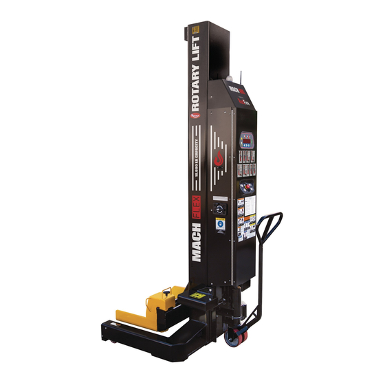
Column Lift Systems
24V DC Powered
MCHF14/ MCHM14 14,000 lbs. per column
MCHF19/ MCHM19 18,800 lbs. per column
MCHF20/ MCHM20 20,000 lbs. per column
MCH20
Reference ANSI/ALI ALIS,
Safety Requirements for
LP20680
CO10965.2
MCH19
IN20789
Rev. D 8.6.19
I
I
N
N
S
S
T
T
A
A
L
L
L
L
A
A
T
T
I
I
O
O
N
N
-
-
S
S
A
A
F
F
E
E
T
T
Y
Y
-
-
O
O
P
P
E
E
R
R
A
A
T
T
I
I
O
O
N
N
-
-
M
M
A
A
I
I
N
N
T
T
E
E
N
N
A
A
N
N
C
C
E
E
Advertisement

Related Manuals for Rotary MCH14 Series


Summary of Contents for Rotary MCH14 Series
- Page 1 MCHF14/MCHM14 Series MCHF19/MCHM19 Series MCHF20/MCHM20 Rail Series Column Lift Systems 24V DC Powered MCHF14/ MCHM14 14,000 lbs. per column MCHF19/ MCHM19 18,800 lbs. per column MCHF20/ MCHM20 20,000 lbs. per column MCH14 MCH20 MCH19 Reference ANSI/ALI ALIS, IMPORTANT Safety Requirements for Installation and Service of Automotive Lifts before installing lift.
-
Page 2: Table Of Contents
5. If model ordered which includes batteries, if column includes lockable disconnect, remove wire tie securing lift 1. Unloading: Rotary’s Mobile Lift System units are shipped in off position, if column does not have lockable disconnect in the vertical position. - Page 3 Control Box And Power Unit Cover Removed For Clarity Fig. 1 Power Unit Tank Battery Locations M20 Bolt M10 Socket Head Adjust For Ground Adjust For Ground Clearance Clearance (if equipped) Ensure vehicle tires are properly inflated before lifting. DO NOT use on asphalt. Lift must be WARNING DO NOT exceed tire load rating when raising vehicle.
- Page 4 6. Install Antenna: Remove antenna from packaged location (taped to control box) and install as shown, Fig. 2. Antenna Fig. 2 7. Confirm battery charger is turned ON. 10. Charging dock to be powered by 100-240V AC 50/60hz. Dock can be set on workstation or mounted 8.
- Page 5 12. Bleed mobile columns, Fig. 2b. Fully raise lift, then lower to just below lowest lock. Loosen bleed screw to release air from system. Close screw and repeat steps a and b until there is no air in the system and fluid runs clear. Bleed Screw Fig.
-
Page 6: Safety Instructions
Use only qualified until the power has been shut off to the lift. lift service personnel and genuine Rotary parts to make repairs. • Do Not operate equipment with a damaged cord or if the equipment has been dropped or damaged. - Page 7 The Owner/Employer: • Shall ensure that lift operators are qualified and that they are trained in the safe use and operation of the lift using the manufacturer’s operating instructions; ALI/SM 93-1, ALI Lifting it Right safety manual; ALI/ST-90 ALI Safety Tips card; ANSI/ALI ALOIM-2008, American National Standard for Automotive Lifts-Safety Requirements for Operation, Inspection and Maintenance;...
- Page 9 Remote Controller Panel Diagram Lift Initialization Instructions: E-STOP Control Panel Diagram HEIGHT WEIGHT SINGLE / PAIR / ALL (FLEX MAX ONLY) POWER ACCESSORY 6X COLUMN LIGHT ON/OFF S___3 BUTTONS FIND Fig. 5 COLUMN LED REMOTE INDICATORS Fig. 4 ACCESSORY RESUME LIGHT ON/OFF MENU MENU...
- Page 10 Lift Operation: Do Not go under vehicle unless all tires are in secure Before attempting to lift any vehicle, be WARNING contact with forks. Lower lift and repeat vehicle and/or lift sure that: spotting and loading procedure if required. a.) Vehicle individual axle weight does not exceed two lift c.) Press the Lower To Locks Button to lower columns onto columns combined capacity.
- Page 11 Operating Instruction Details/Options 1. Press Protect: 4. Column LED Indication – Summary of column LED’s, Remote controller goes to inactive state if no button is refer to Fig. 5: pressed after 10 seconds. When in this state pressing up and down will cause no movement. Remote Green Light –...
- Page 12 The accessory kits are FA8136 (w/o membrane), and FA8137 (with membrane). If Flex Max authentication board is not found by columns controls on all columns in the system, the system will revert to functioning as standard Flex. Fig. 6 Fig. 7 ROTARY LIFT EXPRESS Power Up Switch...
- Page 13 Fore And Aft Kit Required Fig. 8 Fore And Aft Example: Remote Display For Kit Required 2-Post Flex Mobile Columns Fore And Aft Kit Required Example: Remote Display For 8-Post Flex Mobile Columns...
- Page 14 Emergency Stop Process Mobile Column wired or wireless Emergency Stop process. 3. If the Emergency Stop Switch does not affect the operation of the system or post, immediately go to the 1. Always follow safe lifting practices detailed in the Main DC Disconnect Switch of the unresponsive unit and instruction manual according to ANSI and ALI.
-
Page 15: Emergency Lowering
Emergency (no power) Lowering: • During lowering of lifts, ensure that vehicle does not move into an inclined position. • Lower columns equally. • Remove tool trays, safety stands, etc. from area. NOTE: Top cover not shown for clarity. • Remain clear of forks and vehicle when lowering. -
Page 16: Battery Charging
Battery Charging 1. Battery chargers can be plugged in nearly continuously or as needed. Life of the battery can be decreased if the batteries are charged regularly (for example, after every use), and not allowed to be fully discharged. If lift will remain plugged in AGM batteries are recommended. -
Page 17: Satety Information
Safety Information Do not disassemble the charger. Incorrect reassembly may result in a risk of electric shock or fire. IMPORTANT SAFETY INSTRUCTIONS To reduce the risk of electric shock, unplug the charger KEEP THESE INSTRUCTIONS! from outlet before attempting any maintenance or cleaning. Disconnecting the leads will not reduce this risk. -
Page 18: Maintenance Instructions
Maintenance Instructions • Monthly: Examine Cords: Check the condition of the If you are not completely familiar with WARNING charging cords on each column. Replace worn or automotive lift maintenance procedures Stop: contact broken cords as required. factory for instructions. •... - Page 19 The column will drop out of the service menu after 10 seconds of inactivity. A limited service menu can be accessed with the Rotary Tool. If software revision 8 or later is installed, scroll through the columns display using the up and down menu keys until the service menu option becomes available.
-
Page 20: Trouble Shooting
TROUBLE SHOOTING Code Description Troubleshooting steps CPU error The processor has detected an error. Press to clear. If the problem continues, call for service. Improper configuration The column has not been assigned a position, and is connected to a locked system. Press to clear. - Page 21 TROUBLE SHOOTING (CONTINUED) Code Description Troubleshooting steps Low Battery Error Batteries reached critical level. Check battery charge. Weight Sensor Error An error has occurred with the weight sensing device. Weight values displayed are inaccurate until next lift power cycle. Wireless Radio Error An error has occurred when attempting to communicate to the column's wireless radio.
-
Page 22: Lift Lockout/Tagout Procedure
The responsibility for assuring that this procedure is followed is binding upon all employees and service personnel from outside service companies (i.e., Authorized Rotary Installers, contactors, etc.). All employees shall be instructed in the safety significance of the lockout procedure by the facility owner/manager. Each new or transferred employee along with visiting outside service personnel shall be instructed by the owner/manager (or assigned designee) in the purpose and use of the lockout procedure. - Page 24 Please return this booklet to literature package, and give to lift owner/operator. Thank You Trained Operators and Regular Maintenance Ensures Satisfactory Performance of Your Rotary Lift. Contact Your Nearest Authorized Rotary Parts Distributor for Genuine Rotary Replacement Parts. See Literature Package for Parts Breakdown.
Need help?
Do you have a question about the MCH14 Series and is the answer not in the manual?
Questions and answers