Table of Contents
Advertisement
Advertisement
Table of Contents

Related Manuals for Pilz PNOZ s4.1


Summary of Contents for Pilz PNOZ s4.1
- Page 1 PNOZ s4.1 Safety relays Operating Manual 21890-EN-07...
- Page 2 Preface This document is a translation of the original document. All rights to this documentation are reserved by Pilz GmbH & Co. KG. Copies may be made for internal purposes. Suggestions and comments for improving this documentation will be gratefully received.
-
Page 3: Table Of Contents
Function description Timing diagram Installation Wiring Preparing for operation Operating modes Set operating modes Connection Operation Status indicators Error indicators Faults - malfunctions Dimensions in mm Technical details Safety characteristic data Supplementary data Service life graph Operating Manual PNOZ s4.1 21890-EN-07... - Page 4 Contents Remove plug-in terminals Order reference EC declaration of conformity Operating Manual PNOZ s4.1 21890-EN-07...
-
Page 5: Introduction
PNOZ s4.1 Introduction Validity of documentation This documentation is valid for the product PNOZ s4.1. It is valid until new documentation is published. This operating manual explains the function and operation, describes the installation and provides guidelines on how to connect the product. -
Page 6: Safety
In order to achieve the re- quired safety level for the overall plant/machine, define the safety requirements for the plant/machine and then define how these must be implemented from a technical and organ- isational standpoint. Operating Manual PNOZ s4.1 21890-EN-07... -
Page 7: Use Of Qualified Personnel
Note for overvoltage category III: If voltages higher than low voltage (>50 VAC or >120 VDC) are present on the unit, connected control elements and sensors must have a rated insulation voltage of at least 250 V. Operating Manual PNOZ s4.1 21890-EN-07... -
Page 8: Unit Features
The circuit is redundant with built-in self-monitoring. The safety function remains effective in the case of a component failure. The correct opening and closing of the safety function relays is tested automatically in each on-off cycle. Operating Manual PNOZ s4.1 21890-EN-07... -
Page 9: Block Diagram/Terminal Configuration
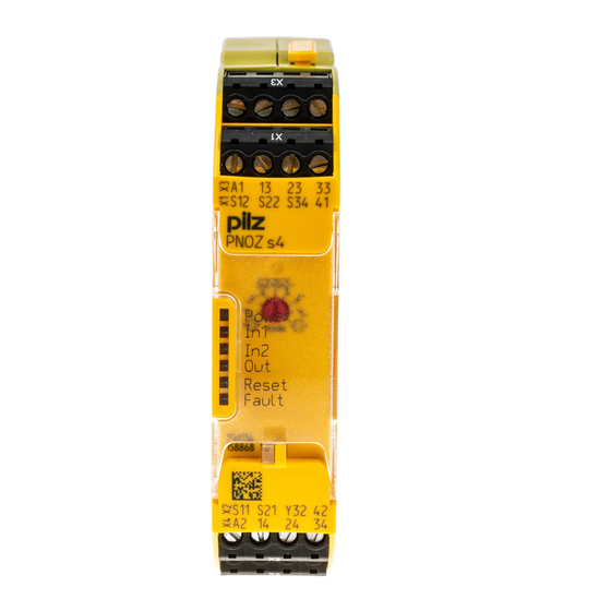
: 48 - 240 VAC/DC; Order no. 750154, 751154 Fig.: Centre: Front view with cover, right: Front view without cover *Insulation between the non-marked area and the relay contacts: Basic insulation (over- voltage category III), Protective separation (overvoltage category II) Operating Manual PNOZ s4.1 21890-EN-07... -
Page 10: Function Description
Single-channel operation: no redundancy in the input circuit, earth faults in the start circuit and input circuit are detected. Dual-channel operation without detection of shorts across contacts: Redundant input circuit, detects PNOZ s4.1 – earth faults in the start and input circuit, –... -
Page 11: Timing Diagram
The safety relay should be installed in a control cabinet with a protection type of at least IP54. Use the notch on the rear of the unit to attach it to a DIN rail (35 mm). Operating Manual PNOZ s4.1 21890-EN-07... -
Page 12: Wiring
If you connect contact expansion modules to a base unit with a universal power supply, you will need to limit the conventional thermal current at the contact expansion modules' safety contacts to 70 % of the stated current (see technical details for contact expansion module). Operating Manual PNOZ s4.1 21890-EN-07... -
Page 13: Preparing For Operation
With detection of In2+ In2- In2+ In2- In2+ In2- In2+ In2- shorts across contacts Connection Supply voltage Unit types with Unit types with Supply voltage 48 - 240 VAC/DC 24 VDC Operating Manual PNOZ s4.1 21890-EN-07... - Page 14 – The operating mode selector switch must be set to "Without detection of shorts across contacts", as shorts across contacts are detected by the ESPE. Operating Manual PNOZ s4.1 21890-EN-07...
- Page 15 If a base unit and a contact expansion module from the PNOZsigma range are connected via the connector, no additional wiring is necessary. Legend S1/S2: E-STOP/safety gate switch S3: Reset button : Switch operated : Gate open Operating Manual PNOZ s4.1 21890-EN-07...
-
Page 16: Operation
Supply voltage is present. Input circuit at S12 is closed. Input circuit at S22 is closed. Safety contacts are closed and semiconductor output Y32 carries a high signal. RESET 24 VDC is present at S34. Operating Manual PNOZ s4.1 21890-EN-07... -
Page 17: Error Indicators
Remedy: Open both input circuits, S12 and S22, simultaneously and then close again. FAULT Diagnostics: Power-up blocked due to short-term interruption at S22; input cir- cuits not operated simultaneously Remedy: Open both input circuits, S12 and S22, simultaneously and then close again. Operating Manual PNOZ s4.1 21890-EN-07... -
Page 18: Faults - Malfunctions
Remedy: Switch off the supply voltage and set the required operating mode on operating mode selector switch "mode". Faults - malfunctions Contact malfunctions: If the contacts have welded, reactivation will not be possible after the input circuit has opened. Dimensions in mm *with spring-loaded terminals Operating Manual PNOZ s4.1 21890-EN-07... -
Page 19: Technical Details
24 V Current at 50 mA 50 mA 50 mA 50 mA Input circuit DC Start circuit DC 50 mA 50 mA 50 mA 50 mA Feedback loop 50 mA 50 mA 50 mA 50 mA Operating Manual PNOZ s4.1 21890-EN-07... - Page 20 30 Ohm 30 Ohm Dual-channel with detection of shorts across contacts at UB 30 Ohm 30 Ohm – – Semiconductor 750124 750154 751124 751154 outputs Number Voltage 24 V 24 V 24 V 24 V Operating Manual PNOZ s4.1 21890-EN-07...
- Page 21 0,01 A 0,01 A 0,01 A Min. current Max. current 150 W 150 W 150 W 150 W Max. power Utilisation category In accordance with the standard EN 60947-5-1 EN 60947-5-1 EN 60947-5-1 EN 60947-5-1 Operating Manual PNOZ s4.1 21890-EN-07...
- Page 22 EN 60947-5-1 EN 60947-5-1 EN 60947-5-1 Max. melting in- 66 A²s 66 A²s 66 A²s 66 A²s tegral Blow-out fuse, quick Blow-out fuse, slow Blow-out fuse, gG 6 A Circuit breaker 24V AC/DC, char- acteristic B/C Operating Manual PNOZ s4.1 21890-EN-07...
- Page 23 4 V Conv. therm. cur- rent with 1 con- tact – – Conv. therm. cur- rent with 2 con- tacts – – Conv. therm. cur- rent with 3 con- tacts 4,5 A 4,5 A – – Operating Manual PNOZ s4.1 21890-EN-07...
- Page 24 50 ms 50 ms 50 ms With monitored start with falling 55 ms 55 ms 55 ms 55 ms edge typ. With monitored start with falling edge max. 70 ms 70 ms 70 ms 70 ms Operating Manual PNOZ s4.1 21890-EN-07...
- Page 25 93 % r. h. at 40 °C 93 % r. h. at 40 °C 93 % r. h. at 40 °C 93 % r. h. at 40 °C Condensation during operation Not permitted Not permitted Not permitted Not permitted Operating Manual PNOZ s4.1 21890-EN-07...
- Page 26 751124 751154 Mounting position Mechanical life 10,000,000 cycles 10,000,000 cycles 10,000,000 cycles 10,000,000 cycles Material Bottom Front Connection type Spring-loaded ter- Spring-loaded ter- Screw terminal Screw terminal minal minal Mounting type plug-in plug-in plug-in plug-in Operating Manual PNOZ s4.1 21890-EN-07...
- Page 27 22,5 mm 22,5 mm 22,5 mm 22,5 mm Depth 120 mm 120 mm 120 mm 120 mm Weight 190 g 210 g 190 g 210 g Where standards are undated, the 2014-07 latest editions shall apply. Operating Manual PNOZ s4.1 21890-EN-07...
-
Page 28: Safety Characteristic Data
If the service life graphs are not accessible, the stated PFH value can be used irrespective of the switching frequency and the load, as the PFH value already considers the relay's B10d value as well as the failure rates of the other components. Operating Manual PNOZ s4.1 21890-EN-07... -
Page 29: Service Life Graph
The wear is mainly caused by the electrical load; the mechanical load is negli- gible. Switching current (A) Fig.: Service life graphs at 24 V DC and 230 V AC Switching current (A) Fig.: Service life graphs at 110 V DC Operating Manual PNOZ s4.1 21890-EN-07... - Page 30 Screw terminals 750 124 PNOZ s4.1 C 24 VDC Spring-loaded terminal 751 124 PNOZ s4.1 48 - 240 V AC/DC Screw terminals 750 154 PNOZ s4.1 C 48 - 240 V AC/DC Spring-loaded terminals 751 154 Operating Manual PNOZ s4.1 21890-EN-07...
- Page 31 European Parliament and of the Council. The complete EC Declaration of Conformity is available on the Internet at www.pilz.com/downloads. Representative: Norbert Fröhlich, Pilz GmbH & Co. KG, Felix-Wankel-Str. 2, 73760 Ost- fildern, Germany Operating Manual PNOZ s4.1...
- Page 32 Back cover Support Technical support is available from Pilz round the clock. Americas Australia Scandinavia Brazil +61 3 95446300 +45 74436332 +55 11 97569-2804 Spain Canada Europe +34 938497433 +1 888-315-PILZ (315-7459) Austria Switzerland +41 62 88979-30 Mexico +43 1 7986263-0...
Need help?
Do you have a question about the PNOZ s4.1 and is the answer not in the manual?
Questions and answers