Pilz PNOZ s9 Operating Manual
Hide thumbs
Also See for PNOZ s9:
- Operating instructions manual (20 pages) ,
- Operating instructions manual (21 pages)
Table of Contents
Advertisement
Advertisement
Table of Contents

Related Manuals for Pilz PNOZ s9


Summary of Contents for Pilz PNOZ s9
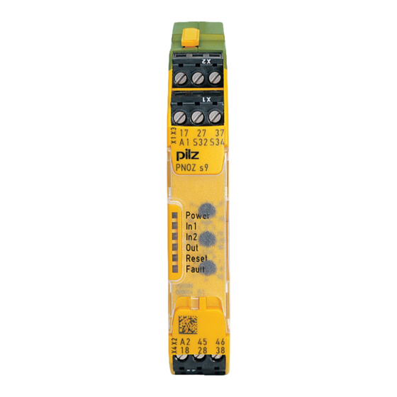
- Page 1 PNOZ s9 Safety relays Operating Manual-21401-EN-10...
- Page 2 Preface This document is the original document. All rights to this documentation are reserved by Pilz GmbH & Co. KG. Copies may be made for the user's internal purposes. Suggestions and comments for improving this documenta- tion will be gratefully received.
-
Page 3: Table Of Contents
Delay-on energisation Installation Wiring Preparing for operation Operating modes and delay time Set operating modes Set delay time Connection Operation Status indicators Fault indicators Faults - malfunctions Dimensions in mm Technical details Safety characteristic data Operating Manual PNOZ s9 21401-EN-10... - Page 4 Contents Supplementary data Service life graph Permitted operating height Remove plug-in terminals Order reference EC declaration of conformity Operating Manual PNOZ s9 21401-EN-10...
-
Page 5: Introduction
PNOZ s9 Introduction Validity of documentation This documentation is valid for the product PNOZ s9. It is valid until new documentation is published. This operating manual explains the function and operation, describes the installation and provides guidelines on how to connect the product. -
Page 6: Safety
The following is deemed improper use in particular Any component, technical or electrical modification to the product, Use of the product outside the areas described in this manual, Use of the product outside the technical details (see Technical details [ 20]). Operating Manual PNOZ s9 21401-EN-10... -
Page 7: Safety Regulations
Damage can be attributed to not having followed the guidelines in the manual, Operating personnel are not suitably qualified, Any type of modification has been made (e.g. exchanging components on the PCB boards, soldering work etc.). Operating Manual PNOZ s9 21401-EN-10... -
Page 8: Disposal
The safety function remains effective in the case of a component failure. Earth fault in the feedback loop is detected. Earth fault in the input circuit: The output relays de-energise and the safety contacts open. Operating Manual PNOZ s9 21401-EN-10... -
Page 9: Block Diagram/Terminal Configuration
If the input circuit is opened for more than 10 ms, the safety contacts will open immedi- ately and the auxiliary contact will be closed. Operating Manual PNOZ s9 21401-EN-10... -
Page 10: Timing Diagrams
[2]: No retriggering in the time t NOTICE At the latest the safety contacts open after the set delay time + 20 ms + 15% of the set value, even in the case of a component failure. Operating Manual PNOZ s9 21401-EN-10... -
Page 11: Delay-On De-Energisation, Retriggerable
NOTICE At the latest the safety contacts open after the set delay time + 20 ms + 15% of the set value, even in the case of a component failure. Operating Manual PNOZ s9 21401-EN-10... -
Page 12: Pulse On Switching On
[4]: Normal operating cycle with supply interruption < 10 ms NOTICE At the latest the safety contacts open after the set delay time + 20 ms + 15% of the set value, even in the case of a component failure. Operating Manual PNOZ s9 21401-EN-10... -
Page 13: Delay-On Energisation
The safety relay should be installed in a control cabinet with a protection type of at least IP54. Use the notch on the rear of the unit to attach it to a DIN rail (35 mm). Operating Manual PNOZ s9 21401-EN-10... -
Page 14: Wiring
Do not adjust the rotary switch during operation, otherwise an error mes- sage will appear, the safety contacts will open and the unit will not be ready for operation until the supply voltage has been switched off and then on again. Operating Manual PNOZ s9 21401-EN-10... -
Page 15: Set Operating Modes
= 4 s, n = 5 Delay time = 5 x 4 = 20 s Connection Supply voltage Supply voltage INFORMATION The supply voltage may only be connected as shown in the examples listed below! Operating Manual PNOZ s9 21401-EN-10... - Page 16 The inputs that evaluate the feedback loop will depend on the base unit and application. * with PNOZelog as base unit: The selectable delay-on de-energisation of PNOZ s9 may only be used with the safety relay PNOZ e1p. Other PNOZelog safety relays must be oper- ated without delay-on de-energisation.
-
Page 17: Operation
The safety functions may only be checked by qualified personnel. The unit is ready for operation when the Power LED is permanently lit. LEDs indicate the status and errors during operation: LED on LED flashes Operating Manual PNOZ s9 21401-EN-10... -
Page 18: Status Indicators
Remedy: Insert plug terminator, switch supply voltage off and then on again. With base unit PNOZsigma: Diagnostics: Input circuit S32 is closed without authorisation FAULT Diagnostics: Internal error, unit defective Remedy: Switch supply voltage off and then on again, change unit if neces- sary. Operating Manual PNOZ s9 21401-EN-10... -
Page 19: Faults - Malfunctions
In the case of an error, the delay-on de-energisation contacts may open before the delay time has elapsed. Dimensions in mm *with spring-loaded terminals 98 (3.86") 17,5 (0.69") * 100 (3,94") Operating Manual PNOZ s9 21401-EN-10... -
Page 20: Technical Details
Current pulse, feed- back loop 0,1 A 0,1 A 0,1 A Pulse duration, feed- 20 µs 20 µs 20 µs back loop Max. overall cable resist- ance Rlmax Single-channel at UB 30 Ohm 30 Ohm 30 Ohm Operating Manual PNOZ s9 21401-EN-10... - Page 21 DC13 (6 cycles/min) at 24 V 24 V 24 V Max. current Utilisation category of auxiliary contacts AC15 at 230 V 230 V 230 V Max. current DC13 (6 cycles/min) at 24 V 24 V 24 V Max. current Operating Manual PNOZ s9 21401-EN-10...
- Page 22 Delay-on de-energisation 40 ms 40 ms 40 ms With E-STOP typ. With E-STOP max. 50 ms 50 ms 50 ms Recovery time at max. switching frequency 1/s After power failure 800 ms 800 ms 800 ms Operating Manual PNOZ s9 21401-EN-10...
- Page 23 10 - 55 Hz Amplitude 0,35 mm 0,35 mm 0,35 mm Airgap creepage In accordance with the standard EN 60947-1 EN 60947-1 EN 60947-1 Overvoltage category Pollution degree 250 V 250 V 250 V Rated insulation voltage Operating Manual PNOZ s9 21401-EN-10...
- Page 24 100 mm 100 mm Width 17,5 mm 17,5 mm 17,5 mm Depth 120 mm 120 mm 120 mm Weight 175 g 175 g 175 g Where standards are undated, the 2017-01 latest editions shall apply. Operating Manual PNOZ s9 21401-EN-10...
-
Page 25: Safety Characteristic Data
A safety function's SIL/PL values are not identical to the SIL/PL values of the units that are used and may be different. We recommend that you use the PAScal software tool to calculate the safety function's SIL/PL values. Operating Manual PNOZ s9 21401-EN-10... -
Page 26: Supplementary Data
The service life graphs indicate the number of cycles from which failures due to wear must be expected. The wear is mainly caused by the electrical load; the mechanical load is negli- gible. Switching current (A) Fig.: Service life graphs at 24 V DC and 230 V AC Operating Manual PNOZ s9 21401-EN-10... - Page 27 To increase the service life, sufficient spark suppression must be provided on all output contacts. With capacitive loads, any power surges that occur must be noted. With DC con- tactors, use flywheel diodes for spark suppression. Operating Manual PNOZ s9 21401-EN-10...
-
Page 28: Permitted Operating Height
From an operating height of 2000 m the max. permitted ambient temperature is re- duced by 0.5 °C/100 m Operating height Permitted ambient temperature 3000 m 50 °C 4000 m 45 °C 5000 m 40 °C Operating Manual PNOZ s9 21401-EN-10... -
Page 29: Remove Plug-In Terminals
European Parliament and of the Council. The complete EC Declaration of Conformity is available on the Internet at www.pilz.com/downloads. Representative: Norbert Fröhlich, Pilz GmbH & Co. KG, Felix-Wankel-Str. 2, 73760 Ost- fildern, Germany Operating Manual PNOZ s9... - Page 30 Back cover Support Technical support is available from Pilz round the clock. Americas Australia Scandinavia +45 74436332 Brazil +61 3 95600621 +55 11 97569-2804 Spain Canada Europe +34 938497433 +1 888-315-PILZ (315-7459) Austria Switzerland Mexico +43 1 7986263-0 +41 62 88979-30...
Need help?
Do you have a question about the PNOZ s9 and is the answer not in the manual?
Questions and answers