
Related Manuals for Daikin LX10F11B3


Summary of Contents for Daikin LX10F11B3
- Page 1 DAIKIN INVERTER CONTAINER REFRIGERATION UNIT Service Manual LX10F11B3 or later (DECOS Va) TR 16-02...
- Page 2 Make sure to read these instructions before operation. This manual provides the minimum information required to operate the container refrigeration unit LX10F series or later including the part names of each operating section, how to turn the power on and how to change the temperature setting, as well as the functions of the product and maintenance work, etc.
-
Page 3: Table Of Contents
Contents Chapter 3 PTI & Periodic Inspection …………… 3-1 SAFETY PRECAUTIONS DANGER ………………………………………………4 3.1 Pre-Trip Inspection …………………………… 3-2 WARNING ………………………………………………4 3.2 Manual Inspection ……………………………… 3-3 CAUTION ………………………………………………4 3.3 Automatic PTI ………………………………… 3-5 3.3.1 Automatic PTI Step No. and Contents … 3-6 Chapter 1 Unit Specifications ……………………... - Page 4 4.10 External Receptacle Wiring Diagrams …… 4-27 4.10.1 Power Plug (P1) ……………………… 4-27 4.10.2 PC Port Receptacle (PPR1, 2) ……… 4-27 4.10.3 Remote Monitoring Receptacle (RM; option) …………………………… 4-27 4.10.4 USDA Sensor 1 to 3 Receptacles (USDA 1 to 3; options) ……………… 4-27 Cargo Temperature Sensor Receptacle (CTR;...
-
Page 5: Safety Precautions
Securely close the control box cover. Otherwise, it will allow water entry. R134a should be used as refrigerant. Use only Daikin specified refrigerant oil (IDEMITSU, Daphne Hermetic Oil FVC68D). Be sure to prevent air from becoming mixed in with refrigerant, and never charge the equipment used for Open the oil bottle, just before charging the oil. - Page 6 This product contains greenhouse gases covered by Kyoto Protocol. Do not discharge refrigerant into atmosphere. Refrigerant type : R134a GWP (1) value : 1430 (1) GWP=global warming potential You may be required to perform periodic refrigerant leakage inspections. Contact Daikin for details.
- Page 7 https://daikin-p.ru...
-
Page 8: Chapter 1 Unit Specifications
Chapter 1 Unit Specifications 1.1 Operation Range and Main Specifications 1.1.1 Operation Range 1.1.2 Main Specifications 1.2 Protection Device and Setting Value 1.3 Construction 1.3.1 Outside View 1.3.2 Inside View 1.3.3 Control Box 1.3.4 CPU Board and I/O Board 1.3.5 Inverter Box... -
Page 9: Operation Range And Main Specifications
1.1 Operation Range and Main Specifications 1.1.1 Operation Range Item Operation Range Ambient temperature range +50℃〜-30℃ (+122℉〜-22℉) Inside temperature range +30℃〜-30℃ (+86℉〜-22℉) 50Hz:380 / 400 / 415V Voltage 60Hz:440 / 460V Voltage fluctuation rate±10% Vibration/impact Horizontal direction: 5G, vertical direction: 2G 1.1.2 Main Specifications... -
Page 10: Protection Device And Setting Value
1.2 Protection Device and Setting Value Component Name Detector Symbol Setting Value Alarm OFF≧2400kPa(24.47kg/cm E101 ) High pressure switch ON≦1900kPa(19.37kg/cm F101 ) Pressure relief valve Open≧2450kPa(25.0kg/cm ) − Fusible plug 95〜100℃(203〜212℉) − − Built-in thermal protector OFF≧135℃±5℃(275℉±41℉) − for condenser fan motor ON≦86℃±15℃(187℉±59℉)... -
Page 11: Construction
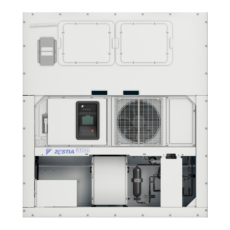
1.3 Construction 1.3.1 Outside View Valve chamber Display panel Access Condenser HSV RSV DMV Economizer Ventilator & key pad panel ECO OUT Dryer ECO IN ③ Compressor chamber AMBS Inverter box Compressor ① cover Model name plate Storage space for power cable... -
Page 12: Inside View
1.3.2 Inside View 〈TOP OF VIEW〉 RS, DRS (Option) Reheat coil Evaporator (Option) HuS (Option) Evaporator (Option) USDA1 USDA2 USDA3 RPP2 SS, DSS 【Sensor】 【Interface】 : Return Air Temperature Sensor for Data : Cargo Temperature Sensor Receptacle Recorder (Option) (Option) :... -
Page 13: Control Box
1.3.3 Control Box EFH EFL CFH CFL CPU board (EC1) I/O board (EC2) PCC2 PCC1 PT/CT (EC7) Earth RCD (option) (Behind of CB) terminal block installation position Operation Panel Operation board :Wake-up Battery (Rechargeable Battery) (EC3) :Circuit Breaker (ELCB) :Magnetic Contactor, CFM high speed... -
Page 14: Cpu Board And I/O Board
1.3.4 CPU Board and I/O Board USB memory port LED lamp CPU board(EC1) I/O board(EC2) Spare PCC1 PCC2 F10A/250V F10A/250V MODEM PT/CT F10A/250V option AMBS ECO IN MODEM DCHS1 ECO OUT USDA1 DCHS2 USDA2 USDA3 option PCC1 BATTERY PCC2... -
Page 15: Inverter Box
1.3.5 Inverter Box AC reactor Noise filter board (EC9) Inverter board (EC8) Noise filter board(EC9) Inverter board(EC8) X801A L1B-2 X91A Note: Wiring diagram for the unit including inverter circuit is put on back side of the control box cover. -
Page 16: Valves And Functions
1.3.6 Valves and Functions HSV: Hot gas Solenoid Valve HSV is opened while in defrost and heating EEV: Electronic Expansion Valve operation to supply hot-gas from the EEV controls super heat at the evaporator outlet compressor to the evaporator and drain pan. -
Page 17: Printed Circuit Board
2.3) to CPU board. The judgment for operation continuing and stopping is conducted by CPU board. Use Daikin spare parts for CPU board replacement. Output from inverter is made of frequent switching After replacement, configuration items are control by power module and results to creating transmitted from operation board. -
Page 18: Operation Mode And Control
1.4 Operation Mode and Control to Cooling OFF. Compressor stops and EFM continues to run at low speed. If temperature rises 1.4.1 Frozen Mode to ≧SP+0.5℃ , the unit will return to the modulated cooling. ●Set Point and Control Temperature Sensor Unit operates in frozen mode between Set Point ●Condenser Fan Motor, CFM... -
Page 19: Chilled Mode
1.4.2 Chilled Mode The operation is same as defrost mode except EFM runs with high speed. ●Set Point and Control Temperature Sensor Unit operates in chilled mode between Set Point ●Evaporator Fan Motor, EFM +30.0℃ 〜 -9.9℃ controlled by the supply air EFM runs at High or Low speed in Modulation as temperature sensor (SS). -
Page 20: Dehumidification Mode (Option)
1.4.3 Dehumidification Mode (Option) ●Dehumidification Operation Dehumidification operation starts when the Dehumidification operation reduces the internal following conditions are met during modulated relative humidity using the reheat coil that heats up cooling in the chilled mode. the air cooled by the evaporator. -
Page 21: Defrost Mode
1.4.4 Defrost Mode ●Defrost Initiation ●Hot-Gas Defrost System Short timer A hot gas system is adopted for the heat source; (12Hr when RS<-15℃) I.e. the high temperature and high pressure Pull-down When supply air temperature does not Automatic refrigerant discharged from the compressor is drop 0.2℃... -
Page 22: Compressor, Fan Motor, Valve Function
1.4.5 Compressor, Fan Motor, Valve Function ●Frozen Mode Cooling ------ Notes ----- Component Name Full Cool Modulation ※1 EFM operates at RS≦-5.0℃ Compressor CM※7,8 Max.130 rps 20〜130 rps ※ 2 High pressure Motor Evaporator fan motor H(L ※1) control Condenser fan motor H/L/OFF ※2 H/L/OFF ※2... -
Page 23: Common Control
1.4.6 Common Control difference between RS (or SS) and SP. (at the speed of as low as 20 rps) ●Compressor running control The compressor stops at small heat load condition. Compressor changes speed Min. 20 rps to Max. 130 rps with inverter control. -
Page 24: Optional Functions
●Pump down control ●Precautions when setting ASC operation Pump down with EEV closed before defrosting Access to ※2-5 ASC settings for ASC operation in initiation, before heating operation, or during paragraph 2.3. the start-up control of the compressor. Collect refrigerant into the receiver, and terminate the ●Display... -
Page 25: Cold Treatment Transport
1.5.2 Cold Treatment Transport ●USDA report Temperature record data during cold treatment Units equipped with USDA receptacle can perform transport can be prepared in the format in cold treatment transport in conformity with USDA. conformity with USDA standards which is... -
Page 26: Act, Automatic Cold Treatment
1.5.3 ACT, Automatic Cold Treatment ●Indications during ACT operation During USDA operation, ACT is displayed in the ●ACT operation SET-MODE area. When cold treatment is completed during USDA The SET-MODE area will change to USDA INFO transport (when the standard period has passed... -
Page 27: Ventilator Volume Detection (Fa Sensor)
1.5.4 Ventilator Volume Detection 1.5.5 Remote Monitoring Receptacle (FA Sensor) Able to install receptacle for remote monitoring on front of the unit. Sometimes FA (Fresh Air) is taken in with the In case of connect remote monitoring cable, below ventilator opened in the chilled mode. -
Page 28: Battery Mode
1.6 Battery Mode When the unit is not connected to the power source, following work can be done with battery mode function. If the wake-up battery is not sufficiently charged, the function may not operate. ●Setting functions Unit ON/OFF... -
Page 29: Information Interchange With Personal Computer
1.7 Information Interchange with Personal Computer The electronic controller has an internal memory function to record the set point temperature, refrigeration temperature, operation mode, alarm and the report of automatic PTI during transportation in addition to the normal operation control. -
Page 30: Chapter 2 Controller
Chapter 2 Controller 2.1 Operation Panel 2.2 Controller Functions List 2.3 Operation Procedure 2.4 Wake-up Battery (Rechargeable Battery) 2.5 Alarm Code 2.6 Alarm Diagnosis 2.7 General Diagnosis... -
Page 31: Operation Panel
2.1 Operation Panel IN RANGE LED LED light DEFROST LED ALARM LED Operation condition DEHUMID LED FULL COOL COOLING OFF MODULATION LCD panel FROZEN FULL COOL HEATING SET POINT SET-MODE HEATING OFF DEFROST -18.0 ℃ Set Point temperature DEHUMID... -
Page 32: Controller Functions List
2.2 Controller Functions List The controller installed in this unit has following functions. Access to the pertinent item in following pages for detail. Items Function Paragraph No. Temperature SP, Humidity SP, Bulb mode 2.3 ※1, 2-2, 2-3 Setting Defrost Interval AUTO or 3, 6, 9, 12 or 24Hr 2.3 ※2-1... -
Page 33: Operation Procedure
2.3 Operation Procedure Using the operation keys on the operation panel, the following settings and sensor information, etc. are displayed. ※1 Set Point temperature ※4 Configuration Information ※8 Manual Defrost ※12 Configuration Set Change ※5 Service Menu ※9 Current Alarm ※13 Optional Function Set... - Page 34 USDA 1 Temp ※12 Configuration Set USDA 2 Temp Battery Mode USDA 3 Temp Controller model Cargo Temp Log Interval Ventilation Volume Optional Sensor Battery Voltage Reheat Coil PTI History Ventilation (FA) --Y,M,D-- 1 Full USDA Sensor Type --Y,M,D--...
- Page 35 ※1 Set Point temperature Change 1. Press key to change Set Point temperature. Press key to determine. Set Temp. Range : -30.0℃ to +30.0℃ . ※2 Mode Set ※2-1 Defrost Interval Set ※2-2 Dehumidification Set Mode Set When Reheat Coil is set to "OFF" in ※12...
- Page 36 1. Dehumidification set 2. Humidity setpoint selection Dehumidification Set Humidity Setpoint Dehumidification Set 95 % RH Mode Set screen ▲▼:Change ▲▼:Change ▲▼:Change ENTER:Confirm ENTER:Confirm ENTER:Confirm Humidity Setpoint 75 % RH ▲▼:Change ENTER:Confirm ※2-3 Bulb Mode Set 1. Press key to select "ON" or "OFF" and press key to determine.
- Page 37 ※2-5 ASC, Automatic set point change (Option) Automatic Setpoint Change This function can change the set temperature automatically over time (for details, refer to paragraph 1.5.1). Step 1. Press key to select "ON" or "OFF". ▲▼:Change ENTER:Confirm ON : To enable automatic set point change OFF : To disable automatic set point change Step 2.
- Page 38 ※2-6 ACT, Automatic Cold Treatment Automatic Cold Treatment When cold treatment is completed during USDA transport, this ACT function switches the temperature to the preset ▲▼ : Change temperature automatically. (See paragraph 1.5.3 for the detail.) ENTER : Confirm Step 1.
- Page 39 ※3 Sensor Information The current values in each sensor in the unit are displayed. 1. Press key for page change. Press key to scroll. 2. Press the key for 1 second to return to the previous screen. (If you press the key for 3 seconds, the display will return to the operation screen.)
- Page 40 ※5 Service Menu ※5-1 Trip Chart Service Menu Trip Chart ※5-2 Trip Report Trip Report ※5-3 PTI History PTI Data ※5-4 Alarm Record Alarm Record Auto Pumpdown ※5-5 Automatic Pumpdown Monitoring log ※5-6 Monitoring Log (Start, Stop) ※5-1 Trip Chart Fig.
- Page 41 ※5-2 Trip Report Trip Report 1/131 The Trip report shows the trip data for up to 84 days Time SP(C) DSS(C) DRS(C) SHU(%) HU(%) 20 MAY,2009 (12 weeks) starting from the present. 21:00 –30.0 –30.3 –30.3 20:00 –30.0 –30.1 –30.3 The logging interval is the value that is selected in 19:00 –30.0 –30.1 –30.1...
- Page 42 ※6 Back Light Set (Adjustment of LCD screen brightness) Selection of Back Light function :Back light function available AUTO : Back light function available. (The back light is turned off in the absence of key operation for 5 minutes.) OFF :Back light off...
- Page 43 ※12 Configuration Set Caution !! 1. Optional function setting is done at factory. Normally, setting change at field is not necessary. 2. Ensure the circuit breaker is switched OFF after Configuration Set change. UNIT OFF Circuit Breaker OFF after setting change Preparation 10 sec.
- Page 44 ※12-10 Container I.D. Container I.D. Step 1. Press key to change the 1st letter. Step 2. Press key to move to the 2nd letter and press key to change 2nd letter. Step 3. Change the next letter and 7 numerals with same procedure.
- Page 45 A to Z. Step 1. Insert the USB memory that contains an authentication file. (※1) Download the authentication file from the Daikin's web site. Step 2. Press key to select "Data Download" in "USB Menu" and press key to determine.
- Page 46 ※14-2 Software Upload Battery Mode During upload Select software USB Menu Software Upload Battery Mode Software Upload Data Information Data Download INV-3031 Alarm Record Software Upload Uploading … INV-3032 Trip Record INV-3033 USB Menu ----- INV-3034 INV-3035 With power supply...
-
Page 47: Wake-Up Battery (Rechargeable Battery)
DC7.1V or less: The battery has deteriorated. Please send the battery replaced in EU The battery must be replaced. member nation to the following address. DAIKIN REFRIGERATION OFFICE Caution !! Fascinatio Boulevard 562, Cappele In case of using the battery for 2 years or more, USDA data logging etc., may not be executed... -
Page 48: Alarm Code
2.5 Alarm Code ●Alarm grouping F---:Alarm that unit stop E---:Alarm that unit restart or backup operation T---:Alarm during PTI (Refer to paragraph 3.3.2.) F5---:Alarm that unit stop related to inverter E5---:Alarm that unit restart related to inverter Communication Interrupted: Communication error between CPU board (EC1) and... - Page 49 ●E Alarm Alarm Diagnosis Alarm content Controller action code E101 HPS activates during operation Restart after 3 min. E105 Compressor operating current is too high (over DC 51A) Restart after 3 min. E106 Abnormal compressor operation Restart after 3 min.
- Page 50 ●Inverter F Alarm Alarm Diagnosis Alarm content Controller action code F528 E528 (Compressor does not startup) is generated 5 times. UNIT stops F52E E52E (Temporary compressor overcurrent ) is generated 4 times. UNIT stops F52F E52F (Compressor current sensor failure) is generated 4 times.
-
Page 51: Alarm Diagnosis
2.6 Alarm Diagnosis F101 ・ E101 Alarm F101 HPS activates within 30 seconds after compressor start. (OFF≧2400kPa, Generating ON≦1900kPa ) Logic E101 HPS activates during operation. (OFF≧2400kPa、ON≦1900kPa ) Possible *HPS or HPS circuit including connector X6 (inverter board) failure Causes *... - Page 52 F109 ・ E107 ・ E109 Alarm F109 LPT drops below -72 kPa within 2 seconds after compressor startup or E109 is generated Logic 9 times E109 LPT drops below -70 kPa for 2 seconds during operation. E107 DCHS1or DCHS2 becomes 135℃ or more for 10 minutes or 145℃ or more.
- Page 53 F301 ・ E303 ・ E305 ・ E307 ・ E311 Alarm ① After both CPU board (EC1) and operation board (EC3) are replaced together, the initial Logic setup is not executed. ② E307, E311--- After CPU board (EC1) is replaced, the configuration set is not executed.
- Page 54 F401 ・ F405 ・ F407 ・ F409 Alarm F401 SS, DSS, RS and DRS all failed during chilled mode, or X16A (CPU board) is disconnected. Logic F405 Multiple sensor (HPT,DCHS1,DCHS2) all failure. F407 Multiple sensor (HPT,LPT) all failure. Possible F409 Multiple sensor (LPT,DCHS1,DCHS2) all failure.
- Page 55 F703 Alarm The waveform of power supply is abnormal, therefore phase is not detected correctly. Logic Possible Abnormal waveform of power supply Causes Trouble Check power supply equipment or facility and provide power supply with correct phase wave Shooting...
- Page 56 F707 Alarm * Fuse F2U (I/O board) is open. Logic (E115 is also appeared when F707 is generated) Possible * Coil of magnet contactor or solenoid valve is burned-out. Causes Short circuited or grounded. *Ciruit line for below device is short circuit.
- Page 57 E115 Alarm *Condenser fan motor internal thermostat activated (OFF≧135℃±5℃ ) Logic (When F707(Fuse F2U is open) is generated, E115 is also appeared) Possible *Condenser fan motor lock Causes *Short circuit on the motor coil Trouble 1. Whether condenser fan motor generates heat? Shooting Whether motor shaft rotates smoothly by hand? Check whether it's locked.
- Page 58 E202 Alarm Automatic pumpdown failure Logic HPT≧2300kPa or DCHS1 or DCHS2≧120℃ during automatic pump-down. Possible Refrigerant overcharged Causes Trouble Recover refrigerant and charge with specified amount of refrigerant shown on unit name plate. Shooting Controller E202 Alarm display only Action...
- Page 59 E304 Alarm Incorrect configuration set (Reheat coil) Logic Possible Dehumidification operation is selected when reheat coil is set to "OFF" in Configuration Set. Causes Trouble Change the Reheat Coil setting from "OFF" to "ON" on the configuration setting Shooting (*12 Configuration Set in paragraph 2.3).
- Page 60 E405 ・ E439 (DCHS1) (DCHS2) Alarm ① DCHS1, 2≦-33℃ (687 kΩ) & 1 minute elapsed. Logic ② DCHS2≦AMBS & compressor speed is 53 rps or more ③ DCHS1, 2≧187℃ (1320 kΩ) & 3 minutes elapsed. Note 1: If the outside air temperature is -15℃ or lower, no judgment is made during startup control.
- Page 61 E406 ・ E407 ・ E409 (SGS) (EIS) (EOS) E411 ・ E435 ・ E437 (ECO IN) (ECO OUT) (AMBS) Alarm Above sensor≦-57℃ (100 kΩ) with 3 minute elapse Logic or ≧100℃ (0.221 kΩ) with 3 minute elapse Note: The alarm is activated when sensor or the circuit is disconnected (open) or short-circuited.
- Page 62 E413 ・ E415 (LPT) (HPT) Alarm 〈E413〉LPT: ≦-110 kPa with 3 minutes elapse or ≧1420 kPa with 3 minutes elapse Logic 〈E415〉HPT: ≦-340 kPa with 3 minutes elapse or ≧4260 kPa with 3 minutes elapse Possible 1. Faulty contact of connector X7A (CPU board) Causes 2.
- Page 63 E417 Alarm Power voltage sensor PT failure Logic Possible 1. Open circuit between connector X61A (PT/CT board)〜 X4A (CPU board) Causes 2. Fuse F11U is open (on PT/CT board) 3. Voltage sensor PT failure (on PT/CT board) Trouble Step 1. Check connector X61A (PT/CT board) and X4A (CPU board).
- Page 64 E425 ・ E427 (USDA1) (USDA2) E429 ・ E433 (USDA3) (CTS) Alarm When USDA sensor type "2" is set on ※12 Configuration set in paragraph 2.3 Logic ≦-39℃ (320kΩ) USDA sensor / CTS ≧96℃ (0.79kΩ) Note: The alarm is activated when sensor or the circuit is disconnected (open) or short-circuited.
- Page 65 E431 Alarm Humidity sensor (HuS) failure (Detect RH>120% or RH<20%) Logic Possible *Humidity sensor (HuS) deteriorated Causes *Contact failure of connector X20A (CPU board) *Controller failure Trouble Step 1. Replace the humidity sensor. Shooting Step 2. Check connector X20A (CPU board) and connector on the Humidity sensor cable located below fan deck.
- Page 66 E707 Alarm The power supply shut down temporarily during operation or the power supply phase waveform Logic was abnormal. Possible Power supply failure or abnormal power supply phase waveform Causes Trouble Check the power supply equipment and provide the correct power supply (power supply phase Shooting waveform).
- Page 67 E805 (FA sensor built in the unit only) Alarm FA sensor failure Logic Possible 1. Incorrect setting Causes 2. FA wiring is installed incorrectly. FA sensor failure 3. Controller (CPU board) failure Trouble 1-1. Check FA sensor setting. 1-1. Change setting as correct : ※12...
- Page 68 Communication Interrupted (E903) Alarm A communication error between CPU board and operation board Logic Possible 1. Open circuit between operation board (EC3) and CPU board (EC1) Causes 2. Operation board failure 3. CPU board failure Trouble Step 1. Check if the connector of cable between operation board (EC3) and CPU board (EC1) Shooting is inserted securely.
- Page 69 Inverter Alarm Diagnosis Inverter board and detection point of operating condition Detection point of operating condition Actual frequency detection Power supply environment detection (Compressor rotation speed) (current/voltage/waveform) Compressor current detection Capacitor charge status Inverter Board (EC8) IPM fin IPM power module temperature AC⇒DC rectification...
- Page 70 F52E ・ F52F ・ F53B E52D ・ E52E ・ E52F Alarm Alarm Logic Possible Causes Logic E52D:Fin temperature sensor failure Inverter board failure(Fin temperature sensor) & Possible (Fin temperature≧150℃ or -45≦℃) Causes F52E:E52E is generated 4 times. Inverter board failure(IPM part)...
- Page 71 F536 ・ F53B ・ F53C E536 E53C Alarm Alarm Logic Possible Causes Logic E536: Detect offset error of current sensor at Inverter board failure & Possible starting (Current sensor) Causes F536:E536 is generated 4 times. F53B:Power module failure Inverter board failure (IGBT) IGBT:Insulated gate Bipolar Transistor...
- Page 72 E52C Alarm Inverter board temperature is over-heated (≧90℃ with 260 sec elapse or ≧99℃ with 5 sec Logic elapse) Possible ①Ambient temperature is high (>50℃) Causes ②Inverter board failure (fin temperature detection part) ③Inverter box is heat up due to less air circulation.
- Page 73 E533 Alarm ①Power supply voltage ≧AC530V or ≦AC300V. Logic ②One of phase is open at power supply to inverter. Possible ①Power supply voltage is too high (≧ AC 530V) or too low (≦ AC 300V). Causes ② Check if there is broken wire (open) or open phase at the power supply for inverter (secondary side of circuit breaker).
-
Page 74: General Diagnosis
2.7 General Diagnosis If the unit does not work properly, refer to the following table for diagnosis to repair procedure and repair action need. Symptom Cause Checkpoint Remedy A. Compressor, Faulty power Voltage on primary side of circuit breaker... - Page 75 Symptom Cause Checkpoint Remedy F. Controller does ・ R or T-phase is Is the not turn on. open. voltage of three- ・ Faulty power phase power supply on the *R or T-phase is open. primary side of the circuit *Faulty power supply (voltage drop)
- Page 76 Symptom Cause Checkpoint Remedy Sight glass flashes Refrigerant shortage when the RS is 0℃ System blockage or less during frozen (including solenoid Gas leak check Gas leaks ⇒ Repair the gas leaking location. operation. valves) Entering of air in...
- Page 77 Symptom Cause Checkpoint Remedy The high pressure is excessively high. Check for Solenoid valve internal leak from solenoid valve during pull-down. Is the Leak from solenoid valve leak temperature in the piping on ⇒ Replace the solenoid valve. the HSV, and RSV...
- Page 78 Symptom Cause Checkpoint Remedy The low pressure is Low air volume Manual defrost excessively low. (frosted evaporator) Can the setting temperature Normal be reached? Low air volume Is suction YES (Fan rotates reverse) (reverse rotation of and discharge air reversed...
- Page 79 Symptom Cause Checkpoint Remedy Normal operation The low pressure is too high. Automatic Refrigerant YES(E202) pomp-down Refrigerant recovery, overcharge. Is E202 generated? Recharging YES (High) To page 2-47 and 48 Is high pressure high? (The high pressure is excessively high.)...
- Page 80 Symptom Cause Checkpoint Remedy The control Operating temperature temperature is is fluctuating. unstable. Faulty low Is the difference pressure in pressure between the pressure Replace the LPT. gauge and LPT 30 kPa transducer LPT or more? Faulty discharge Is the DCHS 1, 2...
- Page 81 Symptom Cause Checkpoint Remedy Malfunction of Auditory check Replace Abnormal noise compressor Evaporator and Auditory check Repair as needed. condenser fan Auditory and visual check motors ・Worn bearings ・ Fan blades touching Compressor Auditory check Tighten bolts. Abnormal vibration...
- Page 82 Symptom Cause Checkpoint Remedy The condenser fan The condenser fan continues to run. continues to run. Temperature in the Is the condenser fan stopped when the CBS CBS OK control box is high. is cooled? *CBS: Control box temperature sensor...
- Page 83 https://daikin-p.ru...
-
Page 84: Chapter 3 Pti & Periodic Inspection
Chapter 3 PTI & Periodic Inspection 3.1 Pre-Trip Inspection 3.2 Manual Inspection 3.3 Automatic PTI 3.3.1 Automatic PTI Step No. and Contents 3.3.2 Automatic PTI Alarm 3.4 Periodic Inspection... -
Page 85: Pre-Trip Inspection
3.1 Pre-Trip Inspection Perform a pre-trip inspection of each component and take remedial actions if necessary so that the unit will operate normally. Pre trip inspection includes items are listed below. (1) Appearance inspection of unit ① Physical damage ②... -
Page 86: Manual Inspection
3.2 Manual Inspection Some items subject to a manual inspection are listed below. Inspection item Inspection content Inspection for physical ✓ damage 1) Unit frame ✓ 2) Compressor ✓ 3) Condenser fan motor ✓ Loose mounting bolts 4) Evaporator fan motor ✓... - Page 87 Inspection item Inspection content Damage of power cable ✓ and plug Inspect condition of ✓ internal wiring 1) Magnetic switch ✓ Inspect electrical connections and tighten as 2) Electrical contractors ✓ needed 3) Terminal block ✓ Condition of monitoring ✓...
-
Page 88: Automatic Pti
3.3 Automatic PTI ● Automatic PTI enable condition 43 ℃ ≧ Ambient temperature ≧ -10.0 ℃ Ambient temperature above 43 ℃ or below -10.0 ℃ may result in PTI failure. ● Four options for automatic PTI are available, Short PTI, Full PTI, Chilled PTI and Frozen PTI. -
Page 89: Automatic Pti Step No. And Contents
3.3.1 Automatic PTI Step No. and Contents During PTI operation, Step No, contents, and select PTI (Short, Full, Chilled or Frozen) will be displayed. Step No. Contents Short PTI Full PTI Chilled PTI Frozen PTI Controller data check ✓... - Page 90 The frequency does not T081 match to command frequency. check No pressure difference T082 between high and low pressure. EMV wiring failure Check EMV coil and wiring. EMV coil burning out Check EMV outlet pipe temperature. T101 EMV or ESV failure ESV coil failure Check ESV coil and wiring.
-
Page 91: Periodic Inspection
3.4 Periodic Inspection Always to operate the unit normally, periodic inspections for each parts are required in order to confirm the unit condition and maintenance separately pre-trip inspection. The following table shows an example of the inspection plan. Inspection item... - Page 92 Inspection item Inspection content 2nd year 4th year 8th year Damage of power cable ✓ ✓ ✓ and plug Inspection of condition of ✓ ✓ ✓ internal wiring Terminal looseness 1) Magnetic switch ✓ ✓ ✓ inspection and retighten if 2) Electronic connection ✓...
- Page 93 https://daikin-p.ru...
-
Page 94: Chapter 4 Service
Chapter 4 Service 4.1 Manual Check 4.2 Automatic Pumpdown 4.3 Connecting and Removing Manifold gauges 4.4 Checking Non-Condensable Gas 4.5 Sight Glass 4.6 Refrigerant Recovery and Charge 4.6.1 Operation Pressure Check 4.6.2 Refrigerant Recovery 4.6.3 Vacuum and Dehydration 4.6.4 Refrigerant Charge 4.7 Electrical Circuit and Servicing Precautions... -
Page 95: Manual Check
Pre-Cautions for Service Work 1. Note Safety PRECAUTIONS, WARNING and 4. Use correctly 4 service ports (Refer to paragraph 4.5) CAUTION described in page 3. ①:for low pressure check 2. Confirm model name and refrigerant charge ②:for high pressure check amount indicated on model name plate mounted ①, ④:for refrigerant recovery, vacuum &... - Page 96 Follow the same procedure for other magnetic contactor or solenoid valve ON/OFF check. During checking, the During checking ※3〜 ※2 PCC2 ON/OFF Check corresponded magnetic ※6, the corresponded fan ※3 CFH & PCC1 (or 2) ON/OFF Check contactor or solenoid valve operation current will be ※4 CFL &...
- Page 97 ※12 Humidity Sensor Reading (Option) 1. Press keys to select HuS-Reading and press key to determine. Then EFM runs with high speed and humidity is displayed. When the difference between high pressure and low pressure is large (300kPa or more), unit enters to pressure equalizing so that "Waiting---"...
- Page 98 ※18 FA Calibration (Option) Go to FA Calibration in Manual Check first, then set ventilation volume. Manual Check Manual Check Manual Check Manual Check Step 1. Fully open Ventilation cover Step 2. Close ventilation Complete FA Calibration 0 mm...
-
Page 99: Automatic Pumpdown
4.2 Automatic Pumpdown An automatic pump down is performed to prevent damage to compressor due to extremely low suction pressure. ●Access to Automatic Pumpdown Auto Pumpdown Under preparation Operation display Select Service Menu Select Auto Pumpdown During operation Note 1... -
Page 100: Connecting And Removing Manifold Gauges
4.3 Connecting and Removing Valve handle Manifold Gauges Sleeve Manifold gauges Open / Close high side Low pressure hose High pressure hose Coupler (Low pressure) CAUTION Charging hose Coupler (high pressure) Structure of manifold gauges Be sure to attach the cap to the service port after the removal of the manifold. -
Page 101: Checking Non-Condensable Gas
4.4 Checking Non-Condensable Gas If the air or other non-condensable gases are present in the refrigerant system, they will gather in the condenser and the pressure inside the condenser will rise significantly. In this case, recover all refrigerant and charge the specified charge amount of refrigerant. -
Page 102: Refrigerant Recovery And Charge
4.6 Refrigerant Recovery and Charge ③ ① ② ④ Valve chamber Compressor chamber ① ② ③ ④ Work Service port Notes Operation High pressure ② Pressure Low pressure ① cheek Refrigerant recovery ① & ④ Recover all refrigerant from ports ④ and ①. -
Page 103: Operation Pressure Check
4.6.1 Operation Pressure Check Use port ② for high pressure check and ① for low pressure check. ① ① ④ ② Vacuum Pump ● If moisture is existing in the system, proceed to following steps. 4.6.2 Refrigerant Recovery 1) Connect R134a cylinder to manifold gauges and purge air inside the hoses. -
Page 104: Refrigerant Charge
4.6.4 Refrigerant Charge Charge specified amount of refrigerant after vacuuming and dehydration. Confirm the specified charge amount of refrigeration indicated on model name plate. 1. Place R134a cylinder on digital scale and connect hose to manifold gauges and purge air inside the hose. -
Page 105: Electrical Circuit And Servicing Precautions
4.7 Electrical Circuit and Servicing Precautions Control box Fan motors 3 phase AC Sheet key 380-415V/50Hz 440-460V/60Hz PT/CT AC24V I/O board CPU board Operation board Input to CPU board Sensors Modulation Valves Solenoid Valves Inverter box Output from Noise filter... -
Page 106: Parts Replacement
4.8 Parts Replacement ●Compressor removal 1. Remove the compressor cover (Fig. 2). * After replacing parts, check that the parts are 2. Disconnect the compressor cable from the able to operate correctly. terminal box. 3.Disconnect three connecting pipes 4.8.1 Compressor (Discharge, suction and injection pipes) ●Preparation for installing a new compressor... - Page 107 5. Pull compressor out to front, turn the body 2-4. Apply silicon to cover each lock nut after approximately 20° clockwise and remove DCHS2 tightening. sensor mounted on right side. (Fig. 5) Hitch a screw driver to the cramp of spring plate...
- Page 108 4.8.2 Replacing the evaporator fan motor (1)Removing a)Remove access panel. b)Loosen 4 pcs bolts (M8) from fan blade fixing metal. c) Disconnect power supply connector on fan motor. Loosen the four M8 bolts. d)Pull the fan assembly straight out.
-
Page 109: Inverter Board (Ec8)
4.8.3 Inverter Board (EC8) ●Mounting the inverter board The inverter board and the right cover are combined. ●Precautions when replacing inverter board (Fig. 3) 1. Peel off the protective film (transparent) from the heat transfer sheet which is attached to the back of the inverter board plate. -
Page 110: Cpu Board (Ec1)
After mounting CPU board, upload the latest software. * Download the latest software from the Daikin's web site or request it at Daikin Service Office. 4. Necessity of configuration setting Case 1. When using CPU board from Daikin spare part, configuration setting is not required. -
Page 111: Operation Board (Ec3)
3. Necessity for configuration setting detection voltage waveform to the controller. When using operation board from Daikin spare Current Total running current of EFM and parts, configuration setting is not required. detection CFM are detected. -
Page 112: High Pressure Switch (Hps)
4.8.8 High Pressure Switch (HPS) 4.8.9 High Pressure Sensor (HPT) Type ACB-LB164 Type NSK-BH030F-391 OFF 2400kPa(24.47kg/cm ) Setting value ON 1900kPa(19.37kg/cm ●Removal of HPT ) 1. Remove the lead wire from the control box. 2. Remove the HPT from the joint with check valve. -
Page 113: Low Pressure Sensor (Lpt)
4.8.10 Low Pressure Sensor (LPT) 6. Set one end of heat shrink tube to left side of union joint. (Fig. 2) And then Type NSK-BD010F-070 ① Shrink the tube by heating up using hair dryer. ② Apply silicon sealant to both ends of the tube. -
Page 114: Electronic Expansion Valve (Eev), Economizer Modulation
4.8.11 Electronic Expansion Valve (EEV), Coil Fixing plate Economizer Modulation Valve (EMV), Discharge Modulation Valve (DMV) Cable band Name Type Main unit HCM-MD12DM-2 Coil Socket (Red) Electronic Expansion Valve HCM-BD35DM-2 Lead wire Body Valve size: 3.5mm HCM-MD12DM-3 Coil Socket (White) -
Page 115: Solenoid Valve
4.8.12 Solenoid Valve 4.8.13 Dryer 4 Solenoid Valves using in this unit use a common The dryer absorbs moisture from the refrigerant. It also works as a filter to remove particles in the coil and body. refrigerant system. Replace the dryer if it does not... -
Page 116: Check Valve
4.8.15 Check Valve 4.8.16 Filter and Strainer ●Replacement method ●Replacement method 1. Refer location of check valves to below picture. 1. Refer location of check valves to below picture. 2. Do not make any mistake about the installation 2. Install the new check valve in the direction which direction (arrow direction) of the check valve an arrow shows. -
Page 117: Emergency Operation At Controller Malfunction
4.9 Emerg ency Operation at Controller Malfunction ●Operation condition at emergency operation ● Manually change Temperature can not be controlled. Turn the Following manually changing are required for emergency circuit breaker ON or OFF to maintain the target operation in the case of controller malfunction. -
Page 118: Fixing Of Eev Opening
4.9.2 Fixing of EEV Opening 4.9.3 Fixing of EMV Opening For the emergency operation when controller or For the emergency operation when controller or EEV coil is malfunctioned, EEV opening is fixed EMV coil is malfunctioned, fix EMV opening using using emergency magnet. -
Page 119: Fixing Of Dmv Opening
4.9.4 Fixing of DMV Opening For the emergency operation when controller or DMV coil is malfunctioned, fix DMV opening fully using emergency magnet. Preparation : Emergency magnet Parts No.1896110. ① Disconnect connector X11A(Blue) on CPU board.(To de-energized to DMV coil) Refer the location of X11A to CPU board, in paragraph 1.3.4. -
Page 120: External Receptacle Wiring Diagrams
4.10 External Receptacle Wiring Diagrams 4.10.1 Power Plug (P1) 4.10.3 Remote Monitoring Receptacle (RM; option) ●Layout (as seen from the front) ●Layout ●Wiring diagram ●Wiring diagram 4.10.4 USDA Sensor 1 to 3 Receptacles (USDA 1 to 3; options) Cargo Temperature Sensor Receptacle (CTR; option) ●Layout (as seen from the front) - Page 121 https://daikin-p.ru...
-
Page 122: Chapter 5 Air/Water-Cooled Type (Option)
Chapter 5 Air/Water-Cooled Type (Option) 5.1 Operation Range and Main Specifications 5.1.1 Operation Range 5.1.2 Main Specifications 5.2 Protective Device and Setpoints 5.3 Construction 5.3.1 Outside View 5.3.2 Piping System Diagram and Sensor Location 5.4 Operation 5.5 Operation Mode and Control 5.5.1 Water-cooled Operation... -
Page 123: Operation Range And Main Specifications
5.1 Operation Range and Main Specifications 5.1.1 Operation Range Use this unit within the following ranges. Item Operation Range Ambient temperature range +50℃〜-30℃(+122℉〜-22℉) Inside temperature range +30℃〜-30℃(+86℉〜-22℉) Temperature +36℃〜+10℃(+96.8℉〜+50℉) Cooling water Water volume 23〜30L/min Water pressure 196〜490kPa(2〜5kg/cm ) 50Hz:380 / 400 / 415V Voltage 60Hz:440 / 460V... -
Page 124: Protective Device And Setpoints
5.2 Protective Device and Setpoints Component Name Detector Symbol Setting Value Alarm OFF≧2400kPa(24.47kg/cm E101 ) High pressure switch ON≦1900kPa(19.37kg/cm F101 ) Pressure relief valve Open≧2450kPa(25.0kg/cm ) − Fusible plug 95〜100℃(203〜212℉) − − Built-in thermal protector OFF≧135℃±5℃(275℉±41℉) − for condenser fan motor ON≦86℃±15℃(187℉±59℉)... -
Page 125: Construction
5.3 Construction 5.3.1 Outside View Water-cooled condenser Cooling Water Pressure Switch (WPS) The other parts are the same as the air-cooled type. 5.3.2 Piping System Diagram and Sensor Location RS/DRS Valve chamber Evaporator Reheat coil (option) ECO IN Economizer... -
Page 126: Operation
5.4 Operation Follow the procedure shown below to operate the unit. Cooling water pipe connections For water-cooled operation, connect and pass water through a pipe. [Note] Use fresh water for the cooling water. ●Connection procedure 1. Connect the inlet joint (①). -
Page 127: Operation Mode And Control
5.5 Operation Mode and Control 5.5.1 Water-cooled Operation The switch to water-cooled operation is performed automatically by cooling water pressure switch. After connecting to the cooling water pipe, when cooling water flows to the water-cooled condenser, the contact of the cooling water pressure switch... -
Page 128: Parts Replacement
5.6 Parts Replacement 5.6.1 Cooling Water Pressure Switch (WPS) LCB-MB10 ●Type ●Setpoint OFF 98kPa (1.0kg/cm 39kPa (0.4kg/cm ● This is used to switch between air-cooled operation and water-cooled operation. The cooling water flows, and when the inlet water pressure reaches the setpoint, the contact switches OFF, the condenser fan is stopped, and water-cooled operation is performed. - Page 129 https://daikin-p.ru...
-
Page 130: Chapter 6 Appendix
Chapter 6 APPENDIX 6.1 Standard Tightening Torque for Bolt and Flare Nut 6.2 Temperature Sensor Characteristics ●SS/RS/DSS/DRS/EIS/EOS/Eco In/Eco Out/SGS/AMBS ●DCHS Sensor Characteristics DCHS1/DCHS2 ●NTC type USDA Sensor Characteristics, USDA1, USDA2, USDA3, CTS (Option) ●ST9702-1 type USDA Sensor Characteristics, USDA1, USDA2, USDA3, CTS (Option) 6.3 Pressure Sensor Characteristics... -
Page 131: Standard Tightening Torque For Bolt And Flare Nut
6.1 Standard Tightening Torque for Bolt and Flare Nut Tightening Torque Type Size Example of Application N・m kgf・cm Ibf・ft 16.3 Small parts 30.6 Solenoid valve Evaporator fan Stator slide plate 53.0 Condenser fan grille Valve chamber cover Evaporator fan... -
Page 132: Temperature Sensor Characteristics
6.2 Temperature Sensor Characteristics ●SS/RS/DSS/DRS/EIS/EOS/Eco In/Eco Out/SGS/AMBS Temperature Temperature Resistance Temperature Temperature Resistance ( F) ( F) (℃) (kΩ) (℃) (kΩ) 53.54 6.557 −40 −40 +1 +33 50.52 6.270 −39 −38 +2 +35 47.69 5.997 −38 −36 +3 +37 45.04... -
Page 133: Dchs Sensor Characteristics Dchs1/Dchs2
●DCHS Sensor Characteristics DCHS1/DCHS2 Temperature Temperature Resistance Temperature Temperature Resistance ( F) ( F) (℃) (kΩ) (℃) (kΩ) 478.765 75.191 455.208 72.229 432.939 69.398 411.880 66.692 391.960 64.105 373.110 61.630 355.269 59.264 338.376 56.999 322.377 54.832 307.220 52.758 292.857 50.772 279.241... -
Page 134: Ntc Type Usda Sensor Characteristics, Usda1, Usda2, Usda3, Cts (Option)
●NTC type USDA Sensor Characteristics, USDA1, USDA2, USDA3, CTS (Option) Set sensor type "2" in ※12 Configuration Set Receptacle for in paragraph 2.3 for NTC type USDA sensor. setting "2" Temperature Temperature Temperature Temperature Resistance (kΩ) Resistance (kΩ)... -
Page 135: St9702-1 Type Usda Sensor Characteristics, Usda1, Usda2, Usda3, Cts (Option)
● ST9702-1 type USDA Sensor Characteristics, USDA1, USDA2, USDA3, CTS (Option) Set sensor type "1" in ※12 Configuration Set Receptacle for ST9702-1 in paragraph 2.3 for ST9702-1 type USDA sensor. setting "1" Temperature Temperature Temperature Temperature Resistance (kΩ)... -
Page 136: Pressure Sensor Characteristics
6.3 Pressure Sensor Characteristics ● HPT ● LPT Pressure Output Pressure Output Pressure Output Pressure Output (kPa・G) (V) (kPa・G) (V) (kPa・G) (V) (kPa・G) (V) 0.50 1100 1.62 1.42 −500 −1.03 0.60 1200 1.72 1.72 −400 −0.72 0.70 1300 1.83 2.03... -
Page 137: R134A Characteristics
6.5 R134a Characteristics Temperature Vapor pressure Temperature Vapor pressure kg/cm PSIG kg/cm PSIG ・G ・G 4.79 68.1 −40 −40 −49 −0.50 −7.1 69.8 4.97 70.7 −39 −38.7 −46 −0.47 −6.6 71.6 5.16 73.5 −38 −36.4 −44 −0.44 −6.3 73.4 5.35... -
Page 138: Sequence
6.6 Sequence <AIR/WATER-COOLED> <AIR/WATER-COOLED>... - Page 139 Stereoscopic wiring diagram ※ ※ ※AIR/WATER-COOLED 6-10...
- Page 140 Head Office. Umeda Center Bldg., 4-12, Nakazaki-Nishi 2-chome, Kita-ku, Osaka, 530-8323 Japan. Tel: 06-6373-4338 Fax: 06-6373-7297 Tokyo Office. JR Shinagawa East Bldg., 11F 18-1, Konan 2-chome, Minato-ku Tokyo, 108-0075 Japan. Tel: 03-6716-0420 Fax: 03-6716-0230 DAIKIN REFRIGERATION OFFICE Fascinatio Boulevard 562, 2909 VA Capelle aan den IJssel, The Netherlands TR16-02 (2016.01.00100)NK...
Need help?
Do you have a question about the LX10F11B3 and is the answer not in the manual?
Questions and answers
How to get authorization file for data download on zestia daikin?