Nikon D5100 Repair Manual
Hide thumbs
Also See for D5100:
- User manual (365 pages) ,
- Reference manual (260 pages) ,
- Manual (71 pages)

Related Manuals for Nikon D5100


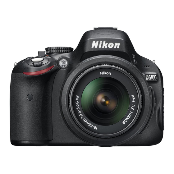
Summary of Contents for Nikon D5100
- Page 1 VBA31001-R.3825.A 作成承認印 配布許可印 サービス 計画課 M VBA31001 logo_Q0640 101206_Gdesign_ito REPAIR MANUAL Copyright © 2011 by Nikon Corporation. All Rights Reserved. 無断転載を禁ず !! Printed in Japan April 2011 User ID:NHK...
-
Page 2: Table Of Contents
Lock.knob.............................D20 Menu/Information.edit.button......................D20 Rear.cover............................D21 3..Top.Cover..............................D22 Microphone............................D22 SB.lock.release.plate..........................D23 Speaker..............................D24 SB.top.cover............................D25 SB.lower.cover.unit..........................D26 AF.assist.lamp.unit..........................D28 Top.cover.FPC.unit..........................D29 Command.dial.unit..........................D30 Exposure.compensation/Movie.record/Information.button..............D30 Power.dial.unit.............................D31 Mode.dial.unit............................D31 Hot.shoe...............................D33 Prism.box.unit............................D34 Screen..............................D35 Super.impose.display.plate........................D35 LCD.unit...............................D36 G7.lens.unit............................D36 4..Sub-frame.............................D38 Main.condenser............................D38 TOGO.PCB.unit...........................D39 IF.cover.unit............................D41 - D5100 - User ID:NHK... - Page 3 Lens.release.button.unit..........................A2 AF.sensor.unit............................A2 Lens.contact.unit............................A3 .Lens.release.SW/F-min.SW........................A4 Bayonet.mount............................A6 SQ.base.unit............................A7 Height.adjustment.of.aperture.lever.......................A8 MG.PCB.unit............................A8 Shutter.plate.unit..........................A10 Adjustment.of.shutter.curtain.speed.....................A14 Inspection and adjustment of flange-back (body-back)...............A17 Image.sensor.unit..........................A18 2..Sub-frame.............................A20 Bottom.plate.unit..........................A20 Sub-frame.............................A21 SZ-DC/DC.PCB.unit..........................A22 IF.PCB.unit............................A23 Battery.box.unit............................A26 IF.cover.unit............................A29 TOGO.PCB.unit...........................A31 - D5100 - User ID:NHK...
- Page 4 TFT.monitor.unit..........................A65 SD.cover.unit............................A70 5..External.Appearance...........................A71 Top.cover.unit............................A71 Adjustment of camera body (except imaging)..................A73 Inspection.and.adjustment.of.camera.body.(except.imaging).required.when.parts.are. replaced..........................A74 Firmware.update...........................A75 How.to.connect.camera.and.PC......................A75 How to install inspection and adjustment software for camera body (except imaging)......A75 Inspection.and.adjustment.for.AE.accuracy..................A75 - D5100 - User ID:NHK...
- Page 5 Image.adjustment.1..........................A90 Image.adjustment.2..........................A90 Image.adjustment.3..........................A90 Image.adjustment.4..........................A91 Image.adjustment.5..........................A93 White (hot/bright) pixel compensation against dark background............A93 Inspection.and.adjustment.of.shutter.via.shot.image................A93 Obtaining.of.reference.value........................A94 Rewriting.the.TFT.initial.value......................A95 Factory.default.setting..........................A95 Confirmation of data..........................A95 Version.no../Serial.no...........................A95 Inspection.standards......................R1 Wiring..........................E1 Mounting.Drawing......................E2 FUSE.arrangement......................E3 Tool.list..........................T1 Screw.sheet.......................... S1 - D5100 - User ID:NHK...
-
Page 6: Disassembly
④ The low-pass filter of the image CCD PCB is easily damaged. Handle it very carefully.. ref...In.this.manual,.the.application.of.grease.and.adhesive.is.indicated.by.coloring.as.follows. CFD-409Z EDB0011 (grease:.yellow/adhesive:.red).or.J-number.. Note:. ①.The.structure.of.this.product.does.not.permit.to.adjust.the.AE-CCD.positioning...Therefore,. disassemble.the.prism.box.unit.up.to.the.stage.shown.from.page.D34.to.D37..and.do.NOT.do.a. further.disassembly... (ref..parts.list) ②.What.are.used.in.this.manual.may.differ.from.the.actual.products.in.forms,.etc. Points.to.notice.for.Lead-free.solder.products • Lead-free.solder.is.used.for.this.product. • For.soldering.work,.the.special.solder.and.soldering.iron.are.required. • Do.not.mix.the.lead-free.solder.with.the.conventional.solder. • Use.the.special.soldering.iron.respectively.for.lead-free.solder.and.lead.solder..They.cannot. be.used.in.common. - D1 ・ D5100 - User ID:NHK... -
Page 7: External.appearance
VBA31001-R.3825.A 1..External.Appearance Rear.cover.unit • Incline the battery cover unit (#B151) at an approx. 35° as below, and remove it. #B151 • Remove the power cable cover (#72). - D2 ・ D5100 - User ID:NHK... - Page 8 L-401 Inside #B1026 • Remove the cover (#267). • Take out the screw (#614). • Take out the screw (#625). • Take out the two screws (#709). #267 #625 #614 #709 × 2 - D3 ・ D5100 - User ID:NHK...
- Page 9 VBA31001-R.3825.A • Take out the three screws (#631). #631×3 • Take out the two screws (#708). • Take out the two screws (#709). #709×2 #708×2 - D4 ・ D5100 - User ID:NHK...
- Page 10 Remove the rubber (#410) and the double-stick tape (#411). • Take out the screw (#622). #410 #411 #622 • Lift.up.the.rear.cover.unit. • Disconnect.the.FPC. • With the tweezers tool (T91316), remove the harness. • Remove.the.rear.cover.unit. Rear.cover.unit Disconnect.the.harness. from.the.TOGO.PCB. T91316 Tweezers.tool - D5 ・ D5100 - User ID:NHK...
-
Page 11: Front.cover.unit
Take out the two screws (#644) and one screw (#639). • Take out the three screws (#631). • Take out the one screw (#643) and two screws (#634). #639 #644 #644 #631×3 #634×2 #643 • Slacken.the.tripod.base.area,.and.remove.the.front.cover.unit. Front.cover.unit - D6 ・ D5100 - User ID:NHK... - Page 12 VBA31001-R.3825.A • Remove the gasket (#583). #583 • Take out the screw (#650). • Remove the remote control window (#463). • Remove the button (#465). =Unhook. #463 #465 #650 - D7 ・ D5100 - User ID:NHK...
- Page 13 VBA31001-R.3825.A • Take out the screw (#661). • Remove the grip cover (#27). #661 • Remove the adhesive (L-401), and then the lens release mark (#25). Back.side L-401 - D8 ・ D5100 - User ID:NHK...
-
Page 14: Discharge.of.main.condenser
You must discharge the main condenser according to the instruction of this repair manual after you remove the cover. 2KΩ/5W Top.cover.unit • Unsolder.the.four.wires.of.the.SB.lower.cover.unit. • Disconnect the harness (#6022). • Unsolder.the.two.wires.of.the.microphone.and.the.two.wires.of.the.speaker... • Disconnect.the.FPC. [Black] Four.wires.of.the.SB.lower.cover.unit [Blue] [Red] [White] #6022 [Gray] [Blue] [Orange] [Green] - D9 ・ D5100 - User ID:NHK... - Page 15 VBA31001-R.3825.A • Take out each screw [(#631), (#632), and (#701)]. #632 #631 #701 • Remove.the.top.cover.unit. Top.cover.unit The kind of lifting " ○ " area will facilitate the removal. - D10 ・ D5100 - User ID:NHK...
-
Page 16: Rear.cover
VBA31001-R.3825.A 2..Rear.Cover SD.cover.unit • Remove the SD cover unit (#B431). =Unhook. #B431 TFT.monitor.unit • Take out the two screws (#624). #624×2 - D11 ・ D5100 - User ID:NHK... - Page 17 VBA31001-R.3825.A • Open the TFT unit, and remove the hinge cover A (#450) and hinge cover B (#451). #451 #450 • Take out the two screws (#704). #704×2 • Remove.the.TFT.unit. TFT.unit Be.careful.NOT.to. catch.the.harness. - D12 ・ D5100 - User ID:NHK...
- Page 18 Turn the hinge unit in the direction of the arrow, and take out the two screws (#703). #703×2 • Take out the two screws (#702). #702×2 • Remove the TFT monitor top cover (#434). #434 ○= Unhook - D13 ・ D5100 - User ID:NHK...
- Page 19 VBA31001-R.3825.A • Turn.the.legs.of.the.hinge.unit.in.the.direction.of.the.arrow. • With the tweezers tool (T91316), remove the harness. • Disconnect.the.two.FPCs. • Unsolder.the.three.wires. T91316 Tweezers.tool [Black] Hinge.unit [Red] [Yellow] • Remove.the.hinge.unit. Hinge.unit • Remove the retainer plate (#406). #406 - D14 ・ D5100 - User ID:NHK...
- Page 20 Turn the fixed plate of the hinge unit in the direction of the arrow as below, and take out the screw (#705). • Remove the hinge cover (#437) from the hinge unit (#B454). #437 #B454 ○= Unhook #705 - D15 ・ D5100 - User ID:NHK...
-
Page 21: Eyepiece
Take out the two screws (#624), and remove the eyepiece frame (#475). • Remove the sponge (#476). #624×2 #476 #475 • Take out the screw (#621). • Remove the retainer plate (#266). • Remove the diopter adj. knob (#265). #265 #266 #621 - D16 ・ D5100 - User ID:NHK... -
Page 22: Rear.sw.fpc.unit
VBA31001-R.3825.A • Take out the screw (#624), and remove the retainer plate (#428). #624 #428 Rear.SW.FPC.unit • Take out the eight screws (#620) and one screw (#624). #620×3 #624 #620×5 - D17 ・ D5100 - User ID:NHK... - Page 23 VBA31001-R.3825.A • Remove the retainer plate (#427). #427 • Remove the rear SW FPC unit (#B5011). #B5011 - D18 ・ D5100 - User ID:NHK...
-
Page 24: Rear.button
#413 #420 #419 #415 #418 #422 #412 SD.access.lamp.window • Remove the adhesive (EDC0021), and then the SD access lamp window (#408). • Remove the rubber (#387) and button (#385). #408 #387 #385 EDC0021 - D19 ・ D5100 - User ID:NHK... -
Page 25: Lock.knob
Lock.knob • Remove the spring (#430) and then the lock knob (#429). #429 #430 Menu/Information.edit.button • Remove the two retainer rings (#389). • Remove the button (#388) and button (#390). #389×2. #388 #390 - D20 ・ D5100 - User ID:NHK... -
Page 26: Rear.cover
Remove the rubber (#443). • Remove the two rubbers (#473). #473×2 #443 • Peel off the tape [TA-0014 (4.4×5.6)], and the double-stick tape (#416). • Peel off the tape (#416). #492 #416 TA-0014 (4.4×5.6) - D21 ・ D5100 - User ID:NHK... -
Page 27: Top.cover
Microphone • Remove the adhesive (L-401), and then the four wires from the guide. L-401 [Blue] [White] [Red] [Black] • Remove the adhesive (C-8008B), and then the microphone (#6018). #6018 C-8008B #6018 #1053 - D22 ・ D5100 - User ID:NHK... -
Page 28: Sb.lock.release.plate
Slip a lumirror sheet (tracing film), etc, into the gap of the pop-up section of the top cover as below, and slide.the.sheet.in.the.direction.of.the.arrow.to.raise.the.section. Lumirror.sheet Approx.. Approx..2cm • Unsolder.the.two.wires. • Take out the screw (#618), and remove the driving magnet (#36). #618 [Black] [White] - D23 ・ D5100 - User ID:NHK... -
Page 29: Speaker
Remove the SB release lever (#456). • Pull out the SB lock lever (#309) in the direction of the arrow, and remove the spring (#458). #458 #456 #309 Speaker • Remove the speaker (#6019). #6019 - D24 ・ D5100 - User ID:NHK... -
Page 30: Sb.top.cover
Take out the two screws (#628). #628×2 • Remove the adhesive (C-8008B) that attaches the inside of the SB top cover, and then remove the SB top cover (#301). #301 C-8008B C-8008B C-8008B - D25 ・ D5100 - User ID:NHK... -
Page 31: Sb.lower.cover.unit
#305 • Remove the four wires from the guide, and peel off the shielding sheet (#585) Guide #585 • Unsolder.the.two.wires. • Remove.the.four.wires.from.the.guides. [Green].or.[Blue] [Green] [Blue] ○= Guide [Gray] [Gray] [Orange] [Orange] [Black] [Red] - D26 ・ D5100 - User ID:NHK... - Page 32 VBA31001-R.3825.A • Pull.out.the.wires. • Remove the roller (#308). Unhook. #308 • While.pulling.the.below.portions.outwards.in.each.direction.of.the.arrow,.remove.the.SB.lower.cover. unit (#B302). #B302 - D27 ・ D5100 - User ID:NHK...
-
Page 33: Af.assist.lamp.unit
Peel off the shielding tape (#586). • Remove.the.two.wires.from.the.guide. • Unsolder.the.four.wires. #6022 Guide #586 [Red] [Black] [Uncoated] [Black] • Take out the screw (#629), and remove the AF assist lamp unit (#B325). #629 #B325 - D28 ・ D5100 - User ID:NHK... -
Page 34: Top.cover.fpc.unit
Remove the five solders of the hot shoe. • Take out the four screws (#617). Solder×5 #617×4 • Remove the top cover FPC unit (#B5010). #B5010 Caution:.When.[#B5010].is.removed,. be.careful.that.the.inner.click.spring. (#361).and.click.ball.(#362).of.the. command.dial.(#B360).may.pop.out. #362 #361 #B360 - D29 ・ D5100 - User ID:NHK... -
Page 35: Command.dial.unit
• Remove the click ball (#362) and the click spring (#361). #362 #361 #B360 Exposure.compensation/Movie.record/Information.button. • Remove the conducting rubber (#382). • Remove each button [(#381), (#383), and (#384)]. #382 #383 #381 #384 - D30 ・ D5100 - User ID:NHK... -
Page 36: Power.dial.unit
#B345 #347 #348 #615×2 Mode.dial.unit • Take out the screw (#616). • Remove the contact brush (#372) and the click spring (#373). • Remove the mode dial unit (#B371). #616 #372 #373 #B371 - D31 ・ D5100 - User ID:NHK... - Page 37 Remove the spring (#376). • Take out the two screws (#663). #376 #663×2 Unhook. • Remove the retainer plate (#375) and the two rubbers (#378). • Remove the LV lever (#374). #375 #374 #378×2 - D32 ・ D5100 - User ID:NHK...
-
Page 38: Hot.shoe
Take out the four screws (#627). • Remove the holder plate (#322), the hot shoe mold unit (#B317), the hot shoe (#316), and the hot shoe spring (#318). #316 #318 #B317 #322 #627×4 #322 #627×4 - D33 ・ D5100 - User ID:NHK... -
Page 39: Prism.box.unit
VBA31001-R.3825.A Prism.box.unit Note:. T he.structure.of.this.product.does.not.permit.to.adjust.the.AE-CCD.positioning...Therefore,. disassemble.the.prism.box.unit.up.to.the.stage.shown.from.page.D34.to.D37..and.do.NOT.do. a.further.disassembly...(ref..parts.list) • Disconnect.the.two.FPCs. • Take out the two screws (#613). #613×2 • Remove.the.prism.box.unit. .Prism.box.unit - D34 ・ D5100 - User ID:NHK... -
Page 40: Screen
VBA31001-R.3825.A Screen #284 #280 #297A.or.#297B Super.impose.display.plate • Remove the rubber (#281). • Remove the super impose display plate (#13B). • Peel off the two rubbers (#285). Caution:.. T he.super.impose.display.plate.(#13B).tends.to.be.scratched.easily,.so.do.NOT.wipe.it.out. with.alcohol...If.dusts.are.attached,.blow.them.with.a.blower. #281 #285×2 #13B - D35 ・ D5100 - User ID:NHK... -
Page 41: Lcd.unit
#650×2. G7.lens.unit • Disconnect the FPC of the AE-CCD from the shading plate (#271) in numeric order from ①.to.② . • Peel off the double-stick tape [TA-0026 (4.5×4.5)]. ① ② TA-0026 (4.5×4.5) #271 - D36 ・ D5100 - User ID:NHK... - Page 42 VBA31001-R.3825.A • Remove the shading plate (#271) and sponge (#293). = Unhook. #271 #293 • Pull out the pin (#262). • Remove.the.G7.lens.unit. Pushing.from.the.prism. side.will.make.it.easier. #262 to.pull.out.[#262]. Remove.from.the. groove.side. Be.careful.of.pop- out.of.the.spring. G7.lens.unit #264 #268 - D37 ・ D5100 - User ID:NHK...
-
Page 43: Sub-Frame
VBA31001-R.3825.A 4..Sub-frame Main.condenser • Peel off the tape [TA-0015 (13×28)]. • Unsolder.the.two.wires. [Blue] [Orange] TA-0015 (13x28) • Peel off the radiating sheet (#77). - D38 ・ D5100 - User ID:NHK... -
Page 44: Togo.pcb.unit
Remove the sponge (#80). #6004 TOGO.PCB.unit • Peel off the gasket (#579). • Take out the two screws (#656) and two screws (#650). • Remove the shield plate (#486A). ○= Unhook #656×2 #650×2 #579 #486A - D39 ・ D5100 - User ID:NHK... - Page 45 Disconnect the four FPCs and harness (#6021). • Take out the screw (#656). #6021 Back.side #656 • Peel off the tape (#498A). • Disconnect the connection-FPC (#5016). • Remove the TOGO PCB unit (#B5001). #B5001 #5016 #498A Be.careful.of.the.terminals. of.the.TOGO.PCB. - D40 ・ D5100 - User ID:NHK...
-
Page 46: If.cover.unit
Take out the one screw (#633) and two screws (#656). • Remove.the.IF.cover.unit. #656×2 IF.cover.unit #633 • Take out the screw (#601), and remove the shield plate (#481). • Remove the IF cover (#71) from the I/F cover (#70). #481 #601 - D41 ・ D5100 - User ID:NHK... -
Page 47: Battery.box.unit
VBA31001-R.3825.A Battery.box.unit • Peel off the tape [TA-0016 (8×25)]. TA-0016 (8×25) • Remove the spring (#158). #158 • Take out the one screw (#638) and two screws (#643). #643×2 #638 - D42 ・ D5100 - User ID:NHK... - Page 48 VBA31001-R.3825.A • With.the.battery.box.unit.being.slanted,.remove.the.FPC. Battery.box.unit • Unsolder.the.eight.wires. • Remove the harness (#6023). • Remove.the.battery.box.unit. #6021 [Red] [Red] [Blue] [Black] [Purple]x2 #6023 Battery.box.unit [Orange] [Blue] - D43 ・ D5100 - User ID:NHK...
- Page 49 • Remove the power drive PCB unit (#B5004RP). #658×2. #664 #B5004RP #1004 • Remove the "O"-ring (#147). • Take out the two screws (#651), and remove the eyelet (#145). #651×2 #145 #651 #147 - D44 ・ D5100 - User ID:NHK...
- Page 50 Take out the screw (#643), and remove the retainer plate (#562), shaft (#563), spring (#564), and the battery stopper hook (#561). #561 #564 #563 #562 #643 • Remove the GND plate (#159). #159 • Peel off the sheet (#154). #154 - D45 ・ D5100 - User ID:NHK...
-
Page 51: If.pcb.unit
VBA31001-R.3825.A IF.PCB.unit • Disconnect.the.FPC. • Take out the two screws (#635). #635×2 • Take out the three screws (#656). #656×3 - D46 ・ D5100 - User ID:NHK... - Page 52 VBA31001-R.3825.A • Remove.the.sub-frame.unit.. Sub-frame.unit • Take out the screw (#656). • Remove.the.IF.PCB.unit. IF.PCB.unit #656 - D47 ・ D5100 - User ID:NHK...
- Page 53 #147 • Take out the two screws (#656), and remove the retainer plate (#65). #656×2 • Remove the gasket (#573) and the shield plate (#482). • Disconnect the connection-FPC (#5015). #573 #482 #5015 - D48 ・ D5100 - User ID:NHK...
-
Page 54: Sz-Dc/Dc.pcb.unit
Remove the SZ-DC/DC PCB unit (#B5003). • Disconnect the connection-FPC (#5017). • Unsolder.the.four.wires. TA-0015 (13×28) [Red] [Black] #B5003 [Purple].x2 #5017 Back.side #656×2 Sub-frame • Remove the two rubbers (#63) from the sub-frame (#62). #63×2 - D49 ・ D5100 - User ID:NHK... -
Page 55: Bottom.plate.unit
Take out the two screws (#647), and remove the bottom plate unit. #647×2 Bottom.plate.unit • Take out the four screws (#630), and remove the bottom plate (#61) from the tripod base (#68). #630×4 - D50 ・ D5100 - User ID:NHK... -
Page 56: Front.body
Take out the three screws (#611). • Remove the image sensor unit (#B3051). #611×3 • Remove the three washers [selected from (#87) to (#107)]. #B3051 Washer (#87-#107)×3 The.thickness.of.the.washers.differs. depending.on.their.attached.locations,.so. remember.correctly.where.each.washer. used.to.be.attached. • Unsolder.the.three.wires. [Red] [Gray] [Black] - D51 ・ D5100 - User ID:NHK... -
Page 57: Shutter.plate.unit
Shutter.plate.unit • Turn the gear (indicated in red) of the SQ base unit in the direction of the arrow to raise the mirror. Then,.set.the.lever's.position.of.the.MG.PCB.unit.to.the."OK".position.as.below. Caution:.It.may.need.several.turns.of.the.gear.to.become.at."OK".position. SQ.base.unit levers NG: Not Good NG: Not Good - D52 ・ D5100 - User ID:NHK... - Page 58 Remove the retainer plate (#2004). #2004 #612 • Take out the two screws (#612). • Remove the brake plate (#196). #612×2 #196 • Take out the screw (#604). • Remove the retainer plate (#2003). #604 #2003 - D53 ・ D5100 - User ID:NHK...
- Page 59 VBA31001-R.3825.A • Take out the screw (#608). • Remove the holder plate (#2002). Caution:.Be.careful.that.the.spring.may.pop.out...To.avoid.deformation.of.[#2002],.do.NOT.hold. the.other.areas.than.indicated.in.red. • Unhook the springs (#178 and #179). #608 #2002 = Unhook. #179 #178 - D54 ・ D5100 - User ID:NHK...
- Page 60 VBA31001-R.3825.A • Remove the shutter curtain unit (#B2016), and spring (#178). #B2016 #178 • Remove the retainer plate (#2015). #2015 - D55 ・ D5100 - User ID:NHK...
- Page 61 VBA31001-R.3825.A • Remove the shutter curtain unit (#B2016), and spring (#179). #B2016 #179 • Take out the screw (#619). • Remove the shutter plate unit (#2001RP). Caution:.To.avoid.deformation.of.[#2001RP],.do.NOT.hold.the.other.areas.than.indicated.in.red. #619 #2001RP - D56 ・ D5100 - User ID:NHK...
-
Page 62: Mg.pcb.unit
VBA31001-R.3825.A MG.PCB.unit • Unsolder.the.four.wires. [Black] [Red] • Take out the two screws (#607). • Remove the MG PCB unit (#B176). #607×2 #B176 - D57 ・ D5100 - User ID:NHK... -
Page 63: Sq.base.unit
• Turn.the.gear.indicated.in.red.clockwise.to.lower.the.mirror. • Loosen the four screws (#602). By slightly lifting the SQ base unit, remove the spring of the SQ unit from.the.hook.of.the.mirror.unit. • Take out the four screws (#602). #602×2 #602×2 Spring - D58 ・ D5100 - User ID:NHK... -
Page 64: Bayonet.mount
Peel off the shading sheet (#29). #B2177 Bayonet.mount • Take out the five screws (#653) and one screw (#654). • Remove the bayonet mount (#111). • Remove the three bayonet springs (#112). #653×5 #112×3 #654 #111 - D59 ・ D5100 - User ID:NHK... -
Page 65: F-Min.sw/Lens.release.sw
Remove the solder bridge that joints the GND plate (#138) and the FPC of the lens contact unit (#B2113). • Take out the two screws (#650), and remove the GND plate (#138). #650×2 #138 #B2113 Remove.solder bridge. #668 #133 Remove.solder bridge. - D60 ・ D5100 - User ID:NHK... -
Page 66: Lens.contact.unit
VBA31001-R.3825.A • Take out the screw (#652). • Remove the lens release SW (#121). #652 #121 Lens.contact.unit • Remove the lens contact unit (#B2113) and sheet (#114A). #B2113 #114A - D61 ・ D5100 - User ID:NHK... -
Page 67: Af.sensor.unit
Remove the three springs (#161). #162×3 #B2163 #161×3 Lens.release.button.unit • Take out the two screws (#648). • Remove the lens release PCB (#115), spring (#119), and the lens release button unit (#B116). #115 #648×2 #B116 #119 - D62 ・ D5100 - User ID:NHK... -
Page 68: Mirror.unit
C-8008B #199 C-8008B #198 #B2231 • Peel off the shading sheet (#238), sheet (#239), and sheet (#496). • Take out the two screws (#662), and remove the holder (#30). #238 #662×2 #239 #496 - D63 ・ D5100 - User ID:NHK... -
Page 69: Assembly
Mount the mirror unit (#B2231), and attach the main mirror shafts (#198 and #199). • Apply the adhesive (C-8008B) to these main mirror shafts (#198 and #199). Application.range C-8008B #199 C-8008B #198 #B2231 - A1 ・ D5100 - User ID:NHK... -
Page 70: Lens.release.button.unit
Attach the three springs (#161). • Mount the AF sensor unit (#B2163). • Turn the three screws (#162) all the way with the hexagonal key (φ1.5mm) but not too tightly, and then give.each.screw.two.turns.counterclockwise. #162×3 #B2163 #161×3 - A2 ・ D5100 - User ID:NHK... -
Page 71: Lens.contact.unit
Make a crease on the FPC of the lens contact unit (#B2113) as below. Mountain-fold Mountain-fold Valley-fold #B2113 • Mount the lens contact unit (#B2113) and sheet (#114A). #B2113 Position.for.mounting.[#114A] #114A =Boss =Guide - A3 ・ D5100 - User ID:NHK... -
Page 72: Lens.release.sw/F-Min.sw
Tighten the screw (#652). • Attach the two pieces of the shield sheet (#582) to the FPC’s both surfaces (of the same position) of the lens contact unit (#B2113). Attaching.position =Boss =Guide #582 #652 #121 #582 - A4 ・ D5100 - User ID:NHK... - Page 73 Mount the GND plate (#138), and tighten the two screws (#650). • Make a solder bridge that connects the GND plate (#138) and the FPC of the lens contact unit (#B2113). #650×2 #138 Make.solder.bridge. - A5 ・ D5100 - User ID:NHK...
-
Page 74: Bayonet.mount
Mount the bayonet mount (#111). • Tighten the five screws (#653) and one screw (#654) in numeric order from ①.to.⑥ . ⑤ ③ ② #112×3 #653×5 #654 ④ ⑥ ① LEN317A #111 TNG-87 - A6 ・ D5100 - User ID:NHK... -
Page 75: Sq.base.unit
Tighten the four screws (#602) temporarily. • With.the.SQ.unit.being.lifted.slightly,.hook.the.spring.to.the.mirror.unit. • Do final tightening of the four screws (#602) in numeric order from ①.to.④ . • After.assembling.the.above,.check.whether.the.aperture.lever.section.works.smoothly. ④ ② #602×2 #602×2 Direction.for. positioning ③ Spring ① - A7 ・ D5100 - User ID:NHK... -
Page 76: Height.adjustment.of.aperture.lever
J18004 Aperture.lever.positioning.gauge MG.PCB.unit • Turn the gear (indicated in red) of the SQ base unit in the direction of the arrow to raise the mirror. Then,.set.the.lever's.position.of.the.MG.PCB.unit.to.the."OK".position.as.below. Caution:.It.may.need.several.turns.of.the.gear.to.become.at."OK".position. SQ.base.unit lever's (Not Good) (Not Good) - A8 ・ D5100 - User ID:NHK... - Page 77 Tighten the two screws (#607) in numeric order from ①.to.② . • After the above tightening, check whether the lever of the MG PCB unit (#B176) works smoothly. #607×2 ① ② #B176 • Solder.the.four.wires. [Black] [Red] - A9 ・ D5100 - User ID:NHK...
-
Page 78: Shutter.plate.unit
Apply the grease (RX-4552) to the MG PCB unit (#B176). • Mount the shutter plate unit (#2001RP). Caution:.. T o.avoid.deformation.of.[#2001RP],.do.neither.hold.the.other.areas.than.indicated.in.red,. nor.let.[#2001RP].be.placed.on.the.shaft. • Tighten the screw (#619). RX-4552 #619 #2001RP Direction.for. positioning [#2001RP].must.not. be.placed.on.the.shaft. - A10 ・ D5100 - User ID:NHK... - Page 79 Attach the spring (#179). (At this point, do NOT engage the hook.) • Mount the retainer plate (#2015). This.circle.must.face. the.penta.prism.side. #2015 #B2016 #179 • Attach the spring (#178). • Mount the shutter curtain unit (#B2016). #B2016 #178 - A11 ・ D5100 - User ID:NHK...
- Page 80 VBA31001-R.3825.A • Hook the spring (#178) and spring (#179). • Mount the holder plate (#2002). Caution:.Be.careful.that.the.spring.may.pop.out...To.avoid.deformation.of.[#2002],.do.NOT.hold. the.other.areas.than.indicated.in.red. • Tighten the screw (#608). #608 #2002 = Hook. #179 #178 - A12 ・ D5100 - User ID:NHK...
- Page 81 #604 = Boss #2003 • Mount the brake plate (#196), and tighten the two screws (#612). Direction.for. positioning #612×2 #196 • Mount the retainer plate (#2004), and tighten the screw (#612). #2004 #612 - A13 ・ D5100 - User ID:NHK...
-
Page 82: Adjustment.of.shutter.curtain.speed
..④ Start the adjustment software for D3100 camera body (except imaging) (J65153), and click "MAKE 3), and click "MAKE ), and click "MAKE. A CURTAIN SPEED ADJ. DUMMY BODY".. ⑤.Select."Yes".. ⑥ Turn.the.camera.OFF,.and.disconnect.the.camera.from.PC.. ⑦.Remove.the.rear.cover.. ⑧.Remove.the.FPC.of.the.SQ.base.unit. - A14 ・ D5100 - User ID:NHK... - Page 83 Rotational. direction Tool (device) J19123 RJ.is. J19123E J19042E J61242 J18267 unavailable EF-1 EF-8000 For.EF-1 For.EF-8000 Curtain.speed.adjuster LENS AF50/1.4D Shutter.tester T.V..Measuring.adapter Use Nikon product. J61245 Power.supply Power.connector. AC.adapter Curtain.speed.adj.. (10V 5A) EP-5A EH-5.or.EH-5A dummy.body - A15 ・ D5100 - User ID:NHK...
- Page 84 VBA31001-R.3825.A • Bend the FPC of the SQ base unit (#B2177) as below. Place.under.the.front.body.unit. - A16 ・ D5100 - User ID:NHK...
-
Page 85: Inspection And Adjustment Of Flange-Back (Body-Back)
1K106-565 washer.T=0.17 100 1K106-566 washer.T=0.18 101 1K106-567 washer.T=0.19 102 1K106-568 washer.T=0.20 103 1K106-569 washer.T=0.21 104 1K106-570 washer.T=0.22 105 1K106-571 washer.T=0.23 106 1K106-572 washer.T=0.24 107 1K106-573 washer.T=0.25 Tool (Device) J19004-1 J18001-1 J11388 Dial.indicator.and.stand Body-back.focus.gauge Flat-type.measuring.terminal - A17 ・ D5100 - User ID:NHK... -
Page 86: Image.sensor.unit
Mount the image sensor unit (#B3051). • Tighten the three screws (#611) in numeric order from ①.to.③ . • Attach the tape (#59). #611×3 ① ③ Direction.for. ② positioning Attaching.position Attaching.position #B3051 Place.the.tape.under.the.tip. of.the.screw. - A18 ・ D5100 - User ID:NHK... - Page 87 Pass the wires of the harness (#6023) through the ferrite core (#6013), and wrap the wires around [#6013] once.as.below. 16±1mm #6013 #6023 • Solder.the.three.wires. [Red] [Gray] [Black] • Arrange.the.wires.as.below. Place.under.the.FPC.of.the. The.wires.must.NOT.be.placed.on. SQ.base.unit. the.4.terminals. Push.the.3.wires.into. the.gap. #6023 - A19 ・ D5100 - User ID:NHK...
-
Page 88: Sub-Frame
8 ± 1 • Place.the.two.wires.as.below,.and.mount.the.bottom.plate.unit. Tighten the two screws (#647) in numeric order from ①.to.② . • #647×2 ① ② Place.in.the.back.of.the.AF.sensor.FPC. Be careful NOT to block the YAW PITCH adj hole. YAW PITCH 調整穴を塞がないよう注意 Bottom.plate.unit - A20 ・ D5100 - User ID:NHK... -
Page 89: Sub-Frame
VBA31001-R.3825.A Sub-frame • Attach the tape [TA-0016 (7×23)] to the sub-frame (#62). Fold.backwards. Attaching.position TA-0016 (7×23) • Attach the two rubbers (#63) to the sub-frame (#62). #63×2 CFD-409Z Dipping - A21 ・ D5100 - User ID:NHK... -
Page 90: Sz-Dc/Dc.pcb.unit
Mount the SZ-DC/DC PCB unit (#B5003). • Tighten the two screws (#656). • Connect the connection-FPC (#5017). [Red] [Black] #B5003 [Purple].x2 #5017 Back.side #656×2 • Attach the tape [TA-0015 (13×28)]. Attach.by.covering. each.corner. TA-0015 (13×28) Attaching.position - A22 ・ D5100 - User ID:NHK... -
Page 91: If.pcb.unit
#5015 (central).line.of.the.connector. • Mount the plate (#65), and tighten the two screws (#656). #656×2 • Mount the eyelet (#145), and tighten the two screws (#657). • Mount the "O"-ring (#147). #657×2 #145 #147 - A23 ・ D5100 - User ID:NHK... - Page 92 VBA31001-R.3825.A • Mount the IF PCB unit, and tighten the screw (#656). IF.PCB.unit #656 • Mount.the.sub-frame.unit. Sub-frame.unit Assembled - A24 ・ D5100 - User ID:NHK...
- Page 93 EDB0011 ③ ① ② • Tighten the two screws (#635) with the torque driver (set value: 12N.cm).in.numeric.order.from.①.to.② . • Connect the FPC (#5017) to the image sensor unit (#B3051). #635×2 ① ② #5017 - A25 ・ D5100 - User ID:NHK...
-
Page 94: Battery.box.unit
Mount the GND plate (#159). = Boss #159 • Mount the battery stopper hook (#561), spring (#564), shaft (#563), and the retainer plate (#562). Then, tighten the screw (#643). Boss #561 #564 #563 #562 Boss #643 - A26 ・ D5100 - User ID:NHK... - Page 95 Mount the power drive PCB unit (#B5004RP). • Tighten the two screws (#658) and one screw (#664). #658×2 #664 #B5004RP • Solder.the.eight.wires. • Connect the harness (#6023). #6021 [Red] [Red] [Blue] [Black] [Purple]x2 #6023 [Orange] [Blue] - A27 ・ D5100 - User ID:NHK...
- Page 96 VBA31001-R.3825.A • Connect.the.FPC.with.the.battery.box.being.tilted. Battery.box.unit • Mount.the.battery.box.unit. • Tighten the two screws (#643) and one screw (#638). #643×2 #638 Battery.box.unit • Mount the spring (#158). #158 - A28 ・ D5100 - User ID:NHK...
-
Page 97: If.cover.unit
Attach the IF cover (#71) to the IF cover (#70). • Attach the shield plate (#481), and tighten the screw (#601). #481 #601 • Attach the shielding sheet (#587). #587 #587 Attaching. position - A29 ・ D5100 - User ID:NHK... - Page 98 VBA31001-R.3825.A • Attach the tape [TA-0015 (9×13)]. TA-0015 (9×13) Attaching. position TA-0015 (9×13) • Mount the IF cover unit, and tighten the two screws (#656) and one screw (#633). #656×2 IF.cover.unit #633 - A30 ・ D5100 - User ID:NHK...
-
Page 99: Togo.pcb.unit
Mount the TOGO PCB unit (#B5001). • Twist the two wires of the harness (#6021) five times into a bundle as below. #6021 Give the harness wires five twists. By.slackening.the.four.FPCs.and.harness,. mount.[#B5001]. #B5001 Firstly, fit in the terminal section.of.the.TOGO.PCB. - A31 ・ D5100 - User ID:NHK... - Page 100 Tighten the screw (#656). • Connect the four FPCs and harness (#6021). Arrange.the.wires.without. running.off.the.edge.of.the. battery.box.section. #6021 Back.side #656 • Attach the tape [TA-0020 (12×37)] to the shield plate (#486A). Attaching.position TA-0020 (12×37) Fold.backwards. #486A TA-0020 (12×37) - A32 ・ D5100 - User ID:NHK...
- Page 101 Mount the shield plate (#486A). • Tighten the two screws (#656) and two screws (#650). ○= Hook #656×2 #650×2 #486A • Attach the gasket (#579). Reference. position.for. attaching.[#579] Attaching.surface.of. the.tape Cover.the.2. projections.of.the. plate. #579 - A33 ・ D5100 - User ID:NHK...
-
Page 102: G7.Lens.unit
VBA31001-R.3825.A G7.lens.unit • Mount.the.G7.lens.unit. • Insert the pin (#262). Be.careful.that.the. spring.may.pop.out. G7.lens.unit #264 #268 Inserting.position.of.pin #262 CFD-409Z (Dipping) Put.into.the.groove. • Mount the shading plate (#271) and sponge (#293). Mounting.position #271 #293 - A34 ・ D5100 - User ID:NHK... - Page 103 VBA31001-R.3825.A = Hook. • Attach the double-stick tape [TA-0026 (4.5×4.5)]. • Attach the FPC of the AE-CCD to the shading plate (#271). TA-0026(4.5×4.5) #271 Attaching. position Put.inside.the.guide. • Connect.the.FPC. Put.inside.the.guide. - A35 ・ D5100 - User ID:NHK...
-
Page 104: Lcd.unit
VBA31001-R.3825.A LCD.unit • Attach the tape [TA-0026 (6×11)]. Attaching.position TA-0026 (6×11) • Mount the LCD unit (#B5013). • Tighten the two screws (#650). • Attach the tape (#291). #650×2 Position.for.attaching.[#291] #B5013 #291 - A36 ・ D5100 - User ID:NHK... -
Page 105: Super.impose.display.plate
Mount the super impose display plate (#13B). • Attach the two rubbers (#285), and the other rubber (#281). Caution:.. T he.super.impose.display.plate.(#13B).tends.to.be.scratched.easily,.so.do.NOT.wipe.it.out. with.alcohol...If.dusts.are.attached,.blow.them.with.a.blower. #281 Attaching.position #285×2 #13B Screen Surface.WITH.irregularities.must. #284 #280 face.the.prism.side,.while.surface. WITHOUT.irregularities.must.face. front.body. #297A.or.#297B - A37 ・ D5100 - User ID:NHK... -
Page 106: Prism.box.unit
VBA31001-R.3825.A Prism.box.unit • Mount.the.prism.box.unit. • Tighten the two screws (#613). Direction.for. positioning #613×2 • Connect.the.two.FPCs. Be.careful.NOT.to.connect.the.FPCs. diagonally.to.the.connector. - A38 ・ D5100 - User ID:NHK... -
Page 107: Angle.adjustment.of.main.mirror.and.sub-Mirror
Sub-mirror.adj.. Main Sub.(51°) eccentric.pin Up-down.deviation 0±3′ 0±4′ Main.mirror.adj.. Left-right.deviation 0±25′ .. eccentric.pin ※ Height.indication.position.of.the. measurement-use.sub-mirror. Tool (Device) J19132 J19132D J15442 Main/Sub.mirror.angle.inspection.tool 54°-measurement-use mirror Reflection mirror Main.condenser • Attach the sponge (#80). Attaching.position - A39 ・ D5100 - User ID:NHK... - Page 108 Put the main condenser unit (#6004) firmly on the sponge (#80), and while positioning it by pulling in the.direction.of.the.arrow,.mount.it. • Attach the radiating sheet (#77). #6004 Attach.with.a.slight. #6004 slackness. Direction.for. ガタ寄せ方向 positioning Attach.by.aligning.the. edge.of.the.double-stick. tape.(#141).with.the.dot. line... - A40 ・ D5100 - User ID:NHK...
-
Page 109: Inspection.for.ae-Ccd.positioning
• Mount the front cover (#24), and tighten the three screws (#631) (for temporary assembly). • Refer to "Inspection and adjustment for AE-CCD positioning" of ADJUSTMENT Separate Volume ②. for.details. #631×3 - A41 ・ D5100 - User ID:NHK... - Page 110 There are high voltage parts inside. Be careful of electric shock, when you remove the cover. You must discharge the main condenser according to the instruction of this repair manual after you remove the cover. • Discharge.the.main.condenser. 2KΩ/5W - A42 ・ D5100 - User ID:NHK...
-
Page 111: Top.cover
Attach the holder plate (#322), hot shoe mold unit (#B317), hot shoe (#316), and hot shoe spring (#318). • Tighten the four screws (#627). #316 #318 #B317 #322 #627×4 Mode.dial.unit • Mount the LV lever (#374). NKS-401H #374 GN-20SB - A43 ・ D5100 - User ID:NHK... - Page 112 VBA31001-R.3825.A • Attach the two rubbers (#378). • Attach the retainer plate (#375). #375 = Boss #378×2 • Tighten the two screws (#663). • Attach the spring (#376). #376 #663×2 Hook. - A44 ・ D5100 - User ID:NHK...
-
Page 113: Power.dial.unit
Attach the power dial unit (#B345) with its position being "ON", and then attach the ON-OFF click spring (#347) and ON-OFF SW brush (#348). • Tighten the two screws (#615). #B345 #B345 GN-20SB #347 = Boss #348 #615×2 Back.side - A45 ・ D5100 - User ID:NHK... -
Page 114: Exposure.compensation/Movie.record./Information.button
• Attach each button [(#381), (#383), and (#384)]. • Attach the conducting rubber (#382). #382 #383 #381 #384 #383 #381 #384 Assembled Command.dial.unit • Mount the command dial unit (#B360). GN-20SB #B360 Back.side - A46 ・ D5100 - User ID:NHK... -
Page 115: Top.cover.fpc.unit
Put the click spring (#361) by inserting ① -side first, and then put ② -side.by.following.the.direction.of. the.arrow. #362 #361 GN-20SB Dipping ② ① Top.cover.FPC.unit • Attach the grease (PL-CJ10) to the pattern surface of the top cover FPC unit (#B5010). PL-CJ10 #B5010 - A47 ・ D5100 - User ID:NHK... - Page 116 Mount the top cover FPC unit (#B5010). #B5010 Boss When.mounting.[#B5010],.be. careful.that.the.inner.click.spring. (#361).and.the.click.ball.(#362).of. . the.command.dial.(#B360).may. pop.out. #361 #362 Boss #B360 • Tighten the four screws (#617). • Make five solders to connect the contacts of the hot shoe. #617×4 Make.solder.×5 - A48 ・ D5100 - User ID:NHK...
-
Page 117: Af.assist.lamp.unit
Mount the AF assist lamp unit (#B325), and tighten the screw (#629). #629 #B325 • Solder the four wires, and attach the shielding tape (#586). #6022 Guide [Red] [Black] [Uncoated] [Black] #586 Attaching.position - A49 ・ D5100 - User ID:NHK... -
Page 118: Sb.lower.cover.unit
VBA31001-R.3825.A SB.lower.cover.unit Mount the SB lower cover unit (#B302) , w hile.pulling.the.below.portions.outwards.in.each.direction.of. • the.arrow. #B302 CFD-409Z CFD-409Z • Attach the roller (#308). Hook. CFD-409Z Dipping #308 - A50 ・ D5100 - User ID:NHK... - Page 119 As below, arrange the wires and pass them through the hole of the SB lower cover unit (#B302). • Arrange.the.four.wires.as.below. • Solder.the.two.wires. Either.one.can.be.put.on. the.other. [Green].or.[Blue] [Green] [Blue] [Gray] Guide [Gray] [Orange] [Orange] Guide [Black] [Red] - A51 ・ D5100 - User ID:NHK...
- Page 120 #585 #585 Bundle.and.put.the.4.wires.in.the. center.of.[#585].and.fold.it.as.above. • Attach the spring (#305) by fitting in the groove. • Attach the spring (#459). #B302 • Hook the spring (#305). #459 #305 Put.the.tip.of.[#459].in.the.hole.of.the. Groove SB.lower.cover.unit.(#B302). Hook #305 #459 - A52 ・ D5100 - User ID:NHK...
-
Page 121: Sb.upper.cover
Apply the adhesive (C-8008B) to the SB upper cover (#301) and the SB lower cover unit (#B302) . • Mount the SB upper cover (#301). #301 C-8008B C-8008B C-8008B • Tighten the two screws (#628). #628×2 - A53 ・ D5100 - User ID:NHK... -
Page 122: Speaker
Arrange.the.two.wires.of.the.speaker.as.below. #6019 SB.lock.release.plate • Attach the spring (#458) to the SB lock lever (#309). • Attach the SB lock lever (#309) on the top cover unit. #458 CFD-409Z Dipping #309 Hook here. CFD-409Z - A54 ・ D5100 - User ID:NHK... - Page 123 While hooking the top cover FPC unit (#B5010) in numeric order from ①.to.③ ,.mount.the.SB.lock. release plate (#455). #617×3 • Tighten the three screws (#617). #455 ① ③ ② The tip of [#458] must fit in the " ". ○ (indicated.in.red).of.the.SB.lock.release. plate.(#455).as.below. #B5010 - A55 ・ D5100 - User ID:NHK...
- Page 124 VBA31001-R.3825.A • Attach the driving magnet (#36), and tighten the screw (#618). • Solder.the.two.wires. #618 [Black] [White] • Attach the microphone (#1053). #6018 #6018 - A56 ・ D5100 - User ID:NHK...
- Page 125 VBA31001-R.3825.A • Arrange the wires as below, and apply the adhesive (L-401). L-401 [Blue] [White] [Red] [Black] Arrange.the.4.wires.between.the. boss.and.guide. • Apply the adhesive (C-8008B) to the microphone (#6018). C-8008B - A57 ・ D5100 - User ID:NHK...
-
Page 126: Rear.cover
VBA31001-R.3825.A 4..Rear.Cover Rear.cover • Attach the tape [TA-0014 (4.4×5.6)], and the double-stick tape (#492). #492 TA-0014 (4.4×5.6) Position.for.attaching.[TA-0014] • Attach the tape (#416). Position.for.attaching.[#416] #416 - A58 ・ D5100 - User ID:NHK... - Page 127 VBA31001-R.3825.A • Attach the two rubbers (#473). #473×2 • Attach the rubber (#443). #443 - A59 ・ D5100 - User ID:NHK...
-
Page 128: Menu/Information.edit.button
Attach the two retainer rings (#389). #389×2. #388 #390 Lock.knob • Attach the lock knob (#429). • Attach the spring (#430) by putting it in the protrusion of the lock knob (#429) as below. #429 #430 - A60 ・ D5100 - User ID:NHK... -
Page 129: Sd.access.lamp.window
Attach the multi-selector (#412). • Attach each button [(#422), (#415), (#418), (#419), and (#420)]. • Attach the multi-selector rubber (#413). #413 #420 #419 #415 #418 #422 #422 #415 #412 #412 #418 #420 #419 Assembled - A61 ・ D5100 - User ID:NHK... -
Page 130: Rear.sw.fpc.unit
VBA31001-R.3825.A Rear.SW.FPC.unit • Mount the rear SW FPC unit (#B5011). #B5011 = Boss • Attach the retainer plate (#427). #427 - A62 ・ D5100 - User ID:NHK... -
Page 131: Eyepiece
VBA31001-R.3825.A • Tighten the eight screws (#620) and one screw (#624). #620×3 #624 #620×5 Eyepiece • Attach the retainer plate (#428), and tighten the screw (#624). #624 #428 - A63 ・ D5100 - User ID:NHK... - Page 132 CFD-409Z #265 #266 #621 • Attach the sponge (#476) to the eyepiece frame (#475). • Mount the eyepiece frame (#475) on the rear cover, and tighten the two screws (#624). #624×2 #476 #475 - A64 ・ D5100 - User ID:NHK...
-
Page 133: Tft.monitor.unit
Turn the fixed plate of the hinge unit (#B454) in the direction of the arrow, and tighten the screw (#705). #437 #B454 ○= Hook #705 • Mount the TFT monitor unit (#B5006RP) on the TFT monitor bottom cover (#435RP). #B5006RP #435RP Direction.for.positioning = Press.on.the.sponge. - A65 ・ D5100 - User ID:NHK... - Page 134 VBA31001-R.3825.A • Mount the retainer plate (#406). #406 Pass.the.FPC.through.the. hole.of.[#406]. • Turn.the.two.legs.of.the.hinge.unit.in.the.direction.of.the.arrow,.and.mount.the.hinge.unit. Hinge.unit • Solder.the.three.wires. • Connect.the.two.FPCs.and.harness. [Black] [Red] [Yellow] - A66 ・ D5100 - User ID:NHK...
- Page 135 Mount the TFT monitor top cover (#434). #434 • Turn the hinge unit in the direction of the arrow, and tighten the two screws (#703). #703×2 • Tighten the two screws (#702). #702×2 - A67 ・ D5100 - User ID:NHK...
- Page 136 Attach the spacer (#494) and sensor magnet (#490) on the TFT monitor bottom cover (#435RP). #490 #494 #435RP • Attach the double-stick tape (#403), and mount the TFT window (#402). Direction.for.positioning #402 #403 Attaching.position • Mount.the.TFT.unit. TFT.unit Put the harness first. - A68 ・ D5100 - User ID:NHK...
- Page 137 Arrange the harness as below, and tighten the two screws (#704). #704×2 Arrangement.position.of.harness Direction.for.positioning • Open the TFT unit, and attach the hinge cover A (#450) and hinge cover B (#451). #451 #450 • Tighten the two screws (#624). #624×2 - A69 ・ D5100 - User ID:NHK...
-
Page 138: Sd.cover.unit
VBA31001-R.3825.A SD.cover.unit • Mount the SD cover unit (#B431). =Hook #B431 Caution:.When.the.SD.cover.is.closed,.the.shaft.may.be.caught.by.the.click.plate.sometimes..In.this. case,.push.the.shaft.in.the.direction.of.the.arrow. Click.plate Shaft - A70 ・ D5100 - User ID:NHK... -
Page 139: External.appearance
VBA31001-R.3825.A 5..External.Appearance Top.cover.unit • Lay.the.wires.and.FPC.aside.as.below,.and.mount.the.top.cover.unit. • Tighten each screw [(#631), (#632), and (#701)]. #632 #631 #701 - A71 ・ D5100 - User ID:NHK... - Page 140 Solder the four wires of the SB lower cover unit, and connect the harness (#6022). • Arrange.the.wires.as.below. [Gray] [Blue] #6022 [Orange] [Green] Arrange.the.wires.so.that.they.do.NOT. run.off.the.edge.of.the.power.drive.PCB. • Connect.the.FPC. • Solder.the.two.wires.of.the.microphone.and.the.two.wires.of.the.speaker,.then.arrange.the.wires.as. below. Arrange.the.wires.as.below. [Black] [Blue] [Red] [White] - A72 ・ D5100 - User ID:NHK...
-
Page 141: Adjustment Of Camera Body (Except Imaging)
VBA31001-R.3825.A Adjustment of camera body (except imaging) • Lift.up.the.rear.cover.unit,.and.connect.the.FPC.and.harness. • Turn.the.diopter.adjustment.knob.all.the.way.to.the.right,.and.mount.the.rear.cover.unit. • Tighten the screw (#631) and screw (#709) (for temporary assembly). Be.careful.NOT.to.touch.the.discharging.areas.and.condenser. Diopter.adj..knob Rear.cover.unit Insert.the.harness.to. the.TOGO.PCB. #709 #631 - A73 ・ D5100 - User ID:NHK... -
Page 142: Inspection.and.adjustment.of.camera.body.(Except.imaging).Required.when.parts.are. Replaced
○ ○ ○ unit Power.drive. PCB.unit ○ AF.sensor.unit Top.cover.unit. ○ SB.lower.case. unit SZ-DC/ DC.PCB.unit △ ○ Prism.box.unit ○ △ △ ○ SQ.base.unit ○ ○ MG.PCB.unit Front.body. ○ △ ○ ○ ○ unit - A74 ・ D5100 - User ID:NHK... -
Page 143: Firmware.update
70-300/4.5-5.6 70-300/4-5.6D Shutter.tester 70-300mm.lens J18360 Use Nikon product. Use Nikon product. hhhhh Power.supply Digital.meter Flashmeter Standard reflector Converted. Power.connector. (10V 5A) power.connector EP-5A EP-5A J15443 J15444 J63070 J15428 2WAY.level 2WAY.stage Color.viewer AE.CCD.chart. board - A75 ・ D5100 - User ID:NHK... -
Page 144: Inspection.and.adjustment.for.af.accuracy
(BM-3000) J19123 RJ.is.unavailable J18230 Use Nikon product. EF-1 EF-8000 YAW/PITCH.adjustment. Hexagonal.key Power.connector Shutter.tester tool (φ1.5mm) EP-5A J15450 J19124 J18393 J15443 J15444 AF.ACCURACY. Z-light×2 Slant.chart 2WAY.level 2WAY.stage ADJUSTING LENS *Equivalent. AF-S.50/1.4G fluorescent: flicker-less ."Inverter".lighting. - A76 ・ D5100 - User ID:NHK... -
Page 145: Confirmation Of Data
• Refer.to." ⑪ Reset of compensated AF defocus amount" of ADJUSTMENT Separate Volume ②.for. details. Rewriting.of.offset.value.of.AF.adj..lens • Refer.to." ⑫ Rewriting of offset value of AF adj. lens" of ADJUSTMENT Separate Volume ②.for. details. - A77 ・ D5100 - User ID:NHK... - Page 146 Discharge.the.main.condenser. • Take out the screw (#631) and screw (#709). #709 2KΩ/5W #631 • Lift.the.rear.cover.unit. • Disconnect.the.FPC. • With the tweezers tool (T91316), remove the harness. • Remove.the.rear.cover.unit. Rear.cover.unit. Remove.the.harness.from. the.TOGO.PCB. T91316 Tweezers.tool - A78 ・ D5100 - User ID:NHK...
-
Page 147: Front.cover.unit
VBA31001-R.3825.A Front.cover.unit • Attach the lens release mark (#25), and apply the adhesive (L-401). Back.side L-401 • Attach the grip cover (#27). • Tighten the screw (#661). #661 - A79 ・ D5100 - User ID:NHK... - Page 148 VBA31001-R.3825.A • Attach the button (#465). • Attach the remote control window (#463), and tighten the screw (#650). ○ = Hook #463 #465 #650 • Attach the gasket (#583). 1.0mm Attaching.position #583 0.5mm - A80 ・ D5100 - User ID:NHK...
- Page 149 VBA31001-R.3825.A • Slacken.the.tripod.base.area,.and.mount.the.front.cover.unit. Front.cover.unit • While doing positioning in the below direction of the arrow so as NOT to leave a gap, tighten the screw (#644). Direction.for.positioning #644 - A81 ・ D5100 - User ID:NHK...
- Page 150 VBA31001-R.3825.A • Tighten the three screws (#631). • Tighten the screw (#644) and screw (#639). #639 #644 #631×3 • Tighten the two screws (#634) and one screw (#643). #634×2 #643 - A82 ・ D5100 - User ID:NHK...
-
Page 151: Rear.cover.unit
VBA31001-R.3825.A Rear.cover.unit • Lift.up.the.rear.cover.unit,.and.connect.the.FPC.and.harness.. • Turn.the.diopter.adj..knob.all.the.way.to.the.right,.and.mount.the.rear.cover.unit. Diopter.adj..knob Rear.cover.unit Insert.the.harness.to. the.TOGO.PCB. • Tighten the screw (#622). • Attach the double-stick tape (#411) and rubber (#410). #410 #411 #622 - A83 ・ D5100 - User ID:NHK... - Page 152 VBA31001-R.3825.A • Tighten the two screws (#708). • Tighten the two screws (#709). #709×2 #708×2 • Tighten the three screws (#631). #631×3 - A84 ・ D5100 - User ID:NHK...
- Page 153 Apply the adhesive (L-401). and mount the grip rubber unit (#B1026). (Do NOT reuse the grip rubber unit once it has been removed.) L-401 Inside #B1026 • Attach the power cable cover (#72). - A85 ・ D5100 - User ID:NHK...
- Page 154 • Attach the tape (#565) to the battery cover unit (#B151). #565 #B151 #565 Attaching.position • Incline the battery cover unit (#B151) at an approx. 35° as below, and mount it. #B151 MZ-800SEL. - A86 ・ D5100 - User ID:NHK...
-
Page 155: Measurement.of.consumption.current.value
Refer to "Inspection and adjustment of "∞ (infinity)" focus" of ADJUSTMENT Separate Volume ①.for. details. Standard:.Range.fm.-0.06.to.+0.06mm -0.06.or.smaller:.Increase.the.washers.(to.increase.thickness) 297A 1K603-712 washer.T=0.10 297B 1K603-713 washer.T=0.20 +0.06.or.larger:.Decrease.the.washers.(to.reduce.thickness) Tool (Device) J19001 J18010 J15441 ∞ focus collimator F = 600mm Infinity standard lens 50/1.8 Infinity focus adjustment screen - A87 ・ D5100 - User ID:NHK... -
Page 156: Operation.check.of.image.sensor.cleaning
Oscilloscope TIME/DIV 500ms/div .power.supply V/DIV 500mv/div Adjust.so.that.the.wavy.line.is. Use Nikon product. CH1 OFFSET positioned.in.the.center,.and. easily.viewable. Power.connector EP-5A In case judgements are difficult just checking the waveform, send the data to service planning. D5100.OK..e.g - A88 ・ D5100 - User ID:NHK... -
Page 157: Inspection.and.adjustment.of.imaging.required.when.parts.are.replaced
○ unit Power.drive. ○ △ PCB.unit Image.sensor. ○ ○ ○ ○ ○ ○ ○ △ unit TFT.monitor. ○ ○ unit ○ License.sheet ○ SQ.base.unit MG.PCB. ○ unit Front.body. ○ unit * In.other.cases.than.replacements.of.the.parts,.if.users.point.out.problems,.perform.the.image.sensor.cleaning. operations/inspections. - A89 ・ D5100 - User ID:NHK... -
Page 158: Image.adjustment.1
ND filter 8× Imaging.adj..tool.lens Luminance.meter (BM-3000) Image.adjustment.3 • Adjustment item: Sensitivity ratio adjustment • Refer.to."Sensitivity.ratio.adjustment".of." ① Imaging adjustment" of ADJUSTMENT Separate Volume ③.for.details.. Tool (Device) J19123 RJ.is.unavailable. J61185 J63068 EF-1 EF-8000 Imaging.adj..tool.lens Luminance.meter (BM-3000) Shutter.tester - A90 ・ D5100 - User ID:NHK... -
Page 159: Image.adjustment.4
NG: Not Good captured.by.color.adj..body Compare.differences.in. image.data Cause of NG (Not Good) ① Check light source (re. varia- tion.of.brightness,.lamp.deterio- ration, etc). Image.when.the.color. ② Check SG chart (re. deteriora- reference.value.was.obtained;. tion, etc). captured.by.color.adj..body Check/replace Reacquire.the.color.reference. value.by.color.adj..body. Check-completion - A91 ・ D5100 - User ID:NHK... - Page 160 (Suspected body needing repair) Make.adjustments.so.that.the.same.color. can.be.reproduced.as.that.of.the.image. captured.by.D7000.reference.body. Image.captured.by.D7000.reference.body Adjustment-completion Tool (Device) J11374 J61244 J63112 J63113 Jack D3100. Color.adjusting. SG.chart 200×200.mm color.adj..body device J18498 J63066 J63114 J61247 Lens.AF.28/2.8D D1 filter holder Filter.LB120 Software.for. checking.col..adj.. device (DX) - A92 ・ D5100 - User ID:NHK...
-
Page 161: Image.adjustment.5
Refer.to."Pixel.defect.compensation ② ② White (hot/bright) pixel compensation" of " ①.Imaging. adjustment" of ADJUSTMENT Separate Volume ③.for.details.. Inspection.and.adjustment.of.shutter.via.shot.image • Refer.to."Inspection.and.adjustment.of.shutter.via.shot.image".of." ①.Imaging.adjustment".of.. ADJUSTMENT Separate Volume ③.for.details.. Tool (Device) J19123 RJ.is.unavailable J61185 J63068 EF-1 EF-8000 Imaging.adj..tool.lens Luminance.meter (BM-3000) Shutter.tester - A93 ・ D5100 - User ID:NHK... -
Page 162: Obtaining.of.reference.value
Reference value to be obtained for: Sensitivity and Sensitivity ratio/Sensitivity ratio/color adjustment. • Refer.to." ④ Obtaining of reference value" of ADJUSTMENT Separate Volume ③.for.details... ※.. B efore.obtaining.reference.values,.be.sure.to.get.the.color.reference.values.(for.checking.the. color.adj..device).with.the.software.for.checking.color.adj..device.(DX).(J61247)..W ith.the.color.adj..body.for.D3100.(J61244).and.the.software.for.checking.color.adj..device.(DX). (J61247),.obtain.the.color.reference.values.(for.checking.color.adj..device). • Start.the.software.DX.for.checking.color.adj..device. • Click."Obtain.color.reference.value"...By.following.the.instructions.of.the.software,.obtain.the.color. reference.values. - A94 ・ D5100 - User ID:NHK... -
Page 163: Rewriting.the.tft.initial.value
Refer.to." ⑤ Factory default setting" of ADJUSTMENT Separate Volume ③.for.details... Confirmation of data • Refer.to." ⑥ Confirmation of data" of ADJUSTMENT Separate Volume ③.for.details... Version.no../Serial.no. • Refer.to." ⑦ Version number/Serial number" of ADJUSTMENT Separate Volume ③.for.details... - A95 ・ D5100 - User ID:NHK... -
Page 164: Inspection.standards
Distortion: 8' or less Feeling.in.hand Gap of up-mirror in mirror box: None Sub-mirror 51° angle: Up-down 0 ± 20' Sub-mirror.tool Distortion: 8’ or less ∞ Infinity focus ± 100μm Collimator ∞ Focus lens - R1 ・ D5100 - User ID:NHK... - Page 165 1/500 sec. (EV15, F8): 0 ± 0.65EV AF50/1.4D 1/125 sec. (EV12, F5.6): 0 ± 0.5EV ISO100 1/8 sec. (EV6, F2.8): 0 ± 0.5EV Shutter.tester Variation 0.5EV.or.less AE.mode.difference 0.6EV.or.less Metering.mode. 0.3EV.or.less difference Variation.in.continuous. 0.5EV.or.less shooting - R2 ・ D5100 - User ID:NHK...
- Page 166 Operating time: 1700ms or less +0.3Ω 0.3Ω Luminance: EV12 accumulated Consumption current accumulated: 850mAsec or less Lens: AF-S 18-55/3.5-5.6G Release.without.SD.card. Measure.by.digital. Operating time: 200ms or less multi-meter. Consumption current accumulated: 350 mAsec or less - R3 ・ D5100 - User ID:NHK...
- Page 167 ��Playback on TFT for 4 sec. �� Wait Playback on TFT for 4 sec. �� Wait �� Wait .Wait. until half-release timer becomes OFF: 8 sec. Caution) Assuming that the power SW becomes off every.10-frame.release,.perform.ISC.operation... - R4 ・ D5100 - User ID:NHK...
- Page 168 Delete �� Wait 5 mins. �� Wait 5 mins. .Wait.5.mins. ・ Time taken for movie and accumulated time are recorded in the specified EEPROM.area. ・ Temperature: 23℃ ±2℃ ・ ・ Humidity: 50% ±20% - R5 ・ D5100 - User ID:NHK...
- Page 169 Dead (black) pixels: 3 or less (1 or less in "A" section) No 2 consecutive defective pixels found. Total of hot and dead pixels: 3 or less (1 or less in "A" area) Unevenness.of. A/A’ area luminance No noticeable unevenness found (linear/point-like) - R6 ・ D5100 - User ID:NHK...
-
Page 170: Wiring
5004 Microphone Speaker Black 6018 6019 Orange 5003 Main condenser Blue 6004 Connector connection 5001 HINGE unit 5002 Black Yellow 5006 5016 5017 5008 Connector connection 6006 TFT monitor 5018 5011 Soldering bridge - E1 ・ D5100 - User ID:NHK... -
Page 171: Mounting.drawing
Rear cover unit FGND EN-EL14 5006 40pin PCB unit (Rear) 5011 Rear SW-FPC unit (Rear) SZ unit 61pin 5002 HINGE PCB AE/AF PCB unit(Front) AP11 5008 AP11-FPC unit (Front) #5017 element SZ-SZDCDC-FPC 5018 PZT_FPC FGND - E2 ・ D5100 - User ID:NHK... -
Page 172: Fuse.arrangement
秘/ Confidential 2007 Power drive PCB unit (Front side) 1S460-057 Phenomenon.when.FUSE.has.blown.out A面部品配置図 3倍図 The.power.is.not.turned.on. 設計都合のため 承認 11 02 14 1-1設 藤田 担当 11 01 11 硬質基板部組 藤田 名称 図番 1S020-666-2 - E3 ・ D5100 - 石森 写図 枚数 検図 1-1設 User ID:NHK... -
Page 173: Tool.list
ド�イサーフ MZ-800SEL DRYSURF.MZ-800SEL NKS-401H サ�コール NKS-401H SANKOL NKS-401H C-8008B セメダイ� 8008 (黒) CEMEDINE 8008 (BLACK) EDB0011 ネジロッ� (赤) 1401C SCREWLOCK.1401C EDC0021 アロ�アルファ QUICK DRYING GLUE LEN317A グリース LEN317A GREASE LEN317A 汎用品 パーソナルコ�ピュータ USE.MARKETED. PERSONAL COMPUTER PRODUCT. - T1 ・ D5100 - User ID:NHK... - Page 174 T.V. MEASURING ADAPTER (APS) (For EF-1) 京立電機製 又は [OR] 又は [OR] KYORITSU.ELECTRIC J19042E T秒時測定アダプター (APS EF8000 用) T.V. MEASURING ADAPTER (APS) (For EF8000) J63068 輝度計 (BM-3000) LUMINANCE METER BM-3000 汎用品 デジタルマルチメータ USE.MARKETED. Digital meter PRODUCT. - T2 ・ D5100 - User ID:NHK...
- Page 175 54° ° D3.D3X.D700.D5000. 54°MEASUREMENT-USE MIRROR D3100 J15442 反射ミ�ー .D3100 REFLECTION MIRROR 汎用品 ヘ�スキー (φ1.5mm) USE.MARKETED. HEX. KEY WRENCH (φ1.5mm) PRODUCT. J19004-1 イ�ジケータ及びスタ�ド DIAL INDICATOR AND STAND J18001-1 ボディバッ�出し工具 BODY-BACK.FOCUS.GAUGE J11388 フ�ットタイプ測定端子 FLAT-TYPE MEASURING TERMINAL - T3 ・ D5100 - User ID:NHK...
- Page 176 RJ AF照明箱 (J15264 代用) TI-03045 代用工具 TI-03045 RJ AF illuminator box (J15264) is disused. 又は TIE-03045 参照 For.substitutes.refer.to.TIE03045.. Substitute tool (ref. TIE-03045) J18191 AF 調整用× 1 撮像調整用× 1 NDフィルター8× For.AF.adjustment.X1. ND FILTER 8x For.imaging.adjustment. - T4 ・ D5100 - User ID:NHK...
- Page 177 J18499 AF-SVR 70- 300/4.5-5.6 LENS AF-SVR70-300/4.5-5.6 又は [OR] 又は [OR] 工具設定な AF 70- 300/4-5.6D し RJNo.is not LENS AF70-300/4-5.6D available J19124 Z�イト、 または相当品×2 Z-light.or.equivalent.x.2 ※フリッカレス (イ�バーター) 蛍光灯器具 Z-light×2 ※ Equivalent fluorescent: Flicker-less “Inverter“.lighting. - T5 ・ D5100 - User ID:NHK...
- Page 178 FILTER.SP3 J61246 D7000 工具ボディ (撮像用基準ボディ) D7000 TOOL BODY (FOR IMAGING) ACアダプター EH-5 製品転用 AC.ADAPTER.EH-5 USE NIKON PRODUCT. パワーコネ�ターEP - 5A 製品転用 AC ADAPTER CONNECTOR EP-5A USE NIKON PRODUCT. J18360 基準反射布 Standard reflector 1.5M ×1.5M - T6 ・ D5100 - User ID:NHK...
- Page 179 CURTAIN SPEED ADJUSTMENT TOOL J61242B B 交換用幕速アダプター (幕速調整工具用) SPARE.ADAPTER.FOR.SHUTTER- CURTAIN SPEED ADJUSTMENT TOOL J61242C C 交換用接続�リップ (幕速調整工具用) SPARE CONNECTION-CLIP FOR SHUTTERCURTAIN SPEED ADJUSTMENT TOOL J61242D D 交換用中継ケーブル (幕速調整工具用) SPARE.RELAY-CABLE.FOR.SHUTTER- CURTAIN SPEED ADJUSTMENT TOOL - T7 ・ D5100 - User ID:NHK...
- Page 180 J11374 ジャッキ 200 × 200 mm JACK.200×200mm J63114 フィルターLB120 Filter.LB120 J63066 フィルターホルダー FILTER.HOLDER. J63113 SG チャート SG.CHART J63112 色調整装置 付属のフードを使用 COLOR ADJUSTING DEVICE USE.SUPPLIED.HOOD. J15443 2 ウェイ 水準器 2WAY.LEVEL J15444 2 ウェイ ステージ 2WAY.STAGE - T8 ・ D5100 - User ID:NHK...
- Page 181 VBA31001-R.3825.A 新規工具 工具番号 RJ��� ��� 名 称 備 考 New tool Tool No. RJ.rank Name of tool Others J15420 トル�ド�イバー RTD15CN TORQUE DRIVER RTD15CN J15421-1 トル�ド�イバー用ビット V17 TORQUE.DRIVER.BIT.V17 T91316 ピ�セット工具 TWEEZERS.TOOL - T9 ・ D5100 - User ID:NHK...
-
Page 182: Screw.sheet
#628 #629 #617 #615 QUANTITY ASSEMBLY PARTS NAME Mode.dial.unit Hot.shoe Prism.box.unit LCD.unit TOGO.PCB.unit IF.cover.unit Battery.box.unit DISASSEMBLY TYPE OF SCREW #616 #663 #627 #613 #650 #656 #650 #656 #633 #656 #601 #638 QUANTITY ASSEMBLY - S1 ・ D5100 - User ID:NHK... - Page 183 #647 #630 #611 #612 #604 #608 #619 #607 #602 #653 #654 QUANTITY ASSEMBLY Bayonet.mount F-min.&..lens.release.SW AF.sensor.unit Lens.release.button.unit Mirror.unit PARTS NAME DISASSEMBLY TYPE OF SCREW #655 #668 #650 #652 #162 #648 #662 QUANTITY ASSEMBLY - S2 ・ D5100 - User ID:NHK...
Need help?
Do you have a question about the D5100 and is the answer not in the manual?
Questions and answers