
Related Manuals for Ziton ZP2-ER-C


Summary of Contents for Ziton ZP2-ER-C
- Page 1 ZP2 Series Compact Repeater Installation Manual P/N 501-405503-1-11 • REV 01.10 • ISS 14JAN14...
- Page 2 Copyright © 2014 UTC Fire & Security. All rights reserved. Trademarks and ZP2 Series is a trademark of UTC Fire & Security. patents Other trade names used in this document may be trademarks or registered trademarks of the manufacturers or vendors of the respective products.
-
Page 3: Table Of Contents
Content Important information ii Introduction 1 Installation and commissioning 2 Electrical safety 2 Cabinet assembly 3 Cabinet and PCB layout 4 Cabinet installation 5 Recommended cables 9 Connecting to the fire network 9 Connecting inputs 10 Connecting relays 10 Connecting the external power supply 11 Connecting expansion equipment 11 Connecting an external printer 12 Configuration 12... -
Page 4: Important Information
Important information Limitation of liability To the maximum extent permitted by applicable law, in no event will UTCFS be liable for any lost profits or business opportunities, loss of use, business interruption, loss of data, or any other indirect, special, incidental, or consequential damages under any theory of liability, whether based in contract, tort, negligence, product liability, or otherwise. -
Page 5: Introduction
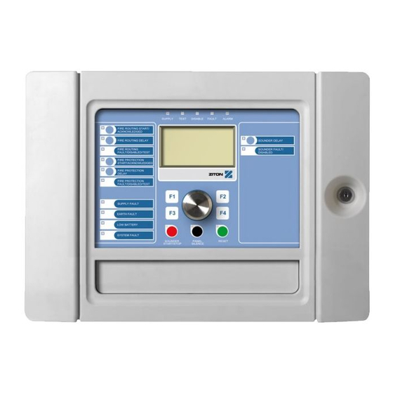
Product range The compact repeater series includes the panels shown below. Table 1: Compact repeater panels Model Description ZP2-ER-C Addressable fire and evacation alarm repeater panel with fire routing and fire protection controls (compact) ZP2-FR-C Addressable fire alarm repeater panel (compact) -
Page 6: Installation And Commissioning
Installation and commissioning This section provides detailed installation, connection, and commissioning information for your control panel. Caution: This product must be installed and maintained by qualified personnel adhering to the CEN/TS 54-14 standard (or the corresponding national standard) and any other applicable regulations. Electrical safety WARNING: Electrocution hazard. -
Page 7: Cabinet Assembly
Cabinet assembly The cabinet assembly is shown below. Remove the cover and the interface to access the PCB. Figure 1: Cabinet assembly ZP2 Series Compact Repeater Installation Manual... -
Page 8: Cabinet And Pcb Layout
Cabinet and PCB layout Figure 2: Cabinet and PCB layout 1. RS-232 connector 8. Local expansion equipment connectors 2. Network connector (fire network) 9. DIN rail locking clips 3. Input connectors 10. USB type A connectors 4. Mounting holes 11. Ethernet connector 5. -
Page 9: Cabinet Installation
Figure 3: Cabinet (back view) 1. DIN rail hook 2. Din rail locking clip Cabinet installation Where to install the control panel Install the control panel in a location that is free from construction dust and debris, and immune to extreme temperature ranges and humidity. Leave enough floor and wall space to allow the control panel to be installed and serviced without any obstructions. - Page 10 Fixing the cabinet to a wall Fix the cabinet to a wall using three M4 × 30 screws and three Ø 6 mm wall plugs, as shown in Figure 4 below. Figure 4: Mounting hole locations To fix the cabinet to a wall: 1.
- Page 11 Fixing the cabinet to a DIN rail The cabinet can also be installed onto a top hat DIN rail (type EN 50022) using the mounting hooks and locking clips provided (see Figure 3 on page 5). To fix the cabinet to a DIN rail: 1.
- Page 12 Adding the menu inserts Add the control panel interface menus as shown below. Figure 6: Adding the menu inserts The inserts are numbered 1, 2, 3, and 4, and are inserted at the location indicated (with the printed area facing the front of the control panel). For evacuation panels, remember to add descriptions for any output groups assigned to the programmable buttons to insert 3.
-
Page 13: Recommended Cables
Recommended cables Recommended cables for optimal system performance are shown in the table below. Table 2: Recommended cables Cable Cable requirements Maximum cable length Power cables 2 × 1.5 mm Fire network cable Twisted-pair, CAT5 1.2 km 28 to 16 AWG (0.08 - 1.5 mm²) Ethernet cable Unshielded CAT5 30 m [1]... -
Page 14: Connecting Inputs
Connecting inputs Connect input switches to IN1 and IN2, as shown in Figure 8 below. For input supervision (open and short circuit), install a 15 kΩ resistor. Figure 8: Connecting inputs If an input is not used, the 15 kΩ end-of-line resistor must be installed across the unused terminals to avoid an open circuit fault on the input. -
Page 15: Connecting The External Power Supply
Connecting the external power supply Connect the external power supply to VIN1, as shown in Figure 10 below. Note: You can connect an optional secondary external power supply to VIN2. In the event of a failure in the primary power supply, the panel will automatically switch to the secondary power supply. -
Page 16: Connecting An External Printer
Connecting remote expansion equipment Connect remote expansion equipment as shown in Figure 12 below. Use the power connector to supply power to remote equipment, if required. Figure 12: Connecting remote expansion equipment Connecting an external printer Connect an external EPSON LX300 printer to RS-232. Note: This option requires the 2010-2-232-KIT (not supplied) to be installed onto the RS-232 connector (see Figure 2 on page 4). -
Page 17: Commissioning
Commissioning After the compact repeater is installed and configured, the panel must be commissioned. Check the following: • That the fire system is designed in accordance with all required regulations and standards • That the maximum alarm current in your installation does not exceed the maximum current specifications of the power supply •... -
Page 18: Maintenance
Maintenance To ensure correct functioning of your control panel and fire alarm system, and compliance with all European regulations, the following maintenance checks should be followed. Caution: Ensure that fire routing (where configured) has been disabled or that the fire brigade has been notified of any planned fire alarm tests. Quarterly maintenance Contact your installation or maintenance contractor to carry out a quarterly inspection of the fire alarm system. -
Page 19: Technical Specifications
Technical specifications Power supply specifications Supply voltage (VIN1, VIN2) Nominal 24 VDC Minimum 20 VDC Maximum 30 VDC Typical current consumption (with no 190 mA at 24 VDC devices connected) LCD specifications Display type 240 x 128 dot graphic LCD (monochromatic) LCD dimensions (L x W) 83 x 44 mm (active area) Backlight type... - Page 20 Configurable inputs Configurable options For configuraton options, see your fire panel installation manual. Relay outputs Number of relay outputs Relay output specification Potential free, NO/NC/C Maximum output current 2 A / 30 VDC Remote equipment outputs Output voltage [1] Supply voltage (VIN1, VIN2) − 1.5 V (for example, 22.5 V at 24 V) Minimum Supply voltage (VIN1, VIN2) −...
- Page 21 Figure 13: Cabinet dimensions ZP2 Series Compact Repeater Installation Manual...
- Page 22 ZP2 Series Compact Repeater Installation Manual...
-
Page 23: Regulatory Information
Regulatory information European standards for electrical safety and electromagnetic compatibility These control panels have been designed in accordance with the following European standards for electromagnetic compatibility: • EN 50130-4 • EN 61000-6-3 • EN 61000-3-2 • EN 61000-3-3 ZP2 Series Compact Repeater Installation Manual... - Page 24 ZP2 Series Compact Repeater Installation Manual...
Need help?
Do you have a question about the ZP2-ER-C and is the answer not in the manual?
Questions and answers