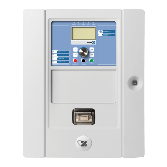
Ziton ZP2 Series Installation Manual
Fire alarm panel
Hide thumbs
Also See for ZP2 Series:
- Operation manual (35 pages) ,
- Protocol manual (15 pages) ,
- Quick operation manual (2 pages)
Table of Contents
Advertisement
Advertisement
Chapters
Table of Contents

Related Manuals for Ziton ZP2 Series


Summary of Contents for Ziton ZP2 Series
- Page 1 ZP2 Series Installation Manual P/N 00-3251-501-0003-04 • ISS 04MAY15...
- Page 2 Copyright © 2015 UTC Fire & Security. All rights reserved. Trademarks and ZP2 Series is a trademark of UTC Fire & Security. patents Other trade names used in this document may be trademarks or registered trademarks of the manufacturers or vendors of the respective products.
-
Page 3: Table Of Contents
Fire alarm system maintenance 110 Battery maintenance 111 Chapter 5 Technical specifications 113 Appendix A Default configurations 123 Appendix B PSTN country codes 125 Appendix C Menu maps 127 Appendix D Regulatory information 137 Index 139 ZP2 Series Installation Manual... -
Page 4: Important Information
Important information Introduction This is the installation manual for the ZP2 Series fire alarm, repeater, and evacuation control panels. Read these instructions and all related documentation entirely before installing or operating this product. Firmware compatibility Information in this document covers control panels with firmware version 3.5 or later. - Page 5 Note: Note messages advise you of the possible loss of time or effort. They describe how to avoid the loss. Notes are also used to point out important information that you should read. ZP2 Series Installation Manual...
- Page 6 ZP2 Series Installation Manual...
-
Page 7: Introduction
This chapter provides an introduction to your control panel, the main controls, and the indicators. Content Product range 2 Product compatibility 3 Product overview 4 The user interface 4 Front panel controls and indicators 6 LCD controls and indicators 10 Acoustic indicators 12 Conditions 12 ZP2 Series Installation Manual... -
Page 8: Product Range
“Firenet configuration” on page 56. Fire routing and fire protection control and indication In this document, information on control and indication for fire routing and fire protection applies only to control panels that include those features. ZP2 Series Installation Manual... -
Page 9: Product Compatibility
Products compatible with these control panels are listed in the supplied compatibility list. Only those products specified in the compatibility list are guaranteed to be compatible with these control panels. For further details contact your local supplier. ZP2 Series Installation Manual... -
Page 10: Product Overview
11. Reset button and LED 23. Fire Routing On/Acknowledged button and 12. Panel Silence button and LED See “Assigning an output group to a programmable button” on page 93 for more information on configuring programmable buttons. ZP2 Series Installation Manual... - Page 11 25. Fire Routing On/Acknowledged button and 12. Jog dial and function buttons 13. Reset button and LED See “Assigning an output group to a programmable button” on page 93 for more information on configuring programmable buttons. ZP2 Series Installation Manual...
-
Page 12: Front Panel Controls And Indicators
On/Acknowledged down and activates fire routing. button and LED A flashing LED indicates that fire routing has been activated. A steady LED indicates that the fire routing signal has been acknowledged by the remote monitoring equipment. ZP2 Series Installation Manual... - Page 13 (sounders are activated when the configured delay elapses or when the delay is cancelled). Sounder Yellow Indicates a sounder fault, disablement, or test. Fault/Disabled/Test A flashing LED indicates a fault. A steady LED indicates a disablement or a test. ZP2 Series Installation Manual...
- Page 14 A steady LED indicates that the buzzer has been silenced. Reset button and LED Yellow Resets the control panel and clears all current system events. A steady LED indicates that the control panel can be reset in the current user level. ZP2 Series Installation Manual...
- Page 15 There are three sounder output groups, the first in fault status, the second in delayed status, and the third in activated status. The sounder indications display the fault status of the first group, the delay status of the second group, and the activated status of the third group. ZP2 Series Installation Manual...
-
Page 16: Lcd Controls And Indicators
5. Message display area 6. Soft keys (menu options linked to function buttons F1, F2, F3, and F4) 7. Jog dial 8. Function buttons F1, F2, F3, and F4 9. Local control panel ID (in a fire network) ZP2 Series Installation Manual... - Page 17 This icon indicates a manual call point alarm Manual call point alarm (“hausalarm”). This is a local alarm with no fire routing (“hausalarm”) [1] activation. [1] These icons appear in the message display area with the notification details. ZP2 Series Installation Manual...
-
Page 18: Acoustic Indicators
Extinguishing status [1] Extinguishing is blocked, disabled, or has a fault Extinguishing I/O device [1] An extinguishing I/O device is active, being tested, is disabled, or has a fault Input activation An input is activated (subject to configuration) ZP2 Series Installation Manual... - Page 19 [1] A rule consists of one or more states (combined by Boolean operators) that are configured to trigger specific system actions after a specific confirmation time. Rules are created using the Configuration Utility. ZP2 Series Installation Manual...
- Page 20 Chapter 1: Introduction ZP2 Series Installation Manual...
-
Page 21: Installation
Connecting loop devices 28 Connecting inputs 28 Connecting outputs 28 Connecting the mains power supply 30 Connecting the batteries 32 Connecting expansion boards 32 Connecting a fire network 32 Connecting an external printer or ASCII terminal 34 ZP2 Series Installation Manual... -
Page 22: Electrical Safety
Caution: Equipment damage hazard. This product is sensitive to electrostatic discharge (ESD). To avoid damage, follow accepted ESD handling procedures. ZP2 Series Installation Manual... -
Page 23: Cabinet And Pcb Layout
12. Power supply connector 5. Earth studs 13. Power supply 6. Ethernet connector 14. Mains terminal block and fuse 7. USB type B connector 15. Battery area 8. USB type A connectors 16. Mounting holes 17. User interface connector ZP2 Series Installation Manual... - Page 24 5. USB type B connector 12. Mounting holes 6. USB type A connectors 13. Battery area 7. COM0 and COM1 serial ports 14. User interface connector Figure 6: Small cabinet with main PCB and chassis removed to show power supply ZP2 Series Installation Manual...
-
Page 25: Cabinet Installation
Fixing the cabinet to the wall Fix the cabinet to the wall using five M4 × 30 screws and five Ø 6 mm wall plugs, as shown in Figure 7 below. Figure 7: Mounting hole locations ZP2 Series Installation Manual... -
Page 26: Adding The Menu Inserts
5. Insert screws in positions (2) and tighten. 6. Insert screws in position (3) and tighten. 7. Tighten screw in position (1). Adding the menu inserts Add the control panel interface menus as shown below. Figure 8: Adding the menu inserts ZP2 Series Installation Manual... -
Page 27: Connecting The User Interface Cable
Be sure to use the correct version of the insert for your product. Connecting the user interface cable Connect the user interface cable as shown below. Figure 9: Connecting the user interface cable ZP2 Series Installation Manual... -
Page 28: Connecting The Internal Printer And Loading Paper
The internal printer is only available on selected models. Connecting the internal printer Connect the internal printer as shown below. Figure 10: Connecting the internal printer 1. Internal printer 2. Internal printer PSU 3. Control panel PCB ZP2 Series Installation Manual... - Page 29 Chapter 2: Installation Loading paper Load the paper for the internal printer as shown below. Figure 11: Loading the paper for the internal printer ZP2 Series Installation Manual...
-
Page 30: Connections
See Figure 4 on page 17 or Figure 5 on page 18 for the location of the earth studs. The PCB terminal earthing connections only improve noise immunity in very specific environmental conditions. In some cases, leaving the earth fully isolated provides the best protection against EMI. ZP2 Series Installation Manual... -
Page 31: Overview Of Fire System Connections
Overview of fire system connections Figure 12: Overview of typical fire system connections with a single Class A loop For input activation characteristics, see “Connecting inputs” on page 28. ZP2 Series Installation Manual... -
Page 32: Connecting Loops
Keep loop cabling away from high-voltage cables (or any other source of interference). • Star, stub, and T-tap configurations are not recommended. • Install loop devices with a high current consumption as close as possible to the control panel. ZP2 Series Installation Manual... - Page 33 Connect Class B loops as shown in Figure 14 below. Connection may be made to either the A connectors (as shown) or to the B connectors, but not to both. Class B loops are supervised for short circuit. Figure 14: Class B loop connection ZP2 Series Installation Manual...
-
Page 34: Connecting Loop Devices
Configurable outputs (the default configuration is Short circuit, open sounder output). The number of configurable circuit outputs depends on the control panel model (see the topic below). Note: These outputs comply with EN 54-13 requirements when configured as Class A outputs. ZP2 Series Installation Manual... - Page 35 All outputs are polarity sensitive. Observe polarity or install a 1N4007 diode or equivalent to avoid inverted activation issues due to reverse polarity supervision. Connecting auxiliary equipment Connect auxiliary equipment to 24V AUX as shown in Figure 12 on page 25. ZP2 Series Installation Manual...
-
Page 36: Connecting The Mains Power Supply
Feed all mains cables through the appropriate cable knockouts and connect them to the fuse terminal block as shown in Figure 15 on page 31. ZP2 Series Installation Manual... - Page 37 The default power setting is 230 VAC. For 115 VAC operation use a small screwdriver to change the power setting switch, located on the side of the power supply unit, as shown in Figure 16 below. Figure 16: Selecting 115 or 230 VAC operation ZP2 Series Installation Manual...
-
Page 38: Connecting The Batteries
Each network board has two ports. Each port is connected (point to point) to the corresponding ports of the network board in another control panel. Figure 17: Network board connections Two wiring options are possible: • Ring configuration • Bus configuration ZP2 Series Installation Manual... - Page 39 Bus network configuration is not recommended. It does not provide for redundancy in the transmission path and creates a fire network much more sensitive to faults. For bus configuration (Class B), connect control panels as shown below. Figure 19: Fire network bus configuration ZP2 Series Installation Manual...
-
Page 40: Connecting An External Printer Or Ascii Terminal
Serial port Output device COM0 EPSON LX300 printer COM1 ASCII terminal See Figure 4 on page 17 for COM serial port and RS-232 interface board connector locations. See “Printer configuration” on page 70 for configuration options. ZP2 Series Installation Manual... -
Page 41: Configuration And Commissioning
The Main menu 53 Password setup 104 Panel configuration 53 Commissioning 107 ID configuration 54 Regional options 55 Firenet configuration 56 Communications configuration 60 Other settings 62 Load/Save configuration 66 Expansion board configuration 67 Load auxiliary files 68 ZP2 Series Installation Manual... -
Page 42: Introduction
The control panel automatically exits from a restricted user level and reverts to the public user level after a few minutes if no button is pressed. The automatic timeout period depends on the active user level, as shown below. ZP2 Series Installation Manual... -
Page 43: Configuration Overview
An action is the activation of output groups or the execution of programmable commands in the system. Rules programming is also known as cause and effect programming, I/O logic activation, etc. ZP2 Series Installation Manual... - Page 44 Press the jog dial to confirm the selection. The control panel ID on the LCD is white text with a dark background when the jog dial is active (the control panel is waiting for input). ZP2 Series Installation Manual...
-
Page 45: Maintenance Level Operation And Configuration
View and save reports • Disable or enable system features or loop devices • Test zones, inputs, outputs (including output groups), and batteries • Change the user passwords • Locate devices • Activate service mode for testing purposes ZP2 Series Installation Manual... -
Page 46: The Field Setup Menu
The default value is 000, the maximum value is 720. 5. Press F4 (Enter), and then press F1 (Back). 6. Press F1 (Save), F3 (Apply), F4 (Discard), or F2 (Exit). Remember to apply saved settings from the Main menu. ZP2 Series Installation Manual... -
Page 47: The Panel Setup Menu
For more information on LCD indications, see “LCD controls and indicators” on page 10. Setting the day/night schedule Select Day/Night schedule to configure weekly schedules for day and night mode settings. ZP2 Series Installation Manual... - Page 48 6. Enter any additional holiday periods as described in steps 3 and 4. 7. Press F4 (Enter), and then press F1 (Back). 8. Press F1 (Save), F3 (Apply), F4 (Discard), or F2 (Exit). Remember to apply saved settings from the Main menu. ZP2 Series Installation Manual...
- Page 49 Day/night mode may be configured to change with a remote input. Depending on the installation settings, the system may be configured to use an external input to override the day/night mode setting until the following programmed change (if any). ZP2 Series Installation Manual...
-
Page 50: The Communications Menu
Select Remove USB device to safely remove a USB device connected to the control panel (for example, a flash drive). Caution: Failure to remove a USB flash drive as described may result in loss of data and/or damage to your flash drive. ZP2 Series Installation Manual... -
Page 51: The Disable/Enable Menu
For remote disablements, enter the Firenet ID of the feature or device to be disabled, and then press the jog dial to confirm the disablement. ZP2 Series Installation Manual... -
Page 52: The Test Menu
By default you can select and test up to a maximum of four zones to test at the same time (the maximum number of zones in test is configurable - see “Zone configuration” on page 79). 4. Press F2 (Exit) to exit the menu. ZP2 Series Installation Manual... - Page 53 3. Select the output you want to test, and then select YES (to activate the output) or NO (to deactivate the output). 4. Press the jog dial again to end the test. 5. Press F2 (Exit) to exit the menu. ZP2 Series Installation Manual...
- Page 54 L.DDD (for example, 1.089 for device 89 on loop 1). 4. Select Active then select YES (to start the test) or NO (to stop the test). 5. Press the jog dial again to end the test. 6. Press F2 (Exit) to exit the menu. ZP2 Series Installation Manual...
-
Page 55: The Reports Menu
Displays all devices reporting a fault condition. Revision Displays your control panel software revision, control panel configuration revision, and system boards serial number data. Contact details Displays maintenance or installation contractor contact information (subject to installer configuration). ZP2 Series Installation Manual... - Page 56 To back up the event log: 1. Open the control panel cabinet door. 2. Insert a USB flash drive into either of the USB connectors (Figure 21, item 1). 3. Close the control panel cabinet door. ZP2 Series Installation Manual...
- Page 57 5. Select Save report, and then select ALL or the report to be saved. 6. Press F2 (Exit) to exit. 7. Remove the USB flash drive as described in “Removing a USB device” on page 44. ZP2 Series Installation Manual...
-
Page 58: The Password Setup Menu
A list of the user accounts that you have permission to edit is displayed. 2. Select the user account you want to delete. You cannot delete the default operator user account. 3. Press F4 (Delete) to delete the selected account. ZP2 Series Installation Manual... -
Page 59: Installer Level Operation And Configuration
4444. The Main menu The installer level Main menu is shown below. Figure 22: The installer level Main menu Panel configuration Use the Panel setup menu to access the control panel configuration options shown below. ZP2 Series Installation Manual... -
Page 60: Id Configuration
The allowed ID range is defined by the size of the fire network. The default range is 001 to 032, but the range increases if the size of your network is extended using a panel activation key (PAK). See “Panel activation key” on page ZP2 Series Installation Manual... -
Page 61: Regional Options
2. Select Regional options. 3. Select the operating mode. 4. Press F4 (Enter), and then press F1 (Back). 5. Press F1 (Save), F3 (Apply), F4 (Discard), or F2 (Exit) Remember to apply saved settings from the Main menu. ZP2 Series Installation Manual... -
Page 62: Firenet Configuration
NO (to remove the control panel from the network). 5. Press F4 (Enter), and then press F1 (Back). 6. Press F1 (Save), F3 (Apply), F4 (Discard), or F2 (Exit). Remember to apply saved settings from the Main menu. ZP2 Series Installation Manual... - Page 63 The default setting is YES (all control panels in the fire network are repeated). To change the repeater map settings: 1. Select Panel setup from the Main menu. 2. Select Firenet, and then select Repeater map. ZP2 Series Installation Manual...
- Page 64 3. Select the types of events to repeat. 4. Press F4 (Enter), and then press F1 (Back). 5. Press F1 (Save), F3 (Apply), F4 (Discard), or F2 (Exit). Remember to apply saved settings from the Main menu. ZP2 Series Installation Manual...
- Page 65 Class B). The default setting is NO (Class A network configuration). To change the network class settings: 1. Select Panel setup from the Main menu. 2. Select Firenet, and then select Class B. 3. Select YES (for Class B network) or NO (for Class A network). ZP2 Series Installation Manual...
-
Page 66: Communications Configuration
6. Press F1 (Save), F3 (Apply), F4 (Discard), or F2 (Exit). Remember to apply saved settings from the Main menu. Note: If your network is protected by a firewall, the port configuration in your firewall must be updated to allow local communication with external software. ZP2 Series Installation Manual... - Page 67 6. Press F1 (Save), F3 (Apply), F4 (Discard), or F2 (Exit). Remember to apply saved settings from the Main menu. SNTP server Select SNTP server to configure the Simple Network Time Protocol (SNTP) server settings. SNTP is a networking protocol for clock synchronization. ZP2 Series Installation Manual...
-
Page 68: Other Settings
Configures earth fault reporting VinCond [2] Configures external power supply low voltage fault reporting [1] This option is only available for fire alarm control panels and repeaters [2] This option is only available for compact repeaters ZP2 Series Installation Manual... - Page 69 5. Press F4 (Enter), and then press F1 (Back). 6. Press F1 (Save), F3 (Apply), F4 (Discard), or F2 (Exit). Remember to apply saved settings from the Main menu. ZP2 Series Installation Manual...
- Page 70 1. Select Panel setup from the Main menu. 2. Select Other settings, and then select Self-test. 3. Select and check the Enabled check box. 4. Select TestH, and then enter the start time for the self-test (00:00 to 23:59). ZP2 Series Installation Manual...
- Page 71 VdS 2540). To change the configuration: 1. Select Panel setup from the Main menu. 2. Select Other settings, and then select VdS settings. 3. Select and clear the Alarms in standard format check box. ZP2 Series Installation Manual...
-
Page 72: Load/Save Configuration
1. Open the control panel door and insert the USB flash drive with the configuration file into either of the USB type A connectors (see Figure 4 on page 17). Close the control panel door. 2. Select Panel setup from the Main menu. ZP2 Series Installation Manual... -
Page 73: Expansion Board Configuration
Expansion board configuration Select Expansion boards to add an installed expansion board to the control panel configuration. Note: If the installed expansion board firmware is not compatible with the control panel, a warning message is displayed. ZP2 Series Installation Manual... -
Page 74: Load Auxiliary Files
1. Convert the graphics file to BIN format using a graphics file converter or the Configuration Utility. 2. Save the converted file as logo1.bin at the path “\_Panels\xxx\bitmap\” on a USB flash drive. Only the xxx in the above folder path can be changed. ZP2 Series Installation Manual... -
Page 75: System Update
Always back up your configuration data before updating the control panel firmware. Select System update to load control panel firmware updates provided by the manufacturer. The update application may only be available in English. ZP2 Series Installation Manual... -
Page 76: Printer Configuration
Configures the external printer for report printing NWEvent [2] Configures the printing of system events for all control panels in the network Alarm [2] Configures the printing of alarm events Fault [2] Configures the printing of fault events ZP2 Series Installation Manual... -
Page 77: Dact Configuration
Configures Ethernet settings for monitoring network communication with the central monitoring station (CMS) CMS config Configures CMS settings PSTN config Configures PSTN settings GPRS config [1] Configures GPRS settings [1] Requires an optional GPRS expansion board to be installed. ZP2 Series Installation Manual... - Page 78 1. Select Panel setup from the Main menu. 2. Select DACT config, and then select Ethernet config. 3. Select Period, and then enter the value in seconds (1 to 99). 4. Select Fails, and then enter the value (1 to 10). ZP2 Series Installation Manual...
- Page 79 [2] The global FR_ERM setting in General Configuration takes priority over any individual CMS setting configured here. To change the configuration: 1. Select Panel setup from the Main menu. 2. Select DACT config, and then select CMS config. 3. Select the CMS to configure (1 to 6). ZP2 Series Installation Manual...
- Page 80 GPRS functionality requires an optional GPRS expansion board to be installed. Table 35: GPRS configuration options Option Description Default value Configures the sim card PIN number 0000 Configures the network Access Point Name (APN) User Configures the network user name ZP2 Series Installation Manual...
-
Page 81: Panel Activation Key
Enables the Contact ID protocol over Ethernet 2010-2-PAK-RMBN Enables the BACnet protocol over Ethernet 2010-2-PAK-RMMB Enables the Modbus protocol over Ethernet 2010-2-PAK-900 Enables the 900 Series protocol [1] The default network capability with no PAK installed is 32 nodes and 32 loops. ZP2 Series Installation Manual... -
Page 82: Auto Date And Time
Configures the BMS protocol (NO, BACnet, or Modbus) InitPan [1] Configures the initial panel address when using Modbus in Zonepoint mode Mode [1] Configures the Modbus mode (Zonepoint or Zone) Zonepoint [1] Not applicable for BACnet. ZP2 Series Installation Manual... -
Page 83: Field Configuration
1. Select Field setup from the Main menu, and then select Autosetup. 2. Select the corresponding loop or All loops. During the search the LCD displays the message “Autosetup in progress”. When the autosetup is complete the list of detected devices is displayed. ZP2 Series Installation Manual... -
Page 84: Loop Device Configuration
3. Make the required configuration changes (device type, operating mode, text, etc.). 4. Press F4 (Enter), and then press F1 (Back). 5. Press F1 (Save), F3 (Apply), F4 (Discard), or F2 (Exit). Remember to apply saved settings from the Main menu. ZP2 Series Installation Manual... -
Page 85: Zone Configuration
1. Select Field setup from the Main menu. 2. Select Loop device configuration. 3. Select the corresponding loop and device. 4. Assign a zone number to the device. 5. Press F4 (Enter), and then press F1 (Back). ZP2 Series Installation Manual... - Page 86 The initial zone defines the starting point of the fire alarm control panel zone range. For repeater panels without a zone board, the initial zone value is not used as the panel has no zones. The repeater panel displays zone events of the panels being repeated. ZP2 Series Installation Manual...
- Page 87 Select Zone config to configure additional zone settings, such as the zone type (normal or confirmed with corresponding parameters), area, CIT and ACT delays, disabled or enabled, and operation mode. Default settings are shown in the table below. ZP2 Series Installation Manual...
- Page 88 Remember to apply saved settings from the Main menu. Note: If all the devices assigned to a zone are disabled, then the zone is considered to be disabled and is indicated accordingly on the control panel. ZP2 Series Installation Manual...
- Page 89 The alarm is confirmed by a single manual call point and a single initiating device in the same local area irrespective of which device first reports the alarm event. ZP2 Series Installation Manual...
- Page 90 Fire routing output groups are not activated in the event of an alarm in a zone operating in this mode. [1] The control panel will not allow configuration of zone devices or inputs that do not meet the corresponding criteria shown in the Description column. ZP2 Series Installation Manual...
-
Page 91: Panel I/O Configuration
LG (logged activation: an unlatched condition stored in the event log). To configure a control panel input: 1. Select Field setup from the Main menu. 2. Select Panel I/O configuration. 3. Select Panel inputs, and then select the corresponding panel input. ZP2 Series Installation Manual... - Page 92 (or until the output is deactivated). Fault Warning Output Open Supervision. By using a 2010-FS-EOL end- of-line device, the control panel can supervise the open circuit condition of the Fault Warning output. ZP2 Series Installation Manual...
- Page 93 DIS_N (disable in night mode). 5. Press F4 (Enter), and then press F1 (Back). 6. Press F1 (Save), F3 (Apply), F4 (Discard), or F2 (Exit). Remember to apply saved settings from the Main menu. ZP2 Series Installation Manual...
- Page 94 Select this option for a fire protection output Select this option for program options (see below) EXTIN Select this option for an extinguishing output ALARM Select this option for an output that activates when the control panel is in alarm status ZP2 Series Installation Manual...
-
Page 95: Output Groups
LEDs on the front of the control panel. Program output groups have no associated buttons or LEDs on the front of the control panel but their status is displayed on the LCD. ZP2 Series Installation Manual... - Page 96 A list of the available output groups is displayed. Press F3 (Search) to search by group number. Press F4 (Delete) to delete an output group. 3. Select the output group to configure. You cannot change the group number or output group type for a default output group. ZP2 Series Installation Manual...
- Page 97 This option is compliant with EN 54 type C alarm confirmation. Activation of control panel output groups can be delayed based on alarm confirmation configuration (this may be used, for example, with outputs for extinguishing devices). The maximum configurable delay is 999 seconds. ZP2 Series Installation Manual...
- Page 98 This field is only available when configuring confirmation for an extinguishing output group. 7. Press F4 (Enter), and then press F1 (Back). 8. Press F1 (Save), F3 (Apply), F4 (Discard), or F2 (Exit). Remember to apply saved settings from the Main menu. ZP2 Series Installation Manual...
- Page 99 7. Select Delay, and then enter any required confirmation delay (in seconds). The delay counts down after the Confirm button is pressed before activating the assigned output group. The maximum delay value is 600 seconds. 8. Press F4 (Enter), and then press F1 (Back). ZP2 Series Installation Manual...
-
Page 100: Activation Configuration
Active Output group activation (yes or no) Delay The delay (in minutes and seconds) Wrn_Dly [1] The warning delay (in minutes and seconds) [1] Sounder output group delays only. ZP2 Series Installation Manual... - Page 101 43. Use these options to configure, for example, activation of sounders and fire routing with 2 minute delay for any zone in alarm in the fire network inside the fire alarm panel zone range. ZP2 Series Installation Manual...
- Page 102 The maximum warning delay value is 10 minutes. 7. Press F4 (Enter), and then press F1 (Back). 8. Press F1 (Save), F3 (Apply), F4 (Discard), or F2 (Exit). Remember to apply saved settings from the Main menu. ZP2 Series Installation Manual...
- Page 103 SdSilDT Sounder silence disable time. Disables silencing sounders with the Sounder Start/Stop button for a preconfigured time when a sounder delay is running. ZP2 Series Installation Manual...
- Page 104 NO (no investigation mode is required). Note: For fire routing investigation modes, in the event of several fire routing groups, the extended delay applies only to the groups in delay when the alarm is acknowledged by the user. ZP2 Series Installation Manual...
- Page 105 (by pressing the Investigation Time button), then the extended fire routing delay is not activated. [1] Sounder delay must be configured as 0 seconds for this option. [2] The Investigation Time button is only available on selected models operating in VdS 2540 mode. ZP2 Series Installation Manual...
- Page 106 See Figure 24 and Figure 25 on page 101, below, for examples of delays with and without second stage requirements. Note: The sounder tones are configured in the corresponding device configuration screen. ZP2 Series Installation Manual...
- Page 107 Figure 24: Detector alarm with second stage delay Warning time (or second stage delay) Warning tone Evacuation tone Time Delay Warning delay Figure 25: Detector alarm with standard delay (no second stage) Evacuation tone Time Delay ZP2 Series Installation Manual...
-
Page 108: Loop Class Configuration
3. Select Class A or Class B. 4. Press F4 (Enter), and then press F1 (Back). 5. Press F1 (Save), F3 (Apply), F4 (Discard), or F2 (Exit). Remember to apply saved settings from the Main menu. ZP2 Series Installation Manual... -
Page 109: Tests
Detailed device diagnostics may be requested by your regional technical support office to help troubleshoot technical issues. Use the following tests as instructed by the technical support team and give the test results to them for further analysis and assistance. ZP2 Series Installation Manual... -
Page 110: Password Setup
3. Enter and then confirm your new password. 4. Press F4 (Enter), and then press F1 (Back). 5. Press F1 (Save), F3 (Apply), F4 (Discard), or F2 (Exit). Remember to apply saved settings from the Main menu. ZP2 Series Installation Manual... - Page 111 Usernames help to identify user session activity in the event log. 4. Press F4 (Enter), and then press F1 (Back). 5. Press F1 (Save), F3 (Apply), F4 (Discard), or F2 (Exit). Remember to apply saved settings from the Main menu. ZP2 Series Installation Manual...
- Page 112 1. Select Password setup from the Main menu, and then select Secure access. 2. Select the required security setting. 3. Press F4 (Enter), and then press F1 (Back). 4. Press F1 (Save), F3 (Apply), F4 (Discard), or F2 (Exit). Remember to apply saved settings from the Main menu. ZP2 Series Installation Manual...
-
Page 113: Commissioning
• That under the alarm conditions (with all applicable devices activated), the current consumption does not exceed the power supply specifications (if the batteries are not activated the current consumption is within the specifications) ZP2 Series Installation Manual... - Page 114 Chapter 3: Configuration and commissioning ZP2 Series Installation Manual...
-
Page 115: Maintenance
Chapter 4 Maintenance Summary This chapter includes information on fire alarm system and battery maintenance. Content Fire alarm system maintenance 110 Battery maintenance 111 ZP2 Series Installation Manual... -
Page 116: Fire Alarm System Maintenance
Keep the outside and inside of the control panel clean. Carry out periodic cleaning using a damp cloth for the outside. Do not use products containing solvents to clean the unit. Do not clean the inside of the cabinet with liquid products. ZP2 Series Installation Manual... -
Page 117: Battery Maintenance
In addition to the above, the following battery charger faults may display: • Battery charger: sensor HI • Battery charger: sensor LO • Battery charger: overvoltage • Battery charger: undervoltage • Battery charger: compensation ZP2 Series Installation Manual... - Page 118 To power up the control panel from the batteries, press the battery start button on the control panel PCB (marked as BAT, see Figure 26 below). Keep the button pressed for approximately 5 seconds. Figure 26: Battery start-up button ZP2 Series Installation Manual...
-
Page 119: Technical Specifications
Loop specifications 114 Power supply specifications 114 Battery and battery charger specifications 115 LCD specifications 115 Communication port specifications 116 Fire network specifications 116 Input and output specifications 116 Internal printer specifications 118 Mechanical and environmental specifications 119 ZP2 Series Installation Manual... -
Page 120: Loop Specifications
(with no devices connected) One-loop control panel 135 mA at 24 VDC Two-loop control panel 155 mA at 24 VDC Two-loop control panel with printer 220 mA at 24 VDC Repeater panel 110 mA at 24 VDC ZP2 Series Installation Manual... -
Page 121: Battery And Battery Charger Specifications
21 VDC ± 1% at 25ºC protection) LCD specifications Display type 240 x 128 dot graphic LCD (monochromatic) LCD dimensions (L x W) 83 x 44 mm (active area) Backlight type LED style Backlight colour White ZP2 Series Installation Manual... -
Page 122: Communication Port Specifications
8 kΩ < value < 10 kΩ (15 to 16.1 VDC) Open circuit values ≥ 20.2 kΩ (> 18.9 VDC) Configurable options See Table 48 on page 86 [1] All values based on 2.5 A max. at 24 VDC (Imax. a, system voltage). ZP2 Series Installation Manual... - Page 123 [1] Depending on the current requirements, output cable length restrictions may apply – see “Calculating the maximum output current as a function of the cable length” on page 118. [2] Up to a maximum system consumption of 4 A (Imax b). ZP2 Series Installation Manual...
-
Page 124: Internal Printer Specifications
24/40 Paper width 58 mm Paper weight 55 to 70 g/m² Roll dimension Ø 30 mm max. Character set ASCII standard, EPSON, International Data buffer 128 bytes Flash memory 32 KB Operating temperature 0 to 50°C ZP2 Series Installation Manual... -
Page 125: Mechanical And Environmental Specifications
18 x Ø 20 mm at top of cabinet 2 x Ø 20 mm at bottom of cabinet IP rating IP30 Environmental Operating temperature −5 to +40ºC Storage temperature −20 to +50ºC Relative humidity 10 to 95% noncondensing ZP2 Series Installation Manual... - Page 126 Chapter 5: Technical specifications Figure 27: Large cabinet dimensions and views ZP2 Series Installation Manual...
- Page 127 Chapter 5: Technical specifications Figure 28: Small cabinet dimensions and views ZP2 Series Installation Manual...
- Page 128 Chapter 5: Technical specifications ZP2 Series Installation Manual...
-
Page 129: Appendix A Default Configurations
All detectors, manual call points, and zone modules to the initial zone All sounders to output group 1 (sounders) All relay/non-supervised outputs to output group 301 (program) All extinguishing modules to output group 801 (extinguishing) All inputs configured as technical alarm latched ZP2 Series Installation Manual... - Page 130 IN1 and IN2 Technical alarm latched (T_AL) Delays All delays to 0 in all zones Sounder, fire routing, fire protection, and program groups to be activated by all zones Sounders silence disable time 60 seconds Expansion boards None ZP2 Series Installation Manual...
-
Page 131: Appendix Bpstn Country Codes
Kuwait South Africa Caribbean Kyrgyzstan Spain Chile Latvia Sri Lanka China Lebanon Sweden Colombia Lesotho Switzerland Costa Rica Liechtenstein Syria Croatia Lithuania Taiwan Cyprus Luxembourg Thailand Czech Republic Macau Tunisia Denmark Malaysia Turkey Dominican Rep. Malta ZP2 Series Installation Manual... - Page 132 Code Country Code Dubai Martinique Ukraine Equador Mexico Egypt Moldova Uruguay El Salvador Morocco Estonia Netherlands Uzbekistan Finland New Zealand Venezuela France Nigeria Yemen Georgia Norway Zambia Germany Oman Serbia Ghana Pakistan Greece Paraguay Guadeloupe Peru ZP2 Series Installation Manual...
-
Page 133: Appendix C Menu Maps
Zones Devices Panel outputs Panel inputs Output groups Remote disable Test Zone test Output test Panel outputs Loop outputs Output group test Locate device Service mode Remote test UI test Indicators test Keyboard test LCD test ZP2 Series Installation Manual... - Page 134 Firenet status PAK list Alarm counter Password setup Change password Manage users Installer user level Menu level 1 Menu level 2 Menu level 3 Field setup Autosetup Loop device configuration Zone configuration General configuration Zone configuration ZP2 Series Installation Manual...
- Page 135 Firenet map Firenet opmode Repeater map Global controls Event filter Command filter Class B Communications TCP/IP Email accounts Email server Remove USB device SNTP server Other settings 24V aux. configuration Fault notifications Buzzer Re-sound sounders School bells ZP2 Series Installation Manual...
- Page 136 Register new PAK Unregister PAK Auto date and time BMS configuration Disable/Enable Zones Devices Panel outputs Panel inputs Output groups Remote disable Test Zone test Output test Panel outputs Loop outputs Output group test Locate device ZP2 Series Installation Manual...
- Page 137 Panel I/O status Output groups status Rules status Firenet status Save/Print reports Current events Event log Attention required Zone status Device status Panel I/O status Output groups status Rules status Firenet status PAK list Alarm counter ZP2 Series Installation Manual...
- Page 138 Indicators test Keyboard test LCD test Battery test Reports Event log View all Clear Attention required Revision Firmware revision Configuration revision Serial numbers Contact details Panel I/O status Rules status Firenet status Save/Print reports Current events ZP2 Series Installation Manual...
- Page 139 Day/Night setup Regional options Firenet Firenet map Firenet opmode Repeater map Global controls Event filter Command filter Class B Communications TCP/IP Email accounts Email server Remove USB device SNTP server Other settings 24V aux. configuration Fault notification ZP2 Series Installation Manual...
- Page 140 Panel outputs Output group test Locate device Service mode Remote test Diagnostics Outputs current Power supply Loop current UI test Indicators test Keyboard test LCD test Battery test Reports Event log View all Clear Attention required ZP2 Series Installation Manual...
- Page 141 Serial numbers Contact details Panel I/O status Firenet status Rules status Save/Print reports Current events Event log Attention required Panel I/O status Firenet status PAK list Alarm counter Password setup Change password Manage users Secure access ZP2 Series Installation Manual...
- Page 142 Appendix C: Menu maps ZP2 Series Installation Manual...
-
Page 143: Appendix D Regulatory Information
[1] Excluding repeaters and control panels operating in EN 54-2 Evacuation mode or NBN mode. [2] Excluding repeaters, control panels without fire routing, and control panels with fire routing operating in NBN mode. [3] Excluding repeaters and control panels without fire protection controls. [4] Excluding repeaters. ZP2 Series Installation Manual... - Page 144 European standards for electrical safety and electromagnetic compatibility These control panels have been designed in accordance with the following European standards for electrical safety and electromagnetic compatibility: • EN 60950-1 • EN 50130-4 • EN 61000-6-3 • EN 61000-3-2 • EN 61000-3-3 ZP2 Series Installation Manual...
-
Page 145: Index
103 mains terminal block, 31 disable outputs, 28 device, 45 UI cable, 21 device type, 45 control panel configuration input, 87 load, 66 output, 89 restore default, 67 zone, 82 restore previous, 66 save, 67 ZP2 Series Installation Manual... - Page 146 37 input public user level, 36 activation characteristics, 28 activation test, 47 configuration, 85 connections, 28 regional operating modes, 55 types, 86 remote device test, 48 installer user level, 36 repeater map, 57 reports, saving, 51 ZP2 Series Installation Manual...
- Page 147 ZI initial zone LED, 81 zone add, 79 alarm confirmation, 82 alarm confirmation types, 83 configuration, 79, 82 disable, 82 enable, 82 global zone, 81 initial zone, 80 operating mode, 82, 84 remote zones, 79 test, 46 test/disable timeout, 40 ZP2 Series Installation Manual...
Need help?
Do you have a question about the ZP2 Series and is the answer not in the manual?
Questions and answers