Stratasys Fortus 900mc Site Preparation Manual
Hide thumbs
Also See for Fortus 900mc:
- User manual (112 pages) ,
- Operation and maintenance manual (72 pages) ,
- Quick reference card (2 pages)
Table of Contents
Advertisement
Advertisement
Table of Contents

Related Manuals for Stratasys Fortus 900mc


Summary of Contents for Stratasys Fortus 900mc
- Page 1 Fortus 900mc ® SITE PREPARATION GUIDE Part No. 402739-0001_REV_B...
- Page 2 TRADEMARK ACKNOWLEDGMENTS Stratasys, Insight, FORTUS, and FDM are registered trademarks of Stratasys, Inc. FORTUS 900mc is a registered trademark and service mark of Stratasys Inc. in the United States and other countries. All other product names and trademarks are the property of their respective owners, and Stratasys assumes no responsibility with regard to the selection, performance, or use of these non-Stratasys products.
-
Page 3: Table Of Contents
TABLE OF CONTENTS mc 1 ABOUT THE FORTUS 900 SYSTEM COMPONENTS................... 1 SHIPPING KIT CONTENTS....................... 1 HOW TO USE THIS GUIDE....................... 1 SITE PREP TASKS .................. 2 SELECTING THE SITE......................2 SPACE REQUIREMENTS ......................2 Dimensions, Weights and Shipping Temperature ..................... 2 Separately Shipped Item ........................... - Page 4 Lifting by Crane ..............................9 Moving the System ............................10 Transporting to a New Location........................11 SERVICE CONNECTIONS ...................... 12 COMPRESSED AIR CONNECTION..................14...
- Page 5 The following basic safety tips are given to ensure safe installation, operation, and maintenance of Stratasys equipment and are not to be considered as comprehensive on matters of safety. The Fortus 900mc is designed to be safe and reliable rapid prototyping system. Access to areas of the system are potentially dangerous.
-
Page 6: About The Fortus 900Mc
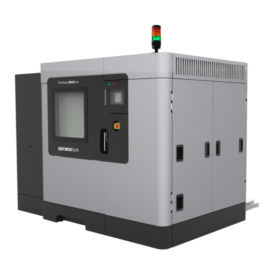
This system incorporates the latest in innovative technologies to provide precision prototypes from a CAD design. Stratasys’ Fused Deposition Modeling (FDM) technology provides prototype parts, including internal features, that can be used to field-test form, fit, and function. The Fortus 900mc features a servo/ballscrew driven XY gantry with multiple high temperature modeling material capability. -
Page 7: Site Prep Tasks
SITE PREP TASKS SELECTING THE SITE Decide where to install the system based on the following: Space Requirements Environmental Requirements Electrical Requirements Compressed Air Requirements LAN Requirements Note: The 900mc system is capable of generating vibrations depending mainly on part build geometry and material characteristics. This consideration will need to be taken into account if locating the system near vibration sensitive equipment. -
Page 8: Minimum Clearances
MINIMUM CLEARANCES Left Side Clearance Minimum 27.16 inches (68.0 cm) Right Side Clearance Minimum 29.47 inches (74.8 cm) Rear Clearance Minimum 29.96 inches (76.1 cm) Front Clearance Minimum 44.42 inches (112.8 cm) Ceiling Height Minimum 115.8 inches (294.1 cm) Please note that the front clearance area must remain clear to provide open access to the emergency stop (which is located on the front surface of the printer). -
Page 9: Environmental Requirements
ENVIRONMENTAL REQUIREMENTS • The Fortus 900mc is for indoor use only. • Operating temperature: 60°F (15.5°C) to 85°F (29°C). Humidity: 20-80% non-condensing. • HEAT OUTPUT Heat output is material dependent due to the various temperatures maintained in the build oven. -
Page 10: Lan Requirements
Forklift truck of sufficient size to raise the system from the shipping skid. • FORKLIFT TRUCK REQUIREMENTS The Fortus 900mc is very heavy and requires a forklift truck with the following minimum capabilities: Ability to lift 6325 lbs. (2875 kg) if the system is uncrated. •... -
Page 11: Moving Crated System
Warning: The system weighs 7247 lbs. (3287 kg) including the crate. Make sure equipment and personnel are capable of moving the system. The Fortus 900mc shipping skid is designed to be moved only from the ends of the shipping skid. Figure 3: Crated System... -
Page 12: Unpacking The System
Caution: Use care when removing the plastic wrap to avoid scratching the system surfaces. Carefully remove the plastic wrap from the system. INSPECT SYSTEM EXTERIOR Inspect the system exterior for dents and scratches. Immediately report any damage to Stratasys and the shipping company. -
Page 13: Remove System From Shipping Skid
LIFTING THE SYSTEM Remove all angle fasteners attaching the Fortus 900mc to the shipping skid. Use a forklift truck to lift the system from the shipping skid. The system can be lifted only from the center forklift channels. Lifting the entire system from either end may result in damage to the system. -
Page 14: Lifting By Crane
LIFTING BY CRANE If lifting by an overhead crane, four spreader bars must be used. Open the right top slide cover. Two spreader bars with a span of 43 in. (86.4 cm) and two with a span of 74 in. (188 cm) must be used to distribute the weight of the system and prevent bending of the lifting assemblies when lifting. -
Page 15: Moving The System
MOVING THE SYSTEM The system can be moved on its casters by using a forklift truck under the end forklift channels. Attach two eye bolts to one end of the system. Make sure to attach nylon straps from the eye bolts on the system to the forklift truck. -
Page 16: Transporting To A New Location
TRANSPORTING TO A NEW LOCATION When transporting the system to a new location, tie downs (front and back) must be used to secure the system. Teflon shields must be used so the panels of the system will not be marred. Figure 7: Tie Down Locations (Front View) Eye Bolts Shipping Tie... -
Page 17: Service Connections
SERVICE CONNECTIONS Caution: A licensed electrician must perform all wiring from service connection to the system - including all connectors, cables, and proper strain relief. Comply with all applicable local and national electric codes. Remove 10 screws that attach the Left Back Access Plate to the system, This provides access to the electrical junction box. - Page 18 Connect the system to the electrical service as follows (Figure 10): Warning: HIGH LEAKAGE CURRENT. Earth connection essential before connecting supply. • Line 1 connects to fuse block L1. • Line 2 connects to fuse block L2. • Line 3 connects to fuse block L3. •...
-
Page 19: Compressed Air Connection
COMPRESSED AIR CONNECTION There are 3 options for coupling the compressed air source: Clamp a 3/8 inch ID hose to the installed female removable fitting (the female has a 3/8 inch hose barb). Remove the female half of the quick disconnect and attach to the male coupling half (i.e., if the installer does not want to use the hose barb). - Page 20 Customers, resellers, and Stratasys employees are encouraged to send comments about our documentation and training to c-support@stratasys.com. We greatly value your comments, review all of them, and use them to improve subsequent releases of the documentation. In your email message please include the document title, part number (located on the front cover), and page number.
Need help?
Do you have a question about the Fortus 900mc and is the answer not in the manual?
Questions and answers