Stratasys Fortus 900mc User Manual
Hide thumbs
Also See for Fortus 900mc:
- Operation and maintenance manual (72 pages) ,
- Site preparation manual (20 pages) ,
- Quick reference card (2 pages)
Table of Contents
Advertisement
Quick Links
Advertisement
Table of Contents

Related Manuals for Stratasys Fortus 900mc


Summary of Contents for Stratasys Fortus 900mc
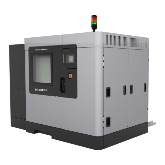
- Page 1 Fortus 900mc ® 3D Production System USER GUIDE Part No. 108314-0011_REV_A...
- Page 2 LIABILITY STATEMENT The information in this document is subject to change without notice. Stratasys, Inc. shall not be liable for errors contained herein or for incidental or consequential damages in connection with the furnishing, performance, or use of this material. Stratasys, Inc. makes no warranty of any kind with regard to this material, including, but not limited to, the implied warranties of merchantability and fitness for a particular purpose.
- Page 3 Welcome to the Fortus 900mc . This systems incorporate the latest in innovative technologies ® that produce accurate and functional parts. Stratasys’ Fused Deposition Modeling (FDM) technology provides prototype parts, including internal features, that can be used to field-test form, fit, and function.
- Page 4 ABOUT THIS GUIDE This guide is your introduction to building parts using a Fortus 3D Production System. It is designed as a learning and reference tool that explains system operation in an easy to understand, step-by-step process. HOW TO USE THIS GUIDE This guide is divided into easy-to-follow chapters.
- Page 5 Added ULTEM 1010 material option, including T14 model tip, information throughout. 108314-0010_REV_A September 2015 Made various minor corrections throughout. August 2016 108314-0011_REV_A Updated document branding per new Stratasys design and guidelines. Added ST130 material information throughout. Added T40 model tip information throughout.
-
Page 6: Table Of Contents
TABLE OF CONTENTS 1 SERVICE AND SUPPORT ..............1 SERVICE AND SOFTWARE SUPPORT ................... 1 In the USA ................................. 1 In Europe ................................1 CONSUMABLE ORDERS......................1 SAFETY INSTRUCTIONS ......................2 Hazard Types ..............................2 Product Safety Signs ............................2 Potential Safety Hazard Areas........................... - Page 7 Materials ................................14 Liquefier Tips ..............................15 OVEN ............................19 Oven Door ............................... 19 Oven Components............................20 CANISTER BAY ........................22 Accessing the Bays ............................22 Canister Bay Components..........................23 SmartSpool System............................24 3 SETUP AND INSTALLATION ............25 GENERAL INFORMATION ...................... 25 Prepare Your Facility for Installation........................
- Page 8 Building Screen ............................... 51 Materials/Tools ..............................52 Calibration Menu ............................. 53 Adjust XYZ Calibration Offsets ........................54 Tips/Materials Change............................. 55 Technician ............................... 56 Administrator ..............................57 System Default ..............................58 Log Off................................59 Queue Window ..............................60 Move Commands ............................61 Powering On the System..........................
- Page 9 6 SYSTEM MAINTENANCE ..............87 UPDATING CONTROLLER SOFTWARE................87 Web Method (preferred method) ........................87 CD Method (alternate method) ........................88 PLACING SYSTEM IN RECEIVE SOFTWARE UPGRADE MODE ........89 REINSTALLING CONTROLLER SOFTWARE (USING USB FLASH DRIVE)......90 MAINTENANCE SCHEDULE....................91 DAILY MAINTENANCE......................
-
Page 10: Service And Support
This chapter provides the user with information on service and support for the Fortus 900mc system. SERVICE AND SOFTWARE SUPPORT If you have a problem with your Fortus 900mc that is not covered in this User Guide, please contact Stratasys Customer Support. -
Page 11: Safety Instructions
The following basic safety tips are given to ensure safe installation, operation, and maintenance of Stratasys equipment and are not to be considered as comprehensive on matters of safety. The Fortus 900mc is designed to be a safe and reliable rapid prototyping printer. Access to areas of the printer are potentially dangerous. -
Page 12: Potential Safety Hazard Areas
Gloves/Sleeves Required: The gloves sign indicates that safety gloves and sleeves approved for high temperatures must be used. These are provided in the Startup Kit. Sharp Object: The sharp object sign indicates the presence of sharp objects. Do not touch sharp objects as they may cause a loss of body parts. Crushed Hand: The crushed hand sign indicates that a crushing hazard exists between two objects. -
Page 13: Guard Door Interlocks
These components are very hot. REMOVING ELECTRICAL POWER Any time service is being performed on the Fortus 900mc AC power must be removed to the system. Perform the system shutdown sequence on the system before removing power to the system. - Page 14 Any time service is being performed on the Fortus 900mc system, especially the electrical panel where high voltage power is present, the incoming power should be locked out to prevent someone else from inadvertently energizing the electrical system. Uninterruptible When line voltage is removed from the system, a UPS ( Power Supply) is designed to provide power to some components in the of the system.
-
Page 15: System Components
2 SYSTEM COMPONENTS This chapter describes the system components of the Fortus 900mc system. Information on model materials and tips that can be used by the system are also included in this chapter. ACCESS DOORS AND PANELS Warning: The access doors should only be removed by an authorized Stratasys service technician. -
Page 16: Top Slide Covers
TOP SLIDE COVERS Allows access to the head, gantry area, and access for changing model and support tips on the head. The cooling fans are located in this area to provide airflow though the upper portion of the system. Warning: Only use an OSHA or CE approved step stool when accessing the area under the top slide covers. -
Page 17: Signal Tower
Signal Tower Power On Power Off Touchscreen Emergency Stop SIGNAL TOWER Visually displays the status of the Fortus 900mc. (Figure 2-3) Green: System is OK; it is building a part, or it is finished building a part. Yellow: All monitored parameters are within tolerance. (See “Health Monitor”... -
Page 18: Back Of System
The computer and the UPS are accessible from the back of the system. Figure 2-4: Fortus 900mc Back View Onboard Computer ONBOARD COMPUTER The onboard computer is the central control unit for the Fortus 900mc. This computer also runs the touchscreen software that provides for the system's user interface. -
Page 19: Ups
The UPS unit is a battery standby system that supplies power (AC voltage) to the computer, oven lights, and head cooling fan in the event of a loss of AC power. It does not power the entire system. You can access the UPS from the back of the system. -
Page 20: System Top
SYSTEM TOP OPENING THE TOP SLIDE COVERS To access the head, the Top Slide Covers need to be opened. The covers share two safety switches and a locking solenoid. The covers remain locked during system operation or when the user moves the gantry or the Z Stage and are unlocked when the system is idle. -
Page 21: Head Assembly
HEAD ASSEMBLY The Head Assembly (Figure 2-7) is designed for use with a wide range of model materials. The board inside the head provides direct heater and thermocouple control. Model and support material are extruded through the head using two liquefiers. Figure 2-7: Head Assembly HEAD MAINTENANCE BRACKET... - Page 22 Figure 2-9: Head Assembly Maintenance Head Assembly Head Maintenance Bracket...
-
Page 23: Model Materials And Tips
MODEL MATERIALS AND TIPS MATERIALS MATERIALS USED The Fortus 900mc system can use a variety of material types: • ABSi model material used with SR-20 soluble support. • ABS-M30 and ABS-M30i model materials used with SR-20 or SR-30 soluble support. SR-30 is ductile and dissolves up to three times faster than SR-20. -
Page 24: Liquefier Tips
Table 2-1: Material Build Temperatures Maximum Maximum Material Extrusion Temp Oven Temp ABSi 330°C (626°F) 85°C (185°F) ABS-M30 320°C (609°F) 95°C (203°F) ABS-M30i ABS-ESD7 320°C (609°F) 95°C (203°F) 330°C (626°F) 100°C (212°F) Nylon 12 355°C (671°F) 120°C (248°F) PC-ABS 330°C (626°F) 110°C (239°F) 365°C (689°F) 145°C (293°F) - Page 25 TIP COMPATIBILITY AND SELECTION Table 2-2 lists the materials available for use with the 900mc and their corresponding tips. Table 2-3 lists the slice heights for each model tip. Table 2-4 provides approximate tip life, based on the amount of material used. •...
- Page 26 Table 2-3: Slice Height Model Tip Slice Height (in) Slice Height (mm) 0.007 0.178 0.010 0.254 0.010 0.254 0.013 0.330 T20B 0.013 0.330 0.020 0.508 Table 2-4: Tip Life Model Tip Life Support Tip Life Support Model Model Material Canisters Canisters ABSi 12620...
- Page 27 Model Tip Life Support Tip Life Support Model Model Material Canisters Canisters PC-ISO 12060 6030 PC-ISO 13570 7540 PC-ISO 13570 7540 ST130 T20B 10553 13570 ULTEM 9085 9010 7540 ULTEM 9085 9010 7540 ULTEM 1010 9010 7540 ULTEM 1010 12062 10560 ULTEM 1010 1500...
- Page 28 TIP IDENTIFICATION Figure 2-10: Tip Identification All unused model and The Soluble support tips are Release support interchangeable - tip is shorter than EXCEPT for Soluble standard tips. Release support tips. Once a tip is used, it is committed to that material type and is no longer interchangeable.
-
Page 29: Oven
OVEN OVEN DOOR The oven door is locked by a solenoid during the building of a part. Pressing the Door button on the Operator Touchscreen will release the solenoid allowing you to open the door. This command is available only while the system is paused or in an idle state. -
Page 30: Oven Components
OVEN COMPONENTS Warning: Oven lights are hot! Do not touch without wearing approved safety gloves. OVEN LAMPS There are two incandescent oven lamps mounted in the two front upper corners of the oven. The 40 watt lamps are rated at 240 volts. There is a lamp (light) switch on the touchscreen, which you can use to manually turn the light ON or OFF. - Page 31 PLATEN The platen is the surface on which parts are built. A plastic build sheet is held to the 36 in. (91.4 cm) X 24 in. (61.0 cm) aluminum platen by the vacuum source. The platen has a waffle pattern system into the top surface. This allows vacuum to pull across the entire surface.
-
Page 32: Canister Bay
PURGE BUCKET The debris chute directs debris into the purge bucket located under the tip cleaning assembly inside the oven chamber. The purge bucket is designed to catch debris from the tip cleaning assembly and collects model and support filament waste. The purge bucket is removable from the system and has a door at the bottom of the basket for waste disposal. -
Page 33: Canister Bay Components
CANISTER BAY COMPONENTS The Fortus 900mc system has four operating material bays - 2 model and 2 support. The upper two bays hold model material; the bottom two bays hold support material. While building, two canisters will be active. An active canister has material filament loaded to the liquefiers (steady green LED). -
Page 34: Smartspool System
SMARTSPOOL SYSTEM The Fortus 900mc uses the SmartSpool system to provide canister information. This allows you to manage material resources, and maximize part build strategies for long, unattended part builds. Each canister contains an ecoded chip (Figure 2-18) that tracks the status of the canister material. Canister information is reported to the system and displayed on the Operator Touchscreen. -
Page 35: Setup And Installation
This chapter describes basic setup and installation of the Fortus 900mc system. GENERAL INFORMATION PREPARE YOUR FACILITY FOR INSTALLATION Follow the Fortus 900mc Site Preparation Guide to ensure that your facility is effectively and safely prepared for system installation. IDENTIFYING YOUR SYSTEM... -
Page 36: Basic Setup
BASIC SETUP MAKING THE NETWORK CONNECTION Processed job files are transferred to the Fortus system through your facility’s Ethernet network. An RJ45 network connector is located on the top right-hand corner at the back of the system. Figure 3-2: Network Connection Air Supply Power Cable RJ45... -
Page 37: Making The Power Cable Connection
(Figure 3-2). High voltage is applied to the system using a Delta connection. The main breaker must be off until a Stratasys authorized Service Technician has verified the connection. This system is only provided with a Delta connection (Figure 3-3). -
Page 38: Setting The Ip Address
SETTING THE IP ADDRESS Power up the system (see “Powering On the System” on page 62). The following Building Screen on the Operator Touchsceen will appear when the Fortus 900mc is powered up. (Figure 3-4): Figure 3-4: Building Screen Material/... - Page 39 Select one of the categories displayed on the Login screen. Figure 3-5: Login Screen After one of the categories is selected, enter the password using the touchscreen keypad and then press OK. From the Building Screen, press the Material/Tools icon and then the Administrator icon and the following screen will appear on the touchscreen.
- Page 40 Figure 3-7: Administrator Screen with Key Pad From the Administrator screen, press the IP address box desired and enter the address using the touchscreen keypad. Press the Network Mask box desired and enter the numbers using the touchscreen keypad. Press the Gateway box desired and enter the numbers using the touchscreen keypad Press the Back icon to exit and return to the Main Menu.
-
Page 41: Operating The System
4 OPERATING THE SYSTEM This chapter explains basic steps in operating the Fortus 900mc system. BASIC USER INTERFACE AND OPERATIONS The Operator Touchscreen is located on the front of the system. Icons are displayed on the screen that are universal and intuitive to use. -
Page 42: Using The Touchscreen
USING THE TOUCHSCREEN The following touchsceen displays the building screen of the Fortus 900mc system (Figure 4-2): Figure 4-2: Building Screen Material Help Back Stop Light Door Login Build Pause Tools Previous Job Selected Job Next Job Queue Window System Log... -
Page 43: Touchscreen Buttons
TOUCHSCREEN BUTTONS The following table displays the button icon and presents a brief description the button function TOUCHSCREEN ICONS Button Description Administration Opens the Administration window. Back Displays the previous window. Build Initiates the building of a part. Calibration XYZ Opens the Calibration XYZ window. - Page 44 Button Description Help Opens the Help menu on the touchscreen. Jobs Previous Job: Causes the last build to be the selected build. Selected Job: Displays the current job being built. Next Job: Causes the next job to be the selected job. Load/Unload Loads or unloads the canister.
- Page 45 Button Description Operator Tools Opens the Operator Tools window. Oven Light Off When pressed, the oven light is turned on. Oven Light On When pressed, the oven light is turned off. Pause Causes the system to temporarily stop building. Press the Build button to restart. Note: Pressing the pause button may be delayed while the current operation completes.
- Page 46 Button Description Tip Wizard Starts the Tip/Material change wizard. Auto Home XYZ.
- Page 47 TOUCHSCREEN SYMBOLS The following symbols are used in the menu displays. Symbol Description Canister Good model canister. The type of material is displayed above the icon and the amount of material remaining in the canister is shown below the icon. The amount is given in cubic inches or cubic centimeters depending on the machine display units.
- Page 48 Symbol Description Model Tip Heating Up Model Tip temperature is heating up. Oven at Setpoint Oven is at setpoint. Oven Cooling Down Oven is cooling down. Oven Heating Up Oven is heating up. Step Complete Step complete. Support Tip Good support tip. This icon is accompanied with an odometer reading displayed at the bottom of the icon.
- Page 49 Symbol Description Support Tip Heating Up Model Tip temperature is heating up. Tip (Flashing) Tip is plugged or failed to load. Tip Past Odometer Tip is past odometer limit. Waiting Waiting for a step to be completed.
-
Page 50: Materials/Tools Display
MATERIALS/TOOLS DISPLAY This window displays the current status of the modeler and support filament, canister status, and tip size and setpoint and the actual temperature of the tips. The color of the tips will turn blue (for model) and brown (for support) when material is fully loaded. -
Page 51: Queue Window
QUEUE WINDOW menu contains files downloaded from the Insight application on your PC workstation. Queue • Job Queue displays current jobs that are waiting in the queue. • A list of stored sample jobs can be displayed by pressing the Sample Queue icon. Note: The jobs listed in either queue can be arranged by pressing any of the categories (i.e., Job Name, Materials, Tips, or Build Time). -
Page 52: Sensor Status
SENSOR STATUS The Sensor Status window displays dynamic information of the status of the system. The following information is displayed. • Temperature of the oven, model and support temperatures along with setpoints • Limit Switch detection • Oven door and top cover slide locks •... -
Page 53: System Status
SYSTEM STATUS The System Status window displays product data, software and network information, along with canister firmware and UPS status. Figure 4-6: System Status SYSTEM DEFAULTS System Defaults can be changed in this window. Units can be displayed in English or metric. User placement can be turned on or off. -
Page 54: System Log
SYSTEM LOG Displays a log of events that have taken place on the system The log list is cleared when the system is powered down or there is a loss of power. Pressing the system log button displays a history of system messages. Pressing the System Log button again clears the current message from the button. -
Page 55: Tip Offset Menu
TIP OFFSET MENU This menu allows the user to adjust the XYZ calibration offsets. The thickness of the support material can also be adjusted. After adjustment, the user can press the Build Calibrations Box to verify the calibration. Figure 4-10: Tip Offset Menu PART PLACEMENT MENU The Part Placement window allows the user to move the part manually to a position on the build sheet. -
Page 56: Administrator Menu
ADMINISTRATOR MENU The Administrator Menu allows an administrator to change the parameters of the system. Software upgrades are accomplished through this window as well as setting system defaults. Figure 4-12: Administrator Menu A keypad is displayed for entering numbers after selecting an IP address, a network mask or gateway number. Figure 4-13: Administrator Menu With Keypad... -
Page 57: System Default Values
SYSTEM DEFAULT VALUES System defaults can be changed from the System Default menu. Figure 4-14: System Default DISPLAY UNITS Select Display Units. • Inches or metric can be selected (factory setting is in English). USER PLACEMENT The part build location can be viewed or changed from the User Placement button. If User Placement is set to Off (default), the part will build in the center of the platen. -
Page 58: Building Screen
BUILDING SCREEN The Building Screen displays the progress of the part being built. Oven temperature is displayed as well as platen vacuum for large and small build sheets. The icon will turn green when vacuum is present. Figure 4-15: Building Screen Build Progress Set Point Temperature Actual Temperature... -
Page 59: Health Monitor
Warning Check Boxes The Health Monitor system determines which of the following four levels of health the Fortus 900mc system is experiencing. At any given time, each value is at one of these health levels. Good – All monitored values are within operational ranges. - Page 60 MONITORED VALUES The following values are monitored by the Health Monitor system: UPS Input Voltage Support Tip Temperature • • UPS Output Voltage Machine state • • UPS Battery Voltage Inner Vacuum (build) • • • Model Tip Plugs • Outer Vacuum (build) •...
-
Page 61: Touchscreen Navigation
TOUCHSCREEN NAVIGATION BUILDING SCREEN “Materials/Tools” on page 52 “Log Off” on page 59 “Health Monitor” on page 49 “Queue Window” on page 41... -
Page 62: Materials/Tools
MATERIALS/TOOLS “Calibration Menu” on page 53 “Tips/Materials Change” on page 55 “Technician” on page 56 “Administrator” on page 57 “Sensor Status” on page 42 “System Status” on page 43... -
Page 63: Calibration Menu
CALIBRATION MENU “Start Auto Tip Calibration” on page 84 “Start Auto Z Zero Calibration” on “Adjust Calibration Offsets” on page 54 “AutoHome XYZ” on... -
Page 64: Adjust Xyz Calibration Offsets
ADJUST XYZ CALIBRATION OFFSETS... -
Page 65: Tips/Materials Change
TIPS/MATERIALS CHANGE Note: Screens may vary depending on tips and materials used. -
Page 66: Technician
TECHNICIAN... -
Page 67: Administrator
ADMINISTRATOR “System Default” on page 58... -
Page 68: System Default
SYSTEM DEFAULT... -
Page 69: Log Off
LOG OFF... -
Page 70: Queue Window
QUEUE WINDOW... -
Page 71: Move Commands
MOVE COMMANDS... -
Page 72: Powering On The System
POWERING ON THE SYSTEM To turn the system ON: Press the flashing green button (Figure 4-1). If there is a completed part in the system, remove the part from the system and install a new build sheet and close the door. Press the Materials/Tools icon from the touchscreen and then press the XYZ icon to auto home the platen. -
Page 73: Basic Job Build Tasks
Nylon 12 parts use a green tinted build sheet. Set the build sheet on the platen. • The Fortus 900mc can accommodate two sizes of build sheets. Make sure the build sheet that is used is centered on the platen. •... -
Page 74: Select A Job To Build
Modify System Defaults: Display units - choose inches or metric. See “Display Units” on page 47 for more information. User Placement on Platen - allows you to choose the part build location. “User Placement” on page 47 for more information. SELECT A JOB TO BUILD From the Building screen, select one of the following job build options: Figure 4-18:... - Page 75 If the User Placement option is set to on, the following screen will appear. Figure 4-19: Positioning a Part Position Part Build Using the touchscreen, position the part on the displayed platen. Press the Build icon to initiate the building of the selected part.
-
Page 76: Build Job Warnings
BUILD JOB WARNINGS If the system detects an issue that may affect a job build, the system displays one of the following warnings: Figure 4-20: Build Job Warnings Head has been changed. Consider tip calibration. • Indicates a new head has been installed. •... - Page 77 Replace Worn Model (or Support) tip. • The system tracks the amount of material extruded through a tip. You will receive this prompt when tip performance may start to become compromised. (Tip-life prediction is an estimated value. Many factors contribute to actual tip-life aside from amount of material extruded. Actual tip-life may differ from predicted tip-life.) •...
-
Page 78: Information Available During A Build
INFORMATION AVAILABLE DURING A BUILD The following information is displayed while building a job: Figure 4-21: Job Information The name of the previous job built. Estimated time to build the job, materials used, tips, and layers. Percentage of job completed. Finished time, elapsed time displayed in hours and minutes, slice and number of layers. -
Page 79: Pausing Or Stopping A Job
PAUSING OR STOPPING A JOB During a part build, the system can be paused: Automatically (canister runs out of material, failure detected, etc.) Note: If an automatic pause occurs, the issue will appear in the System Log Button on the bottom of the screen. Press the Pause icon on the Operator Touchscreen. -
Page 80: After A Job Build
AFTER A JOB BUILD Warning: Wear proper safety equipment when handling items inside the oven. Surfaces in the build chamber can be very hot. The system performs the following actions: The Z Stage is lowered and the head is parked. The touchscreen will displays the following Build Complete message Figure 4-23: Build Complete... -
Page 81: Removing Supports
Ultrasonic or Circulation tank containing a solution of water and WaterWorks soluble solution. For more information on WaterWorks, refer to the WaterWorks User Guide located on Stratasys’ Customer Extranet. SUPPORT MATERIAL FOR PPSF PARTS Removing supports from PPSF parts requires a slightly different support removal process than with ABS, ASA or PC, which uses BASS supports. -
Page 82: Material, Canisters, And Liquefier Tips
The difficulty of support removal is based on the following: part size, amount of supports, support style, and support temperature. Stratasys recommends removing the supports in the following order: Base Structures Thin horizontal sections Around small features Angle support faces... -
Page 83: Removing Canisters
The head drive motors and canister drive motor turn in reverse. The material is pulled back from the head about 4-6 inches (10-15 cm). Note: For some materials (i.e., SR-20), a tip purge is performed before the material is unloaded from the liquefier. The head temperature lowers to standby temperature and the canister LED turns to a slower flashing green (same flash rate as used to indicate canister Ready condition). -
Page 84: Canister Installation
Cut the filament flush with the top of the canister snout. Remove the plastic plug from its storage location (item 6B) and insert it into the filament outlet hole of the canister snout (item 4 and 6A). Pull remaining filament from the drive block and discard all accumulated material in the drive bay. - Page 85 Figure 4-25: Canister Installation Item Description Item Description Foil Tape Plastic Plug (operating position) Anti-Rotation Plug Plastic Plug (storage position) Thumbwheel Door Foam Gasket (operating position) Canister Snout Foam Gasket (storage position) Filament Drop the filament drive block down onto the canister by pulling out the canister drive lever. (Figure 4-26) •...
- Page 86 Figure 4-26: Preloading Filament Filament Present Switch Drive Lever Filament Drive Wheels Filament Thumbwheel Filament Preload filament to the drive wheels: Open the thumbwheel door. Remove the square foam gasket on the inside of the thumbwheel door. (Figure 4-25) Stick the gasket onto the canister. •...
-
Page 87: Loading Material To The Liquefier Tips
LOADING MATERIAL TO THE LIQUEFIER TIPS Note: If you are changing to a different material type or changing tips, follow the procedure outlined in “Changing Tips or Material Type” on page Loading filament to the liquefiers is done in the Idle or Paused mode only, not while building. -
Page 88: Canister Auto Changeover
CANISTER AUTO CHANGEOVER Auto Changeover allows you to leave a long part build unattended. When an active canister becomes empty: The system is paused and the canister drive automatically withdraws residual material from the system. Material is then loaded to the head from the full canister. Note: If the material to be loaded is not the same as the material it is replacing the auto changeover will not occur and the system will enter the mode. -
Page 89: Changing Tips Or Material Type
CHANGING TIPS OR MATERIAL TYPE Note: If you are changing tips, or changing to a different material type, the user interface has a menu selection that guides you through the process. Caution: If the material type is changed, the tips must be changed. Clean the oven and the tip wipe assembly. - Page 90 Open the top slide covers. Place the head in the head maintenance bracket (refer to “Head Maintenance Bracket” on page 12). Warning: Surfaces of the liquefier tips and heater block can be very hot. Loosen the two captive screws that clamp each liquefier tip in place. Remove the tips. Figure 4-29: Liquefier Retaining Screws Liquefier...
-
Page 91: Working With The Job Queues
WORKING WITH THE JOB QUEUES There are two job queues available on the Fortus 900mc - the Job Queue and the Sample Job Queue. Figure 4-31: Job Queues Heading Slide Bar Select either Job Queue or Sample Queue. The Job Queue menu - contains files downloaded from the Insight application on your PC workstation. -
Page 92: System Status
SYSTEM STATUS The System Status screen displays the following information: • System Software Versions • UPS Status Network Setting • Figure 4-32: System Status... -
Page 93: Calibration
5 CALIBRATION This chapter describes basic calibration procedure of the Fortus 900mc system. AUTOMATIC CALIBRATION After tips are changed the user menu will prompt you to perform a series of automatic calibrations: Autocal Tips Calibration, Autohome XYZ, and Auto Z Calibration. -
Page 94: Start Auto Tip Calibration
START AUTO TIP CALIBRATION Start Auto Tip Calibration allows the user to calibrate the tip-to-tip offsets in the Z direction. No operator interaction is required. The system automatically performs this calibration as part of the tip change wizard actions. Proper calibration allows the system to toggle material tips and place the current tip at the precise coordinate necessary to continue accurate part build. - Page 95 Press OK. The screen will pop up asking if you want to apply these values. Press OK. When X and Y are both at 0, proceed to adjusting the Z. If an adjustment entry for either axis is required, re-run the calibration model on a clean build sheet.
-
Page 96: Autohome Xyz
Determine the Z Adjustment. Note: Do not measure for Z adjustment until the Calibration Model shows the XY Offset to be less than 0.002 inch (0.05 mm) for the X and Y axis. Peel the Support layer from the Z Calibration box. Measure the thickness of the Support layer with a caliper or micrometer. -
Page 97: System Maintenance
Open the Control Center application and select the Services tab and then click Check for System Updates. Figure 6-1: Control Center The Stratasys Update Manager window will appear. The application will check to see if the Controller software is current. Follow screen prompts to update the Controller software. -
Page 98: Cd Method (Alternate Method)
This method is for customers who do not have web access. The Controller Software Update CD containing the updated .upg file and must be obtained from Stratasys. Inc. Insert the Controller Software Update CD into the workstation computer and then transfer the .upg file to a known location on the workstation hard drive. -
Page 99: Placing System In Receive Software Upgrade Mode
PLACING SYSTEM IN RECEIVE SOFTWARE UPGRADE MODE Place the system in software upgrade mode by doing the following: Navigate to the Administrator screen and then press the Receive Software Upgrade button. This will allow the system to accept the software upgrade Receive Software Upgrade Upgrade in Process... -
Page 100: Reinstalling Controller Software (Using Usb Flash Drive)
(USING USB FLASH DRIVE) The controller software can be reinstalled using a USB flash drive supplied by Stratasys. All systems ship with a USB flash drive containing the controller software which was current at the time of system manufacture. As such, it is important that controller software be updated as appropriate following software reinstallation using the USB flash drive. -
Page 101: Maintenance Schedule
MAINTENANCE SCHEDULE Maintenance tasks must be performed on a regular basis in order to maintain optimal system operation. Table 6- 1 outlines the general maintenance schedule. Detailed instructions for each task make up the rest of this chapter. Warning: always wear proper heat protective clothing when working inside the oven. -
Page 102: Daily Maintenance
DAILY MAINTENANCE CLEAN THE PLATEN The platen is the surface on which the build sheet is placed for modeling. If debris collects on the platen, it can adversely affect the vacuum which secures the build sheet to the platen. Remove the build sheet from the platen. •... -
Page 103: Empty The Purge Bucket
EMPTY THE PURGE BUCKET The purge bucket is located inside the oven. It catches the material that has been purged or wiped from the liquefiers and liquefier tips. The purge bucket should be emptied daily. (Figure 6-3) Warning: Always wear safety gloves and long sleeves when working inside the oven. -
Page 104: Weekly Maintenance
WEEKLY MAINTENANCE VACUUM THE BUILD ENVELOPE Vacuum the build envelope to remove build material waste, debris, and dust. CLEAN/INSPECT TIP WIPE ASSEMBLY Inspect the Tip Wipe Assembly once a week. Replace parts as necessary when wear is detected. See “Consumable Orders” on page 1 for more information. - Page 105 Figure 6-5: Purge Ledge Assemblies For PPSF and ULTEM Material Only Standard Purge Ledge Inspect the flicker/brush assemblies. The top edge of the flicker should be straight. Replace the flicker if it is notched or bent - a small amount of wear is acceptable (Figure 6-6).
-
Page 106: Quarterly Maintenance
QUARTERLY MAINTENANCE CLEAN THE TIP SENSOR PLUNGER Remove the plunger - gently pull up and out (Figure 6-8). Remove material residue on the top of the plunger with a razor blade. Replace the plunger in the sensor bracket making sure the flat surface is up. Figure 6-8: Tip Sensor Tip Sensor Plunger... -
Page 107: As Needed Maintenance
Avoid streaks by rinsing with clear water and then drying with a soft cloth. In addition to the above noted user maintenance tasks, Stratasys recommends all 900mc systems go through a 1 year PM which addresses lubing and the replacement of wear components and filters, which if not replaced, may contribute to diminished component life. -
Page 108: Troubleshooting
7 TROUBLESHOOTING This chapter describes basic troubleshooting that can be done by the user to correct basic problems with the Fortus 900mc system. GETTING HELP If you have problems with your system or materials, that are not covered in this User Guide or in the Quick... -
Page 109: Finding A Remedy
FINDING A REMEDY Condition Possible Cause Remedy Canister will not load Anti-rotation plug not removed Remove plug. from canister. Rubber thumbwheel insert not Remove thumbwheel insert. removed from thumbwheel door. Empty canister (zero volume). Replace canister. Filament stuck in canister. Remove canister from system and pull out about eight feet (two meters) of material out. - Page 110 Condition Possible Cause Remedy Loss of extrusion Filament stuck in canister. Remove canister from system and pull out (Head will not extrude about 8 feet (2 meters) of material out. material). Ensure filament pulls out freely. Canister drive is too slow. Verify that load time from the canister to the head switch is less than 2 min.
- Page 111 Condition Possible Cause Remedy Material is oozing. Dryer failure. Call Customer Support. Moisture in the canister. Call Customer Support. Air pressure low. Oven not maintaining Heater failure. Call Customer Support. temperatures. Oven door open. Close the oven door; the heater turns off while the door is open.
- Page 112 Customers, resellers, and Stratasys employees are encouraged to send comments about our documentation and training to c-support@stratasys.com. We greatly value your comments, review all of them, and use them to improve subsequent releases of the documentation. In your email message please include the document title, part number (located on the front cover), and page number.
Need help?
Do you have a question about the Fortus 900mc and is the answer not in the manual?
Questions and answers