Lenze g500-B Project Planning Manual
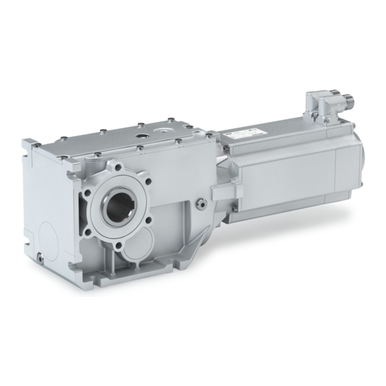
Bevel geared servo motor
Hide thumbs
Also See for g500-B:
- Manual (156 pages) ,
- Project planning (120 pages) ,
- Mounting and switch-on instructions (68 pages)
Table of Contents
Advertisement
Quick Links
Advertisement
Table of Contents

Related Manuals for Lenze g500-B


Summary of Contents for Lenze g500-B
- Page 1 Project planning EN Geared servo motors Bevel geared servo motor g500-B / m850...
-
Page 3: Table Of Contents
Contents Contents About this document Document description Further documents Notations and conventions Product information Product description Identification of the products Features The modular system Information on project planning Safety instructions Basic safety instructions Application as directed Foreseeable misuse Residual hazards Drive dimensioning Final configuration Environmental conditions... - Page 4 Contents Product extensions Torque plates Shaft covers Motor connection Connection via ICN connector Brakes Spring-applied brakes Feedback Resolver Absolute value encoder Temperature monitoring Thermal detectors PT1000 Product codes Motor data Rated data Inverter mains connection 400 V, Self-ventilated Torque characteristics Appendix Good to know Approvals/directives Operating modes of the motor...
-
Page 5: About This Document
Please observe the notes in the following chapters! ▶ Safety instructions ^ 18 ▶ Information on mechanical installation ^ 37 ▶ Information on electrical installation ^ 38 Further documents Information and tools with regard to the Lenze products can be found on the Internet: http://www.lenze.com à Download... -
Page 6: Notations And Conventions
About this document Notations and conventions Notations and conventions This document uses the following conventions to distinguish different types of information: Numeric notation Decimal separator Point The decimal point is always used. Example: 1 234.56 Warning UL warning Are used in English and French. UR warning Text Engineering tools... -
Page 7: Product Information
Synchronous servo motor m850 as basis for geared motor In a power range of 2.0 to 9.2 kW, Lenze offers servo motors with an easily scalable modular design. The drives are designed for the open-loop or closed-loop controlled servo inverter operation. -
Page 8: Identification Of The Products
Product information Identification of the products Identification of the products Gearbox product name Gearbox type Product series Type Rated torque Nm Product g500-B45 g500-B110 g500-B240 g500-B450 Bevel gearbox g500 g500-B600 g500-B820 1500 g500-B1500 2700 g500-B2700 4300 g500-B4300 Product name of the motor Product series Type Flange height... -
Page 9: Features
Product information Features Features Ventilation Temperature monitoring (depending on the mounting position) Oil filler plug (depending on the mounting position) Motor connection Remove oil control plug (depending on the mounting position) Cooling Feedback Spring-applied brake Oil drain plug (depending on the mounting position) Housing type Output shaft... -
Page 10: The Modular System
Product information The modular system The modular system Values printed in bold are standard designs. Values that are not printed in bold are potential extensions, some of them including a surcharge. Geared motors up to 450 Nm Gearboxes g500-B110 g500-B240 g500-B450 Min. - Page 11 Product information The modular system Geared motors from 600 Nm to 4300 Nm Gearboxes g500-B600 g500-B820 g500-B1500 g500-B2700 g500-B4300 Min. motor assignment m850-S120 m850-S120 m850-S120 m850-S120 m850-S120 Max. motor assignment m850-S190 m850-S190 m850-S190 m850-S190 m850-S190 Technical data Max. output torque 1500 2700 4300...
- Page 12 Product information The modular system Models at the output NOTICE Please observe the available gearbox designs! Hollow shaft, with foot Without centring (HBR) With centring (HAR) Flange with through holes (HAK) Hollow shaft with shrink disc, with foot Without centring (SBR) With centring (SAR) Flange with through holes (SAK) Solid shaft, with foot...
- Page 13 Product information The modular system Models at the output Motor connection ICN connector Hybrid connector ICN for one-cable technology Cooling: self-ventilated Feedback Feedback and brake...
- Page 14 Product information The modular system Mounting positions Geared motors In the following graphics, the connector in position 2 is colour-coded. If the mounting position (A … F) changes, the connector positions or terminal box positions (2 … 5) are rotated accordingly. To reduce the number of different versions, the gearboxes can also be ordered with combined mounting positions: g500-B110 ...
- Page 15 Product information The modular system Connector/terminal box The connector or terminal box position (2 ... 5) must be given as a function of the mounting position. Solid shaft Please specify the shaft position 3 or 5 when ordering.
- Page 16 Product information The modular system Shrink disc Please specify the shrink disc position 3 or 5 when ordering. It is not possible to have the flange and the shrink disc in the same position. Flange Please specify the flange position 3 or 5 when ordering.
-
Page 17: Information On Project Planning
With the» Drive Solution Designer« you can carry out the drive dimensioning process quickly and with top quality. The software contains profound and proven expertise with regard to drive applications and mechatronic drive components. Please refer to your competent Lenze sales company. -
Page 18: Safety Instructions
The procedural notes and circuit details described are only proposals. It is up to the user to check whether they can be adapted to the particular applications. Lenze does not take any responsibility for the suitability of the procedures and circuit proposals described. -
Page 19: Residual Hazards
Information on project planning Safety instructions Residual hazards Residual hazards Even if notes given are taken into consideration and protective measures are implemented, the occurrence of residual risks cannot be fully prevented. The user must take the residual hazards mentioned into consideration in the risk assessment for his/her machine/system. - Page 20 Information on project planning Safety instructions Residual hazards Gearbox protection Excessive torques lead to breakage of the gearbox shaft. • Do not exceed the maximum output torques specified in this documentation. Excessive input speeds lead to increased temperatures. • Do not exceed the maximum input speeds specified in this documentation. Lateral forces on the gearbox shaft are possible.
-
Page 21: Drive Dimensioning
The thermal limit speed is to be understood as a recommendation. The mean speed of the drive should not exceed the values specified. If dimensioning processes are complex or reach limit loads, please refer to your Lenze branch office... - Page 22 Information on project planning Drive dimensioning Operation chart S1 operation S2,S3 and S6 operation Check operating conditions Define required input variables Determine correction factor Operating modes and operating time Operating modes and operating time Ambient temperature and installation height Ambient temperature and installation height Mounting position Mounting position Mean speed utilisation...
- Page 23 0.76 0.70 60 °C 0.84 0.78 0.69 0.64 Mounting position Gearbox Mounting position Correction factor g500-H 1.00 0.80 0.80 0.70 1.00 1.00 g500-S 1.00 0.80 0.85 0.70 0.90 0.80 g500-B 1.00 0.80 0.80 0.70 0.80 0.80 4Mounting positions ^ 14...
- Page 24 Information on project planning Drive dimensioning Mean speed utilisation Daily operating time Mean speed utilisation relating to the load speed n 100 % 80 % 60 % 50 % 25 % Correction factor 1.0 h 1.29 1.33 1.38 1.42 1.55 2.0 h 1.15 1.20...
- Page 25 Information on project planning Drive dimensioning Determine gearbox efficiency Gearbox Gearbox efficiency η g500-B 2-stage 0.96 3-stage 0.95 Determination of the required gearbox load capacity Define the required load factor at runtime t Runtime t ≤ 10 % Take the load factor k from diagram into account Runtime t >...
- Page 26 Information on project planning Drive dimensioning Operating mode S1 Calculation of the required drive power Calculation Result Unit Output torque ≥ M / (k Output speed ≥ n Drive power ≥ M / 9549 Check geared servo motor and determine from the selection table Check Selection Unit...
- Page 27 Information on project planning Drive dimensioning Operating modes S2, S3, and S6 Calculation of the required drive power Calculation Result Unit Output torque ≥ M / (k Output speed ≥ (n ) / (k Drive power ≥ M / 9549 Check geared servo motor and determine from the selection table Check Selection...
-
Page 28: Final Configuration
Various surface coatings ensure that the motors operate reliably even at high air humidity, in outdoor installation or in the presence of atmospheric impurities. Any colour from the "RAL Classic" collection can be chosen for the top coat. The OKS-XL (extra Large) version requires a check by your responsible Lenze subsidiary. Surface and corrosion... - Page 29 Information on project planning Final configuration Environmental conditions Lubricants In case of ambient temperatures < -20 °C or > +40 °C, please contact your responsible Lenze sales company The following gearboxes are lubricated for life: g500-B45 • g500-B110 • g500-B240 •...
-
Page 30: Free Spaces
Information on project planning Final configuration Free spaces Free spaces Ventilation For the gearboxes g500-B45 … B240, no ventilation measures are required. The gearbox g500-B240 can optionally be ordered with breather elements. From g500-B450 onwards, the gearboxes are generally outfitted with breather elements. - Page 31 Information on project planning Final configuration Free spaces g500-B240 Mounting position A Mounting position B Mounting position C Filling and ventilation Check Drain...
- Page 32 Information on project planning Final configuration Free spaces Mounting position D Mounting position E Mounting position F Filling and ventilation Check Drain...
- Page 33 Information on project planning Final configuration Free spaces g500-B450 Mounting position A Mounting position B Mounting position C Filling and ventilation Check Drain...
- Page 34 Information on project planning Final configuration Free spaces Mounting position D Mounting position E Mounting position F Filling and ventilation Check Drain...
- Page 35 Information on project planning Final configuration Free spaces g500-B600 ... B4300 Mounting position A Mounting position B Mounting position C Filling and ventilation ③ ① ④ ⑤ ② Check Drain g500-B600 ① g500-B820 ② g500-B1500 ③ g500-B2700 ④ g500-B4300 ⑤...
- Page 36 Information on project planning Final configuration Free spaces Mounting position D Mounting position E Mounting position F Filling and ventilation ④ ⑤ ① ③ ② ③ Check ③ Drain ① ② ④ ⑤ ③ g500-B600 ① g500-B820 ② g500-B1500 ③ g500-B2700 ④...
-
Page 37: Information On Mechanical Installation
4Environmental conditions ^ 28 Ambient media − especially chemically aggressive ones − may damage shaft sealing rings, • lacquers and plastics. If required, contact your responsible Lenze subsidiary. Transport Ensure appropriate handling. • Make sure that all component parts are safely mounted. Secure or remove loose •... -
Page 38: Information On Electrical Installation
The manufacturer of the system or machine is responsible for adherence to the limits • required in connection with EMC legislation. Preparation The notes for the electrical connection can be found in the enclosed mounting instructions. EMC-compliant wiring The EMC-compliant wiring is described in detail in the documentation of the Lenze inverters. -
Page 39: Technical Data
• NOTICE In case of other operating conditions, the achievable values can differ for those mentioned. ▶ In case of extreme operating conditions, please contact your responsible Lenze sales company. Thermal power limit The thermal power limit, defined by the heat balance, limits the permissible permanent gearbox power. -
Page 40: Standards And Operating Conditions
Eurasian conformity: electromagnetic compatibility of technical means Approval cULus UL 1004-1 for USA and Canada (requirements of the CSA 22.2 No.100) UL 1004-6 Servo motor, Lenze file no. E210321 Protection of persons and device protection Enclosure IP54 EN 60034-5 Self-ventilated IP65... -
Page 41: Data Overview
Technical data Data overview Data overview The following tables contain the most important data of the gearbox. The data given for speed, torque and power are valid if the input speed n = 1400 rpm • Application factor c= 1.0 •... - Page 42 Technical data Data overview g500-B240, 2-stage Output speed Max. output Max. drive power Ratio Number of teeth Max. radial force Backlash torque Standard 2,max 1,max rad,max ± 20 % arcmin 5.97 3.565 3030 4.64 4.889 3450 3.85 6.257 2365 3860 4.01 6.883 4070...
- Page 43 Technical data Data overview g500-B450, 3-stage Output speed Max. output Max. drive power Ratio Number of teeth Max. radial force Backlash torque Standard 2,max 1,max rad,max ± 20 % arcmin 8.64 5.002 2401 3760 6.93 6.860 4030 6.10 9.315 3577 4370 5.74 10.328...
- Page 44 Technical data Data overview g500-B600, 3-stage Output speed Max. output Max. drive power Ratio Number of teeth Max. radial force Backlash torque Standard 2,max 1,max rad,max ± 20 % arcmin 11.45 5.067 6293 1242 4600 8.84 6.949 7192 1035 5000 9.36 7.617 15631...
- Page 45 Technical data Data overview g500-B820, 3-stage Output speed Max. output Max. drive power Ratio Number of teeth Max. radial force Backlash torque Standard 2,max 1,max rad,max ± 20 % arcmin 9.71 4.958 9800 8.88 6.800 10200 8.60 7.618 10700 8.32 8.517 11000 8.04...
- Page 46 Technical data Data overview g500-B1500, 3-stage Output speed Max. output Max. drive power Ratio Number of teeth Max. radial force Backlash torque Standard 2,max 1,max rad,max ± 20 % arcmin 18.82 6.866 1792 12000 1006 16.32 9.516 1456 13000 1330 18.83 10.902 36992...
- Page 47 Technical data Data overview g500-B2700, 3-stage Output speed Max. output Max. drive power Ratio Number of teeth Max. radial force Backlash torque Standard 2,max 1,max rad,max ± 20 % arcmin 1328 29.64 6.918 28917 4180 13000 1514 26.58 8.793 41769 4750 14000 2212...
- Page 48 Technical data Data overview g500-B4300, 3-stage Output speed Max. output Max. drive power Ratio Number of teeth Max. radial force Backlash torque Standard 2,max 1,max rad,max ± 20 % arcmin 1054 29.64 5.488 1147 13200 1201 26.58 6.976 29822 4275 14000 1329 22.40...
-
Page 49: Radial Forces And Axial Forces
Technical data Radial forces and axial forces Radial forces and axial forces Permissible radial force The calculation of the permissible radial force must take account of the additional load factor rad, perm rad,max Permissible axial force If there is no radial force, the maximum axial force is 50% of the value in the table F rad,max = 0.5 x F ax, zul... - Page 50 The values were calculated with a load capacity of c= 1.3 and an input speed of 1400 rpm. In case of different operating conditions, considerably higher forces can be transmitted. Please contact Lenze. A hollow shaft with shrink disc (SAR/SBR/SCR/SDR/SAK/SCK) requires a check by Lenze.
-
Page 51: Selection Tables
Technical data Selection tables Selection tables Notes on the selection tables The selection tables represent the available combinations of gearbox, number of stages, ratio and motor for the mounting position A. They only serve as a rough overview. The following legend shows the layout of the selection tables: Example Explanation Inverter mains connection 400 V, self-ventilated... -
Page 52: Inverter Mains Connection 400 V, Self-Ventilated
Technical data Selection tables Inverter mains connection 400 V, Self-ventilated Inverter mains connection 400 V, Self-ventilated 2 kW Inverter operation Geared motor Number of stages g500- m850- 2, max 2, th kgcm² 22.0 67.0 8.244 4.889 B240 S120/S3960 24.0 69.0 7.293 5.185 B110 S120/S3960 27.0 72.0 7.205 5.963... - Page 53 Technical data Selection tables Inverter mains connection 400 V, Self-ventilated Inverter operation Geared motor Number of stages g500- m850- 2, max 2, th kgcm² 7.409 29.745 B820 S120/S3960 6.700 30.522 B240 S120/S3960 6.994 30.985 B450 S120/S3960 95.1 8.099 32.439 B600 S120/S3960 6.652 33.433 B240 S120/S3960...
- Page 54 Technical data Selection tables Inverter mains connection 400 V, Self-ventilated Inverter operation Geared motor Number of stages g500- m850- 2, max 2, th kgcm² 34.7 1500 34.7 7.613 114.166 B1500 S120/S3960 34.6 34.6 6.866 114.364 B820 S120/S3960 34.1 34.1 6.727 116.175 B600 S120/S3960 32.1 28.1...
- Page 55 Technical data Selection tables Inverter mains connection 400 V, Self-ventilated 2.9 kW Inverter operation Geared motor Number of stages g500- m850- 2, max 2, th kgcm² 29.0 88.0 18.672 3.565 B240 S140/S3240 39.0 17.444 4.889 B240 S140/S3240 40.0 20.060 5.002 B450 S140/S3240 51.0 16.851 6.257 B240...
- Page 56 Technical data Selection tables Inverter mains connection 400 V, Self-ventilated Inverter operation Geared motor Number of stages g500- m850- 2, max 2, th kgcm² 99.0 17.877 25.347 B600 S140/S3240 37.870 25.365 B4300 S140/S3240 17.253 25.550 B820 S140/S3240 82.0 18.582 26.061 B600 S140/S3240 87.1 18.777 26.324...
- Page 57 Technical data Selection tables Inverter mains connection 400 V, Self-ventilated Inverter operation Geared motor Number of stages g500- m850- 2, max 2, th kgcm² 41.0 37.0 16.587 78.973 B820 S140/S3240 39.1 1500 39.1 16.367 82.762 B1500 S140/S3240 38.1 1985 38.1 17.623 84.940 B2700 S140/S3240 36.1...
- Page 58 Technical data Selection tables Inverter mains connection 400 V, Self-ventilated 3.1 kW Inverter operation Geared motor Number of stages g500- m850- 2, max 2, th kgcm² 25.0 1111 98.0 15.372 3.565 B240 S120/M3960 34.0 14.144 4.889 B240 S120/M3960 35.0 16.760 5.002 B450 S120/M3960 36.0 69.0 13.193...
- Page 59 Technical data Selection tables Inverter mains connection 400 V, Self-ventilated Inverter operation Geared motor Number of stages g500- m850- 2, max 2, th kgcm² 16.694 29.206 B1500 S120/M3960 13.120 29.744 B600 S120/M3960 13.309 29.745 B820 S120/M3960 12.600 30.522 B240 S120/M3960 12.894 30.985 B450 S120/M3960 85.5...
- Page 60 Technical data Selection tables Inverter mains connection 400 V, Self-ventilated Inverter operation Geared motor Number of stages g500- m850- 2, max 2, th kgcm² 38.5 30.3 12.889 102.790 B820 S120/M3960 35.6 22.4 12.560 111.372 B450 S120/M3960 34.7 1500 34.7 13.513 114.166 B1500 S120/M3960 34.6 31.9...
- Page 61 Technical data Selection tables Inverter mains connection 400 V, Self-ventilated 3.7 kW Inverter operation Geared motor Number of stages g500- m850- 2, max 2, th kgcm² 30.0 1111 21.172 3.565 B240 S120/L3960 42.0 19.944 4.889 B240 S120/L3960 42.0 29.722 4.958 B820 S120/L3960 43.0 22.560 5.002 B450...
- Page 62 Technical data Selection tables Inverter mains connection 400 V, Self-ventilated Inverter operation Geared motor Number of stages g500- m850- 2, max 2, th kgcm² 18.522 23.450 B240 S120/L3960 18.878 25.294 B450 S120/L3960 96.3 20.377 25.347 B600 S120/L3960 1060 40.370 25.365 B4300 S120/L3960 19.753 25.550 B820...
- Page 63 Technical data Selection tables Inverter mains connection 400 V, Self-ventilated Inverter operation Geared motor Number of stages g500- m850- 2, max 2, th kgcm² 52.8 1460 52.8 19.106 74.963 B1500 S120/L3960 51.9 25.0 18.556 76.271 B450 S120/L3960 51.5 1898 51.5 20.809 76.862 B2700 S120/L3960 50.7...
- Page 64 Technical data Selection tables Inverter mains connection 400 V, Self-ventilated 4.8 kW Inverter operation Geared motor Number of stages g500- m850- 2, max 2, th kgcm² 47.0 33.072 3.565 B240 S140/M3240 65.0 31.844 4.889 B240 S140/M3240 66.0 41.622 4.958 B820 S140/M3240 67.0 34.460 5.002 B450 S140/M3240...
- Page 65 Technical data Selection tables Inverter mains connection 400 V, Self-ventilated Inverter operation Geared motor Number of stages g500- m850- 2, max 2, th kgcm² 85.5 30.422 23.450 B240 S140/M3240 30.778 25.294 B450 S140/M3240 78.6 32.277 25.347 B600 S140/M3240 1289 52.270 25.365 B4300 S140/M3240 31.653 25.550...
- Page 66 Technical data Selection tables Inverter mains connection 400 V, Self-ventilated Inverter operation Geared motor Number of stages g500- m850- 2, max 2, th kgcm² 1040 41.4 18.0 30.965 78.182 B600 S140/M3240 1050 41.0 24.1 30.987 78.973 B820 S140/M3240 1101 39.1 1500 39.1 30.767 82.762 B1500...
- Page 67 Technical data Selection tables Inverter mains connection 400 V, Self-ventilated 5 kW Inverter operation Geared motor Number of stages g500- m850- 2, max 2, th kgcm² 75.0 72.322 4.958 B820 S190/S3000 77.0 67.531 5.067 B600 S190/S3000 67.511 6.800 B820 S190/S3000 64.963 6.949 B600 S190/S3000 70.272 7.618...
- Page 68 Technical data Selection tables Inverter mains connection 400 V, Self-ventilated Inverter operation Geared motor Number of stages g500- m850- 2, max 2, th kgcm² 92.9 60.6 63.043 32.291 B820 S190/S3000 92.5 58.7 62.399 32.439 B600 S190/S3000 92.2 1500 92.2 64.063 32.547 B1500 S190/S3000 91.3 2217...
- Page 69 Technical data Selection tables Inverter mains connection 400 V, Self-ventilated Inverter operation Geared motor Number of stages g500- m850- 2, max 2, th kgcm² 1619 28.2 4300 28.2 65.760 106.517 B4300 S190/S3000 1627 28.0 2700 25.3 65.242 107.056 B2700 S190/S3000 1735 26.3 1500 24.2 61.913...
- Page 70 Technical data Selection tables Inverter mains connection 400 V, Self-ventilated 5.9 kW Inverter operation Geared motor Number of stages g500- m850- 2, max 2, th kgcm² 82.0 56.122 4.958 B820 S140/L3240 83.0 48.960 5.002 B450 S140/L3240 84.0 51.331 5.067 B600 S140/L3240 51.311 6.800 B820 S140/L3240 47.082...
- Page 71 Technical data Selection tables Inverter mains connection 400 V, Self-ventilated Inverter operation Geared motor Number of stages g500- m850- 2, max 2, th kgcm² 1858 96.8 60.213 24.456 B2700 S140/L3240 96.8 45.278 25.294 B450 S140/L3240 70.8 46.777 25.347 B600 S140/L3240 1778 66.770 25.365 B4300 S140/L3240...
- Page 72 Technical data Selection tables Inverter mains connection 400 V, Self-ventilated Inverter operation Geared motor Number of stages g500- m850- 2, max 2, th kgcm² 1183 45.3 1500 33.3 46.918 71.566 B1500 S140/L3240 1189 45.0 2700 35.7 51.866 71.951 B2700 S140/L3240 1189 45.0 4300 39.2 52.853...
- Page 73 Technical data Selection tables Inverter mains connection 400 V, Self-ventilated 7.5 kW Inverter operation Geared motor Number of stages g500- m850- 2, max 2, th kgcm² 128.622 4.958 B820 S190/M3000 123.831 5.067 B600 S190/M3000 123.811 6.800 B820 S190/M3000 139.052 6.866 B1500 S190/M3000 121.263 6.949 B600 S190/M3000...
- Page 74 Technical data Selection tables Inverter mains connection 400 V, Self-ventilated Inverter operation Geared motor Number of stages g500- m850- 2, max 2, th kgcm² 78.9 117.820 29.744 B600 S190/M3000 118.009 29.745 B820 S190/M3000 96.5 2466 88.0 132.989 31.097 B4300 S190/M3000 92.9 46.9 119.343 32.291 B820...
- Page 75 Technical data Selection tables Inverter mains connection 400 V, Self-ventilated Inverter operation Geared motor Number of stages g500- m850- 2, max 2, th kgcm² 2698 25.4 4300 25.4 118.213 118.336 B4300 S190/M3000 2698 25.3 2700 22.1 118.213 118.370 B2700 S190/M3000 2861 23.9 1500 13.3 118.213...
- Page 76 Technical data Selection tables Inverter mains connection 400 V, Self-ventilated 9.2 kW Inverter operation Geared motor Number of stages g500- m850- 2, max 2, th kgcm² 204.022 4.958 B820 S190/L2520 199.231 5.067 B600 S190/L2520 199.211 6.800 B820 S190/L2520 214.452 6.866 B1500 S190/L2520 196.663 6.949 B600 S190/L2520...
- Page 77 Technical data Selection tables Inverter mains connection 400 V, Self-ventilated Inverter operation Geared motor Number of stages g500- m850- 2, max 2, th kgcm² 96.7 32.6 195.382 26.061 B600 S190/L2520 95.7 43.7 195.577 26.324 B820 S190/L2520 95.6 1500 55.1 202.593 26.353 B1500 S190/L2520 94.0 2672...
-
Page 78: Dimensions
If the mounting area (foot support) towards the motor is longer than the gearbox foot, some motors collide with the mounting area! For an accurate check of the geometrical data, Lenze recommends the use of the »Product Finder« at www.Lenze.com. - Page 79 Technical data Dimensions Basic dimensions g500-B110 Gearbox design: hollow shaft, with foot (HAR/HBR/HAK) Motor m850- S120/S3960 S120/M3960 Total length Motor length Length of motor options Δ L Motor diameter Motor/connection distance...
- Page 80 Technical data Dimensions Basic dimensions g500-B110 Gearbox design: hollow shaft with shrink disc, with foot (SAR/SBR/SAK) Motor m850- S120/S3960 S120/M3960 Total length Motor length Length of motor options Δ L Motor diameter Motor/connection distance...
- Page 81 Technical data Dimensions Basic dimensions g500-B110 Gearbox design: solid shaft, with foot (VAR/VBR/VAK) Motor m850- S120/S3960 S120/M3960 Total length Motor length Length of motor options Δ L Motor diameter Motor/connection distance...
- Page 82 Technical data Dimensions Basic dimensions g500-B240 Gearbox design: hollow shaft, with foot (HAR/HBR/HAK) Motor m850- S120/S3960 S120/M3960 S120/L3960 S140/S3240 S140/M3240 Total length Motor length Length of motor options Δ L Motor diameter Motor/connection distance...
- Page 83 Technical data Dimensions Basic dimensions g500-B240 Gearbox design: hollow shaft with shrink disc, with foot (SAR/SBR/SAK) Motor m850- S120/S3960 S120/M3960 S120/L3960 S140/S3240 S140/M3240 Total length Motor length Length of motor options Δ L Motor diameter Motor/connection distance...
- Page 84 Technical data Dimensions Basic dimensions g500-B240 Gearbox design: solid shaft, with foot (VAR/VBR/VAK) Motor m850- S120/S3960 S120/M3960 S120/L3960 S140/S3240 S140/M3240 Total length Motor length Length of motor options Δ L Motor diameter Motor/connection distance...
- Page 85 Technical data Dimensions Basic dimensions g500-B450 Gearbox design: hollow shaft, with foot (HAR/HBR/HAK) Motor m850- S120/S3960 S120/M3960 S120/L3960 S140/S3240 S140/M3240 S140/L3240 Total length Motor length Length of motor options Δ L Motor diameter Motor/connection distance...
- Page 86 Technical data Dimensions Basic dimensions g500-B450 Gearbox design: hollow shaft with shrink disc, with foot (SAR/SBR/SAK) Motor m850- S120/S3960 S120/M3960 S120/L3960 S140/S3240 S140/M3240 S140/L3240 Total length Motor length Length of motor options Δ L Motor diameter Motor/connection distance...
- Page 87 Technical data Dimensions Basic dimensions g500-B450 Gearbox design: solid shaft, with foot (VAR/VBR/VAK) Motor m850- S120/S3960 S120/M3960 S120/L3960 S140/S3240 S140/M3240 S140/L3240 Total length Motor length Length of motor options Δ L Motor diameter Motor/connection distance...
- Page 88 Technical data Dimensions Basic dimensions g500-B600 Gearbox design: hollow shaft, with foot (HAR/HBR/HAK) Motor m850- S120/ S120/ S120/ S140/ S140/ S140/ S190/ S190/ S190/ S3960 M3960 L3960 S3240 M3240 L3240 S3000 M3000 L2520 Total length Motor length Length of motor options Δ...
- Page 89 Technical data Dimensions Basic dimensions g500-B600 Gearbox design: hollow shaft with shrink disc, with foot (SAR/SBR/SAK) Motor m850- S120/ S120/ S120/ S140/ S140/ S140/ S190/ S190/ S190/ S3960 M3960 L3960 S3240 M3240 L3240 S3000 M3000 L2520 Total length Motor length Length of motor options Δ...
- Page 90 Technical data Dimensions Basic dimensions g500-B600 Gearbox design: solid shaft, with foot (VAR/VBR/VAK) Motor m850- S120/ S120/ S120/ S140/ S140/ S140/ S190/ S190/ S190/ S3960 M3960 L3960 S3240 M3240 L3240 S3000 M3000 L2520 Total length Motor length Length of motor options Δ...
- Page 91 Technical data Dimensions Basic dimensions g500-B820 Gearbox design: hollow shaft, with foot (HAR/HBR/HAK) Motor m850- S120/ S120/ S120/ S140/ S140/ S140/ S190/ S190/ S190/ S3960 M3960 L3960 S3240 M3240 L3240 S3000 M3000 L2520 Total length Motor length Length of motor options Δ...
- Page 92 Technical data Dimensions Basic dimensions g500-B820 Gearbox design: hollow shaft with shrink disc, with foot (SAR/SBR/SAK) Motor m850- S120/ S120/ S120/ S140/ S140/ S140/ S190/ S190/ S190/ S3960 M3960 L3960 S3240 M3240 L3240 S3000 M3000 L2520 Total length Motor length Length of motor options Δ...
- Page 93 Technical data Dimensions Basic dimensions g500-B820 Gearbox design: solid shaft, with foot (VAR/VBR/VAK) Motor m850- S120/ S120/ S120/ S140/ S140/ S140/ S190/ S190/ S190/ S3960 M3960 L3960 S3240 M3240 L3240 S3000 M3000 L2520 Total length Motor length Length of motor options Δ...
- Page 94 Technical data Dimensions Basic dimensions g500-B1500 Gearbox design: hollow shaft, with foot (HAR/HBR/HAK) Motor m850- S120/ S120/ S120/ S140/ S140/ S140/ S190/ S190/ S190/ S3960 M3960 L3960 S3240 M3240 L3240 S3000 M3000 L2520 Total length Motor length Length of motor options Δ...
- Page 95 Technical data Dimensions Basic dimensions g500-B1500 Gearbox design: hollow shaft with shrink disc, with foot (SAR/SBR/SAK) Motor m850- S120/ S120/ S120/ S140/ S140/ S140/ S190/ S190/ S190/ S3960 M3960 L3960 S3240 M3240 L3240 S3000 M3000 L2520 Total length Motor length Length of motor options Δ...
- Page 96 Technical data Dimensions Basic dimensions g500-B1500 Gearbox design: solid shaft, with foot (VAR/VBR/VAK) Motor m850- S120/ S120/ S120/ S140/ S140/ S140/ S190/ S190/ S190/ S3960 M3960 L3960 S3240 M3240 L3240 S3000 M3000 L2520 Total length Motor length Length of motor options Δ...
- Page 97 Technical data Dimensions Basic dimensions g500-B2700 Gearbox design: hollow shaft, with foot (HAR/HBR/HAK) Motor m850- S120/ S120/ S120/ S140/ S140/ S140/ S190/ S190/ S190/ S3960 M3960 L3960 S3240 M3240 L3240 S3000 M3000 L2520 Total length Motor length Length of motor options Δ...
- Page 98 Technical data Dimensions Basic dimensions g500-B2700 Gearbox design: hollow shaft with shrink disc, with foot (SAR/SBR/SAK) Motor m850- S120/ S120/ S120/ S140/ S140/ S140/ S190/ S190/ S190/ S3960 M3960 L3960 S3240 M3240 L3240 S3000 M3000 L2520 Total length Motor length Length of motor options Δ...
- Page 99 Technical data Dimensions Basic dimensions g500-B2700 Gearbox design: solid shaft, with foot (VAR/VBR/VAK) Motor m850- S120/ S120/ S120/ S140/ S140/ S140/ S190/ S190/ S190/ S3960 M3960 L3960 S3240 M3240 L3240 S3000 M3000 L2520 Total length Motor length Length of motor options Δ...
- Page 100 Technical data Dimensions Basic dimensions g500-B4300 Gearbox design: hollow shaft, with foot (HAR/HBR/HAK) Motor m850- S120/ S120/ S120/ S140/ S140/ S140/ S190/ S190/ S190/ S3960 M3960 L3960 S3240 M3240 L3240 S3000 M3000 L2520 Total length Motor length Length of motor options Δ...
- Page 101 Technical data Dimensions Basic dimensions g500-B4300 Gearbox design: hollow shaft with shrink disc, with foot (SAR/SBR/SAK) Motor m850- S120/ S120/ S120/ S140/ S140/ S140/ S190/ S190/ S190/ S3960 M3960 L3960 S3240 M3240 L3240 S3000 M3000 L2520 Total length Motor length Length of motor options Δ...
- Page 102 Technical data Dimensions Basic dimensions g500-B4300 Gearbox design: solid shaft, with foot (VAR/VBR/VAK) Motor m850- S120/ S120/ S120/ S140/ S140/ S140/ S190/ S190/ S190/ S3960 M3960 L3960 S3240 M3240 L3240 S3000 M3000 L2520 Total length Motor length Length of motor options Δ...
-
Page 103: Weights
Technical data Weights Additional weights Weights Basic weights Weights with oil filling for mounting position A, all values are approximate weights must be observed! 4Additional ^ 103 2-stage gearbox Geared motor m850- S120/S3960 S120/M3960 S120/L3960 S140/S3240 S140/M3240 g500-B110 11,2 14,0 g500-B240 15,5 18,3... -
Page 104: Product Extensions
Product extensions Product extensions Torque plates The torque support is usually effected by means of the foot or flange. The torque plates that can be fitted are another possibility. In this case, the torque support is provided only via one point and is suitable for shaft-mounted gearboxes, among other things. - Page 105 Product extensions Torque plates Torque plate on threaded pitch circle g500-B45 ...B110 Gearbox Dimensions Mass g500-B45 12.0 20.0 42.0 g500-B110 13.0 10.0 25.0 54.0 11.0...
- Page 106 Product extensions Torque plates g500-B820 ... B1500 Gearbox Dimensions Mass g500-B820 38.0 28.0 31.5 40.0 20.0 50.0 20.5 g500-B1500 44.0 32.0 36.0 46.0 25.0 65.0 24.0...
- Page 107 Product extensions Torque plates Torque plate at housing foot g500-B240 g500-B450 Gearbox Mass g500-B240 g500-B450...
- Page 108 Product extensions Torque plates g500-B600 ... B4300 Gearbox Dimensions Mass g500-B600 16.4 40.0 55.0 60.0 18.0 g500-B820 16.4 45.0 55.0 60.0 25.0 g500-B1500 16.4 52.5 55.0 60.0 25.0 g500-B2700 25.0 60.0 72.0 80.0 30.0 10.0 g500-B4300 25.0 70.0 92.0 40.0 13.0...
-
Page 109: Shaft Covers
Product extensions Shaft covers Shaft covers The hoseproof hollow shaft cover protects the hollow shaft from objects falling in. It is sealed by a flat gasket between cover and housing. Thus, the hollow shaft is protected from dust and water jets. The cover is loosely enclosed and can be mounted on both sides of the hollow shaft bore. - Page 110 Product extensions Shaft covers Hoseproof hollow shaft cover g500-B45 ..B4300 Product Dimensions Mass g500-B45 55.0 g500-B110 65.0 g500-B240 75.0 g500-B450 79.5 g500-B600 90.0 g500-B820 97.0 g500-B1500 g500-B2700 g500-B4300...
- Page 111 Product extensions Shaft covers Shrink disc cover g500-B45 ... B4300 Product Dimensions Mass g500-B45 65.0 87.5 g500-B110 79.0 97.5 g500-B240 90.0 g500-B450 90.0 g500-B600 g500-B820 g500-B1500 g500-B2700 g500-B4300...
-
Page 112: Motor Connection
The connection takes place via a Lenze hybrid system cable. The advantage: all the required wiring takes place in just one plug. In order to provide for a quick and error-free connection of Lenze motors to Lenze inverters, we recommend using prefabricated Lenze system cables. In this way, proper functioning and the compliance with statutory provisions such as EMC, UL, etc. - Page 113 Product extensions Motor connection Connection via ICN connector Power and brake connection Connector ICN-M23 for motor: m850-S120/S3960 m850-S140/S3240 m850-S190/S3000 m850-S120/M3960 m850-S140/M3240 m850-S120/L3960 ICN-M23 connector assignment 6-pole Contact Name Meaning Holding brake + Holding brake - PE conductor Power phase U Power phase V Power phase W NOTICE...
- Page 114 Product extensions Motor connection Connection via ICN connector Feedback and temperature monitoring connection ICN-M23 connector assignment Resolver Contact Name Meaning +Ref Code 0° Transformer windings -Ref +VCC ETS Power supply: electronic nameplate +COS Stator windings cosine -COS +SIN Stator windings Sine -SIN Not assigned Shield...
- Page 115 Product extensions Motor connection Connection via ICN connector Motor plug connection assignment NOTICE When making your selection, the motor data and permissible currents of the cables according to the system cable system manual must be observed. Power terminal connectors Motor code m850- S120/S3960 S120/M3960...
- Page 116 Product extensions Motor connection Connection via ICN connector Hybrid cables for one-cable technology Motor code m850- S120/S3960 S140/S3240 S190/M3000 S120/M3960 S140/M3240 S120/L3960 Connector with bayonet catch ICN-M23 hybrid Order code for hybrid cable 1.5 mm Cable length 2.0 m EYP0080A0020M11A00 Cable length 3.5 m EYP0080A0035M11A00 Cable length 5.0 m...
-
Page 117: Brakes
If long motor supply cables are used, pay attention to the ohmic voltage drop along the cable and compensate for it with a higher voltage at the input end of the cable. The following applies to Lenze system cables: Resulting supply voltage U[V] U [V] 0.08... - Page 118 Product extensions Brakes NOTICE In case of travel axes, the compliance of the permissible ratio of mass inertia load/brake motor (J ) ensures that the permissible maximum switching energy of the brake will not be exceeded and at least the values given for the emergency stop functions from the given speed (see rated data) are applied.
-
Page 119: Spring-Applied Brakes
Product extensions Brakes Spring-applied brakes Spring-applied brakes Rated data NOTICE Engagement and disengagement times apply to rated voltage (± 0 %) and suppressor circuit of the brakes with a varistor with DC switching. Without a suppressor circuit, the times may be longer. - Page 120 Product extensions Brakes Spring-applied brakes Motor m850-S190/S3000 m850-S190/M3000 m850-S190/L2520 Supply voltage range 21.6 ... 25.2 in,DC Rated voltage rated,DC Rated torque At 20 °C rated At 120 °C rated Output current rated Engagement time Disengagement time Maximum switching energy 5700 Mass 6.70 Moment of inertia...
-
Page 121: Feedback
Servo motors can perform speed-dependent safety functions for safe speed and / or safe relative position monitoring in a drive system by Lenze inverters or Controllers. In case of inverters, these functions are implemented by integrable safety modules and in case of Controllers by the additionally required Safety Controller. -
Page 122: Resolver
Product extensions Feedback Resolver Resolver The stator-supplied, 2-pole resolver with two stator windings shifted by 90 degrees and a rotor winding with a transformer winding can record both the speed and the rotor position, just like a single-turn absolute value encoder. The rotor position can be determined within one mechanical motor revolution after a voltage failure. -
Page 123: Absolute Value Encoder
Product extensions Feedback Absolute value encoder Absolute value encoder Absolute value encoders can detect the speed, the rotor position, and the machine position with a very high resolution. They are used for the positioning of dynamic applications and do not require homing. The digital absolute value encoder AM20-8V-D for one-cable technology is possible with the following motors: m850-S120/S3960... -
Page 124: Temperature Monitoring
Product extensions Temperature monitoring Thermal detectors PT1000 Temperature monitoring Thermal detectors PT1000 The thermal sensors used continuously monitor the motor temperature. The temperature information is transferred to the inverter using the system cable of the feedback system. This is not a full motor protection! The motors are monitored via three thermal sensors connected in series (1x PT1000 + 2x PTC 150 °C ). -
Page 125: Product Codes
Product codes Product codes Gearbox product code Example Product type Gearboxes Product family Generation Gearbox type Bevel gearbox Output torque 45 Nm 110 Nm 240 Nm 450 Nm 600 Nm 820 Nm 1500 Nm 2700 Nm 4300 Nm 8000 Nm 13000 Nm 20000 Nm Type of construction... - Page 126 32 x 100 rpm 40 x 100 rpm Degree of protection IP5x IP6x Cooling No cooling Brake attachment No brake Spring-applied brake Permanent magnet brake Encoder mounting Resolver Absolute value encoder Digital absolute value encoder Product approval CE; cULus Manufacturer Lenze Internal key...
-
Page 127: Motor Data
Motor data Motor data Rated data Inverter mains connection 400 V, Self-ventilated Product name m850-S120/S3960 m850-S120/M3960 m850-S120/L3960 Standstill torque 6.50 11.0 15.0 Rated torque 4.80 7.40 9.00 Max. torque 14.5 29.0 44.0 Max. Rated speed 3960 3960 3960 Rated power 2.00 3.10 3.70 Standstill current... - Page 128 Motor data Rated data Inverter mains connection 400 V, Self-ventilated Product name m850-S190/S3000 m850-S190/M3000 m850-S190/L2520 Standstill torque 27.0 46.0 67.0 Rated torque 16.0 24.0 35.0 Max. torque 71.0 Max. Rated speed 3000 3000 2520 Rated power 5.00 7.50 9.20 Standstill current 16.0 26.8 30.8...
-
Page 129: Torque Characteristics
Torque characteristics Torque characteristics m-n characteristics for your motor-inverter combination can be found on the Internet: http://www.lenze.com à Product Finder à M-n characteristics The data apply to an inverter mains voltage of 3 x 400 V. m850-S120/S3960 = 4 V... - Page 130 Motor data Torque characteristics m850-S120/L3960 = 4 V = 36 V = 3x I = 2x I 500 1000 1500 2000 2500 3000 3500 4000 4500 5000 5500 6000 r/min m850-S140/S3240 = 4 V = 36 V = 2x I 1000 1500 2000...
- Page 131 Motor data Torque characteristics m850-S140/M3240 = 4 V = 36 V = 3x I = 2x I 1000 1500 2000 2500 3000 3500 4000 4500 5000 r/min m850-S140/L3240 = 4 V = 36 V = 3x I = 2x I 1000 1500 2000...
- Page 132 Motor data Torque characteristics m850-S190/S3000 = 4 V = 36 V = 3x I = 2x I 1000 1500 2000 2500 3000 3500 4000 r/min m850-S190/M3000 = 4 V = 36 V = 3x I = 2x I 1000 1500 2000 2500 3000...
- Page 133 Motor data Torque characteristics m850-S190/L2520 = 4 V = 36 V = 3x I = 2x I 1000 1500 2000 2500 3000 3500 4000 r/min...
-
Page 134: Appendix
Appendix Approvals/directives Appendix Good to know Approvals/directives China Compulsory Certification documents the compliance with the legal product safety requirements of the PR of China - in accordance with Guobiao standards. CSA certificate, tested according to US and Canada standards Union Européenne documents the declaration of the manufacturer that EU Directives are complied with. -
Page 135: Operating Modes Of The Motor
Appendix Good to know Operating modes of the motor Operating modes of the motor Operating modes S1 ... S10 as specified by EN 60034-1 describe the basic stress of an electrical machine. In continuous operation a motor reaches its permissible temperature limit if it outputs the rated power dimensioned for continuous operation. -
Page 136: Enclosures
Appendix Good to know Enclosures Enclosures The degree of protection indicates the suitability of a motor for specific ambient conditions with regard to humidity as well as the protection against contact and the ingress of foreign particles. The degrees of protection are classified by EN 60529. The first code number after the code letters IP indicates the protection against the ingress of foreign particles and dust. - Page 140 © 05/2019 | | 1.0 Ö Lenze Drives GmbH Postfach 10 13 52, D-31763 Hameln Breslauer Straße 3, D-32699 Extertal Germany HR Lemgo B 6478 +49 5154 82-0 Ü Ø +49 5154 82-2800 sales.de@lenze.com Ù www.lenze.com Ú...
Need help?
Do you have a question about the g500-B and is the answer not in the manual?
Questions and answers