Advertisement
Quick Links
Thank you for purchasing a Sealey product. Manufactured to a high standard, this product will, if used according to these instructions,
and properly maintained, give you years of trouble free performance.
IMPORTANT: PLEASE READ THESE INSTRUCTIONS CAREFULLY. NOTE THE SAFE OPERATIONAL REQUIREMENTS, WARNINGS & CAUTIONS. USE
THE PRODUCT CORRECTLY AND WITH CARE FOR THE PURPOSE FOR WHICH IT IS INTENDED. FAILURE TO DO SO MAY CAUSE DAMAGE AND/OR
PERSONAL INJURY AND WILL INVALIDATE THE WARRANTY. KEEP THESE INSTRUCTIONS SAFE FOR FUTURE USE.
Refer to
instruction
manual
1. SAFETY
If you are in any doubt about electrical safety consult a qualified electrician.
9
Only for use with 12 - 42 volt DC systems.
9
DO NOT apply voltage or current to the probe that exceeds the specified maximum of 42V DC.
8
DO NOT use with industrial 110V systems.
8
DO NOT use on any circuit directly or indirectly connected to AC lines or any other AC power source.
8
DO NOT use with any component or circuits of the ignition system.
8
Before using this device, check the vehicle's electrical wiring and disconnect any part or system sensitive to voltage and current pulses
9
such as air bags, electronic control modules, etc.
Always check the instructions and procedures indicated in the vehicle service manual before attempting to disconnect any part or
9
subsystem of the electrical circuit.
When not in use, store the probe carefully in a safe, dry, childproof location. Avoid extremes of temperature.
9
DO NOT use the unit around explosive gases, vapour or dust. When the power switch is operated (forwards or backwards), battery
8
current is conducted to the tip of the probe which may cause sparks when contacting earth or other certain circuits.
DO NOT use leads if damaged or if the wire is bared in any way.
8
DO NOT use this tester for any purpose other than that for which it has been designed.
8
2.
INTRODUCTION
i
A range of functions allow automotive electricians and mechanics the ability to effectively diagnose short circuits and bad earths. The
4.6mtr lead connects to a 12V battery supply and reaches to all areas of the vehicle. Fly lead allows continuity and polarity testing with
a high-contrast LCD display with 9mm high (3V to 42V) read-out. Activate components in situ or prior to installation. Features audible
and positive/negative voltage indicator plus two integral work lights. Kit includes three probe extension leads, two wire piercing probes,
two lead adaptors and a crocodile clip. Supplied in a carry-case.
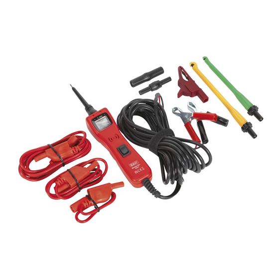
3. CONTENTS
fig.1
3.1.
Polarity Indicator and Audio Tone.
3.1.1.
The "RED/GREEN Polarity Indicator" lights up when the probe tip voltage matches the battery voltage within ± 0.5 volts. This means
that if you contact a circuit that is not a good earth or a good positive, you will not see the "RED/GREEN Polarity Indicator" lighting.
3.1.2.
The Audio Tone runs parallel to the "RED/GREEN Polarity Indicator, and will also NOT react when contacting a circuit that does not
match the battery voltage within ± 0.5 volts.
© Jack Sealey Limited
AUTO PROBE WITH LCD DISPLAY 3V - 42V
PP7
MODEL NO:
8
9
1
2
(-)
(+)
Auxiliary earth
5
4
Original Language Version
1) Probe body.
2) Probe tip.
3) Wire piercing probe (green).
6
4) Wire piercing probe (yellow).
5) 300mm flexi-lead.
6) 900mm flexi-lead.
7) 1800mm flexi-lead.
8) Male/male adaptor.
9) Female/female adaptor.
10) Crocodile clip (female adaptor).
10
3
7
PP7
Issue:4 (4) 17/09/18
Advertisement

Related Manuals for Sealey PP7


Summary of Contents for Sealey PP7
- Page 1 AUTO PROBE WITH LCD DISPLAY 3V - 42V MODEL NO: Thank you for purchasing a Sealey product. Manufactured to a high standard, this product will, if used according to these instructions, and properly maintained, give you years of trouble free performance.
- Page 2 Contact the probe tip to a POSITIVE circuit. The red positive sign, (+) LED will light and the voltmeter will display the voltage. 4.3.2. A high-pitched tone will sound. 4.3.3. While the PP7 is in “Power Mode”, contact the probe tip to a NEGATIVE circuit. The green negative sign, (-) LED will light and the voltmeter will display the voltage. 4.4. Continuity Testing. See fig.3.
- Page 3 Note: It is our policy to continually improve products and as such we reserve the right to alter data, specifications and component parts without prior notice. Important: No Liability is accepted for incorrect use of this product. Warranty: Guarantee is 12 months from purchase date, proof of which is required for any claim. Sealey Group, Kempson Way, Suffolk Business Park, Bury St Edmunds, Suffolk. IP32 7AR 01284 757500 01284 703534 sales@sealey.co.uk www.sealey.co.uk...