Advertisement
Quick Links
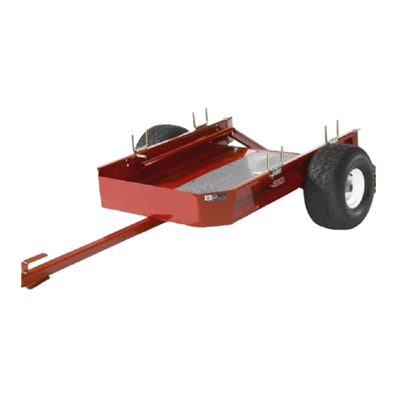
Rail Ramp Conversion Kit
For Trans Pro 100
Model No. 04246
1. Secure tube assembly mounting brackets to square
holes in each side of trailer with (4) carriage bolts, flat
washers and locknuts (Fig. 1). Position tube assemblies
so small cross tubes are to the rear.
Note: On trailers with serial numbers prior to 220000001,
all tube assembly mounting holes are not in sides of trailer
and will have to mounted as follows:
Secure upper rear hole in tube assembly mounting
bracket to top rear square hole in side of trailer.
Position tube assembly so it is parallel to top of trailer.
1
1. Tube assembly
2. Cross tube
3. Position a locking bracket onto each side of ramp so
they align with underside of load ramps, engage with
coated pins in load ramps and aligns with holes in
ramp (Fig. 1 & 3). Only one set of mounting holes is
used per locking bracket.
2003 by The Toro Company
8111 Lyndale Avenue South
Bloomington, MN 55420-1196
2
7
Figure 1
3. Locking bracket
4. Load ramp
Installation Instructions
Using tube assembly mounting brackets as templates,
locate, mark and drill (3) .390" dia. holes in side of
trailer.
Secure tube assembly mounting brackets to side of
trailer with (3) 3/8–16 x 3/4" capscrews (in place of
carriage bolts), flat washers and locknuts.
Repeat procedure on opposite side of trailer.
2. Mount a load ramp to the rear of each tube assembly
with a 3/6–16 x 2–1/2" lg. capscrew, spacer, washer
and locknut (Fig. 1).
6
5
5. Wheel rod
6. Spacer
4. Loosely mount each locking bracket to ramp with
5/16–18 x 3/4" lg. flange head screws and flange nuts
(Fig. 1 & 3).
Note: If ramp handle interferes with mounting fastener of
locking bracket, grind off end of handle to expose hole, as
required (Fig. 2). Touch up paint.
1
Form No. 3328–621
4
3
7. Trailer stop
All Rights Reserved
Printed in the USA
Advertisement

Related Manuals for Toro 04246


Summary of Contents for Toro 04246
- Page 1 Note: If ramp handle interferes with mounting fastener of used per locking bracket. locking bracket, grind off end of handle to expose hole, as required (Fig. 2). Touch up paint. 2003 by The Toro Company 8111 Lyndale Avenue South All Rights Reserved Bloomington, MN 55420-1196...
- Page 2 9. Remove existing standard transport wheels from wheel shafts on greensmower (if so equipped). Figure 4 Figure 2 1. Wheel shaft (L.H. shown) 3. Wheel clip 1. Ramp handle 2. Grind here 2. Wheel 5. Raise and lock ramp. Adjust locking brackets so they 10.