McCrometer Dura Mag Installation, Operation And Maintenance Manual
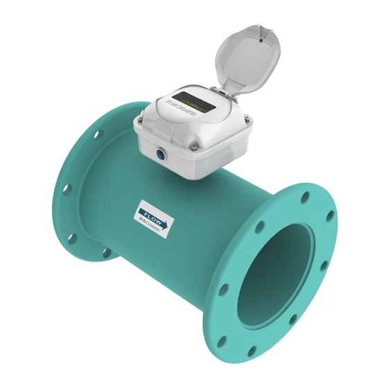
Battery powered electromagnetic flow meter
Hide thumbs
Also See for Dura Mag:
- Installation, operation and maintenance manual (27 pages) ,
- Quick start installation manual (8 pages) ,
- Instructions (4 pages)

Related Manuals for McCrometer Dura Mag


Summary of Contents for McCrometer Dura Mag
- Page 1 Dura Mag ™ Battery Powered Electromagnetic Flow Meter Installation, Operation and Maintenance Manual 30122-53 Rev. 1.6 August 13, 2019...
-
Page 2: Table Of Contents
Contents INTRODUCTION ..............1 Safety Symbols And Warnings. -
Page 3: Introduction
Safety Warnings When installing, operating, and maintaining McCrometer equipment where hazards may be present, you must protect yourself by wearing Personal Protective Equipment (PPE) and be trained to enter confined spaces. Examples of confined spaces are manholes, pumping stations, pipelines, pits, septic tanks, sewage digesters, vaults, degreasers, storage tanks, boilers, and furnaces. -
Page 4: Introduction
4-20mA outputs available. The 4-20mA output requires the optional DC power input which uses the battery as a backup power source. All Dura Mag flow meters have an internal datalogger standard, the optional datalogger software and cable is required to retrieve the stored data. -
Page 5: Dimensions And Weights
195 - 6,500 19.7” 19.0” 13.5” Dura Mag S Series meters are available in lay lengths compatible with products from other meter suppliers*. See the tables below for matched lay length options. Other Supplier Dimensions* Dura Mag - S Series Dimensions... -
Page 6: Installation
5.1.4 Grounding and Gaskets All Dura Mag flow meter installations require minimum grounding with a 12-gauge ground wire to an earth ground. Installation must conform to NEC requirements as described in section 5.4, which shows grounding for meters with minimal grounding noise. -
Page 7: Positioning The Sensor
Obstructions can include elbows, valves, pumps, and changes in pipe diameter. The uneven flow created by these obstructions can vary with each system. • Upstream Requirement: Dura Mag meters should be installed a minimum of two diameters away from of most obstructions. •... -
Page 8: Sensor Orientation
Installation 5.3.1 Pipe Diameters For proper accuracies any 90 or 45 degree elbows, valves, partially opened valves etc. should be placed not closer than two pipe diameters upstream and one pipe diameter downstream. 5.3.2 Flow Direction The flow of the medium should correspond to the direction shown by the arrow on the sensor. 5.3.3 Sensor Orientation The following installation recommendations should be followed (see Figure 2 for installation diagrams):... -
Page 9: Sensor Grounding
NEC or local grounding regulations for wiring requirements in making this connection. NOTE: The preferred method of installation is connecting the Dura Mag to its own isolated grounding rod. (Optional Sensor grounding kits are available. See Dura Mag price list, Ground Lug 30122-60, page 3.) - Page 10 Installation b. Non-conductive or internally coated pipe Sensor Ground Lug Grounding Ring Lug And When pipes are non-conductive, such as PVC or internally Grounding 12 Gauge Ground Wire coated pipe, you must substitute direct grounding with Ring Lug and grounding rings. 12 Gauge Attach the provided 12 gauge wire or equivalent to the sensor Ground Wire...
-
Page 11: Operation
General The flow meter comes pre-configured from the factory based on the installation parameters provided to McCrometer at the time of order. Other than activating the display, there is nothing required of the user for the basic operation of the flow meter. -
Page 12: Display Descriptions
Operation Display Descriptions a. Active alarms Alarm The first screen display shows any active alarms. In the Indicator sample below, there is one alarm active for an empty pipe. Alarm Type Figure 5. Display Cycle One b. Battery life Battery life remaining The second screen display shows the battery life remaining for both battery packs and the flow totalizer. -
Page 13: External Connectors
External Connectors EXTERNAL CONNECTORS 10-32VDC Power/4-20mA Output And Pulse Output The flow meter has one dedicated port and two optional ports on the back side of the electronics enclosure. (See Figure 10.) The dedicated port (center) is used to download data logger information or for meter service and troubleshooting. The two optional ports are for: Optional 10-32 VDC power and 4-20mA output Optional pulse outputs (flow volume and alarms) -
Page 14: Dc Power Cable (Optional)
DC Power Cable (Optional) DC POWER CABLE (OPTIONAL) DC Power And 4-20mA Output Cable The cable contains wiring for both the optional 10-32VDC power to the meter, and the 4-20mA output from the meter. See Figure 12 for the color scheme. Cable Jacket Black = -10-32 VDC Power (Negative) Red = +10-32 VDC Power (Positive) -
Page 15: Dc Power Supply Specifications
Pulse Output Cable (Optional) DC Power Supply Specifications Part Number: 115-12 Voltage – Input: 120 VAC ± 5% / 60 Hz (external fuse recommended) Voltage – Output: 12V ± 0.5 VDC @ 200mA Current – Output (Max): 200mA Power – 2.4W Environment: Operating Temperature: 0 to 55°C (21 to 130°F);... -
Page 16: Battery Removal And Replacement
Copyright © 2001-2019 McCrometer, Inc. All printed material should not be changed or altered without permission of McCrometer. Any published pricing, technical data, and instructions are subject to change without notice. Contact your McCrometer representative for current pricing, technical data, and instructions. - Page 17 Battery Installation and ™ 3000 Battery Removal and Replacement Replacement Shutting off the system IMPORTANT! You must follow the next steps in this speci c order to insure the unit does not reset the internal time clock. If you have the Data Logger Software and communication cable, disregard these next steps. The clock may be set with software once the unit is re-assembled.
- Page 18 Battery Installation and ™ 3000 Battery Removal and Replacement Replacement IV. Installing the batteries and restoring the power 11. If there is no strip of Velcro on the side of the chassis, remove the 12. Set the batteries in place, making sure clear adhesive protective strip from the small battery pack and press the wires extend toward the battery the entire battery pack in place as shown in the picture at right.
- Page 19 Battery Installation and ™ Battery Removal and Replacement 3000 Replacement V. Replacing the gasket If you installed replacement batteries, we recommend that you replace the gasket. If you installed new batteries, you must set the gasket in place before replacing the cover and closing up the unit. 17.
-
Page 20: Specifications
TEL: 951-652-6811 • 800-220-2279 • FAX: 951-652-3078 Lit. # 30122-59 Rev. 1.4 / 20 MAR 2019 Copyright © 2014-2019 McCrometer, Inc. All printed material should not be changed or altered without permission of McCrometer. Any published technical data and instructions are subject to change... -
Page 21: Alarm Messages
Alarm Messages 12.0 ALARM MESSAGES ALARM MESSAGE POSSIBLE CAUSE / CORRECTIVE ACTION The measured board temperature is out of the allowed range. Ensure that the B.TEMP.OUT R. instrument is operating within the specified temperature conditions: -4° to 140°F (-20° to 60°C). B1 LOW The battery ‘B1’... -
Page 22: Returning A Unit For Repair
• Call the McCrometer Customer Service Department and ask for a Return Authorization (RA) number. • Ship the meter in the original packaging, if possible. Do not ship manuals, power cords, or other parts with your unit unless required for repair. -
Page 23: Warranty Statement
The batteries and their configuration are specific TO EQUIPMENT AND PRODUCTS ARE EXCLUSIVE AND to the Dura Mag flow meter and only McCrometer batteries IN LIEU OF ANY AND ALL OTHER WARRANTIES OF can be used. Any use of batteries other than those supplied QUALITY OR PERFORMANCE, EXPRESS, IMPLIED OR from McCrometer will void the above Warranty. - Page 24 ™ Copyright © 2001-2019 McCrometer, Inc. All printed material should not be changed or altered without permission of McCrometer. Any published pricing, technical data, and instructions are subject to change without notice. Contact your McCrometer representative for current pricing, technical data, and instructions.
Need help?
Do you have a question about the Dura Mag and is the answer not in the manual?
Questions and answers