
Related Manuals for Fujitsu PRIMERGY PG-R6RC1


Summary of Contents for Fujitsu PRIMERGY PG-R6RC1
- Page 1 B7FY-2221-01 19 インチラック 取扱説明書 Standard rack User's Guide (PG-R6RC1/PG-R6RC2) (PG-R4RC5) (PG-R5RC2)...
- Page 2 はじめに PRIMERGY PRIMERGY GP5-R1TB6 GP5-R1TB7 2007 本製品のハイセイフティ用途での使用について 本書の表記 ■ 警告表示 警告 注意...
- Page 3 ■ 本文中の記号 記号 意味 ■ 製品の呼び方 製品名称 本文中の表記 40U/24U PG-R6RC1/PG-R6RC2 PG-R4RC5 PG-R5RC2 ■ リサイクルについて 各製品名は、各社の商標、または登録商標です。 各製品は、各社の著作物です。 All Rights Reserved, Copyright© FUJITSU LIMITED 2007 ...
-
Page 4: Table Of Contents
目次 1 ラック設置・運用上のご注意 ......1.1 設置場所に関する注意 ........1.2 搬入時の留意事項... -
Page 5: ラック設置・運用上のご注意
ラック設置・運用上のご注意 この章では、ラックの設置、搬入、運用上の注意事項について説明します。 設置場所に関する注意 警告 0.25G 0.25G 300Kg 1000kg 注意 1 ラック設置・運用上のご注意 ... -
Page 6: 搬入時の留意事項
搬入時の留意事項 1000 kg 室内温度 備考... -
Page 7: 設置・運用時の留意事項
設置・運用時の留意事項 ■ 通気、保守エリアの確保 500mm 400mm 200mm 1000mm 2000mm/ 900mm/ 1267mm/ 1050mm 850mm 1200mm 500mm 400mm 590mm/ 700mm 1490mm/ 1600mm * 24U/16U ■ 振動・地震対策 0.25G 警告 耐震キットはボルト等で床(スラブ)に固定してください。 固定しない場合、震度 5 を超える地震時が発生したとき、ラックが転倒するおそれ があります。 ラックが転倒した場合、ラック内の機器や周囲のものが破損したり、人が死亡また は重傷を負うおそれがあります。 1 ラック設置・運用上のご注意 ... - Page 8 ラック型名 耐震キット型名 PG-R3ST1 40U/24U PG-R6RC1/PG-R6RC2 PG-R4RC5 PG-R5ST1 PG-R5RC2 ■ 電源ケーブルの接続 警告 AC100V 3 ■ 無停電電源装置(UPS)の推奨 ■ ラックの固定について...
- Page 9 ■ スタビライザの取り付け 注意 P.11 3 19 P.22 ■ ブランクパネルの取り付け手順 注意 1 ラック設置・運用上のご注意 ...
- Page 10 ■ その他の留意事項 注意...
-
Page 11: スタンダードラック(40U / 24U
スタンダードラック(40U / 24U) この章では、スタンダードラック(40U / 24U)の構成、取り扱い手順、ラック の連結手順などについて説明します。 構成 2.1.1 仕様 項目 仕様・機能 PG-R6RC1 PG-R6RC2 PG-R4RC5 型名 仕様 基本 40U 増設 40U 基本 24U 規格 19 インチ EIA 準拠 (*1) (*1) 収納ユニット数 40U + 4U 24U + 2U 高さ×幅×奥行 2000 × 700 × 1050 mm 1267 ×... - Page 12 2.1.2 構成品 項目 数量 PG-R6RC1 PG-R6RC2 PG-R4RC5 1U 3 1U 2 2U 5 2U 4 3U 3 3U 2 (*1)...
-
Page 13: フロントドアの開き方
フロントドアの開き方 ラックキーを回し、ラックハンドルを持ち上げます。 ラックハンドルを矢印方向に回して、手前に引きます。 回してから引く 注意 2 スタンダードラック(40U / 24U) ... -
Page 14: リアドアの開き方
リアドアの開き方 ラックキーを回し、ラックハンドルを持ち上げます。 ラックハンドルを矢印方向に回して、手前に引きます。 回してから引く... -
Page 15: スタビライザの取り付け
スタビライザの取り付け 警告 ラックを設置し、ラック底面にある固定足でラックを固定します。 ラックの前後左右の面に、スタビライザを取り付けます。 前面/側面のスタビライザを 3 本のネジで、背面のスタビライザを2本 のネジでラックに取り付けます。 スタビライザを床に固定します。 1. 前面と背面のスタビライザは、2 本のネジ(またはボルト)で床に固定しま す。 2. 側面のスタビライザは、3 本のネジ(またはボルト)で床に固定します。 2 スタンダードラック(40U / 24U) ... -
Page 16: ラックの連結
ラックの連結 警告 注意 基本ラックのサイドパネルを取り外します。... - Page 17 基本ラックの、トップカバーネジおよびスタビライザを固定しているボル ト類を外します。 増設ラックの、トップカバーネジおよびスタビライザを固定しているボル ト類を外します。 2 スタンダードラック(40U / 24U) ...
- Page 18 基本ラックと増設ラックの高さを合わせます。 連結金具(上部用)を、ラックの前後に取り付けます。 上部用の連結金具は下部用に比べて幅が広く、穴も大きくなっています。 上部用と下部用を間違えないように注意してください。 連結金具を取り付ける前に、それぞれのラック底部を密着させ、ラック柱 間のすき間を上から下まで均一にしてください。...
- Page 19 ラックの前面側に、連結金具(下部用)を取り付けます。 ラックの背面側に、連結金具(下部用)を取り付けます。 2 スタンダードラック(40U / 24U) ...
- Page 20 連結したラックの前面側、背面側、上面側の3箇所に連結パッキンをはめ 込みます。...
- Page 21 手順 1 で基本ラックから取り外したサイドパネルを、増設ラックに取り 付けます。 2 スタンダードラック(40U / 24U) ...
- Page 22 19 インチ(16U)ラック この章では、 19 インチ (16U) ラックの構成、 取り扱い手順などについて説明します。 構成 3.1.1 仕様 項目 仕様・機能 PG-R5RC2 型名 仕様 基本 16U 規格 19 インチ EIA 準拠 収納ユニット数 高さ×幅×奥行 850 × 590 × 905 mm キャスター 標準添付 レベルフット 標準添付 サイドカバー 標準添付 69kg ラック質量(自重) 320kg 最大搭載質量...
-
Page 23: 19 インチ(16U)ラック
フロントドアの開き方 注意 リアドアの開き方 3 19 インチ(16U)ラック ... -
Page 24: スタビライザの取り付け
スタビライザの取り付け 警告... -
Page 25: ラック設置後の取り扱いについて
ラック設置後の取り扱いについて この章では、ラック設置後の取り扱いについて説明します。 ラックナット取り付け治具の使用手順 4.1.1 取り付け手順 4 ラック設置後の取り扱いについて ... - Page 26 4.1.2 取り外し手順...
-
Page 27: Crt 格納テーブル(Gp5-R1Tb6
CRT 格納テーブル(GP5-R1TB6) 注意 4.2.1 構成品 項目:数量 説明 CRT/LCD CRT 格納テーブル:1 台 M6 ネジ:10 個 CRT 信号延長ケーブル/ 電源ケーブル:各 1 本 ベルト:2 本 4 ラック設置後の取り扱いについて ... - Page 28 4.2.2 取り付け方法...
- Page 29 ネジ レール ストッパー金具取り付け ネジ ネジ 固定用金具 4 ラック設置後の取り扱いについて ...
- Page 31 4.2.3 CRT/LCD ディスプレイの固定方法 ■ CRT(カラー CRT ディスプレイ)の場合 固定したあとのベルト余長分は、すでに巻きつけたベルトに巻くなどして 固定してください。 4 ラック設置後の取り扱いについて ...
- Page 32 ■ LCD(カラー液晶ディスプレイ)の場合 ■ 前側ベルト固定順序 固定したあとのベルト余長分は、すでに巻きつけたベルトに巻くなどして 固定してください。...
- Page 33 ■ 後側ベルト固定順序 固定したあとのベルト余長分は、すでに巻きつけたベルトに巻くなどして 固定してください。 4 ラック設置後の取り扱いについて ...
-
Page 34: Kb テーブル(Gp5-R1Tb6
KB テーブル(GP5-R1TB6) 4.3.1 構成品 項目:数量 説明 KB テーブル:1 台 まわり止め(角穴用) :4 個 まわり止め(丸穴用) :4 個 M6 ネジ:4 個 マウスパッド 4.3.2 KB テーブルの取り付け方法 1. 左右のレールの両端に、まわり止めを取り付けます(4 箇所) 。 2. レールの左右を確認し、M6 ネジでラックに固定します。 3. レール金具で奥行きを調整し、M4 ネジで固定します。... - Page 35 1. 棚板をレールの左右に合わせて取り付けます。 2. 左右のレールの前面側に M3 ネジでストッパーを取り付けます。 3. スライドラッチをストッパー金具に引っ掛け、前面のパネルを固定します。 4.3.3 取り扱い時の注意 注意 ・ キーボードテーブルにひじをつかないでください。テーブルが破損することが あります。 ・ キーボードテーブルを引き出した状態で、キーボードテーブルより下にある装 置の操作を行う場合は、頭上のキーボードテーブルに十分注意してください。 キーボードテーブルにぶつかり、けがの原因となることがあります。 4 ラック設置後の取り扱いについて ...
-
Page 36: 汎用テーブル(Gp5-R1Tb7
汎用テーブル(GP5-R1TB7) 4.4.1 構成品 項目:数量 説明 汎用テーブル:1 台 M6 ネジ:8 個 ベルト:2 本 4.4.2 取り付け方法... - Page 37 4.4.3 取り扱い時の注意 ・ 汎用テーブルに装置を搭載した場合には、必ず添付のベルトを使用して装置を 汎用テーブルに固定してください。 4 ラック設置後の取り扱いについて ...
-
Page 38: ケーブルホルダーの使用手順
ケーブルホルダーの使用手順 ■ スタンダードラック(PG-R6RC1/PG-R6RC2)の場合... - Page 39 ■ スタンダードラック(PG-R4RC5)の場合 4 ラック設置後の取り扱いについて ...
- Page 40 ■ 19 インチ(16U)ラック(PG-R5RC2)の場合...
- Page 41 Before Reading This Manual Thank you for purchasing a Standard rack for the PRIMERGY. This guide describes various precautions to be observed when handling components, including the Standard (40U) Rack (PG- R6RC1), Extension (40U) Rack (PG-R6RC2), Standard (24U) Rack (PG-R4RC5), Keyboard and CRT Housing Table (GP5-R1TB6), and the General-purpose Table (GP5-R1TB7).
- Page 42 When scrapping this product, contact an office listed in "Appendix A Contact Information" ( pg.75). This product must be disposed of as industrial waste. Product names used are trademarks or registered trademarks of their respective manufacturers. Products are copyrights of their respective manufacturers. All Rights Reserved, Copyright© FUJITSU LIMITED 2007...
- Page 43 Contents 1 Precautions for Rack Installation and Use ....Installation Site Precautions ....... Precautions during transportation .
-
Page 44: Precautions For Rack Installation And Use
Precautions for Rack Installation and Use This chapter explains the precautions for rack transportation, installation, and use. Installation Site Precautions WARNING • Never place the rack in an unstable location subject to excessive vibrations (over 0.25G), or a location that is not level. Doing so may cause the rack to tip over, resulting in serious injury. -
Page 45: Precautions During Transportation
Precautions during transportation This section explains the precautions needed when transporting this product. • When transporting the rack, check beforehand that the width of the route to be used is wider than the rack. • Use of a board may be necessary when there is a bump in the transportation route. [Device] Board (steel plate etc.) •... -
Page 46: Precautions For Installation And Use
• Keep the key provided with the rack safe, make sure not to lose it. Key is here K ey closes for the key Front door Condition at purchase Precautions for Installation and Use Provide adequate clearance for ventilation and service Provide adequate clearance for ventilation and service, as shown below. - Page 47 • Quake Proof Stabilizer Rack Type Quake Proof Stabilizer Type Standard rack (40U/24U) PG-R3ST1 (PG-R6RC1/PG-R6RC2/PG-R4RC5) Connecting the power cable • Connect the power cable for each rack-mount unit to a power supply with adequate power for the configured rack system. Refer to the instruction manual provided with each unit to determine unit power consumption.
- Page 48 Mounting stabilizers for prevent falling CAUTION • Always use the stabilizers when installing the rack. If not secured in this fashion, the rack may tip over when a unit is drawn out. Mouting blank panel CAUTION • If the blank panel is NOT installed, the exhaust turns forward and it is inhaled again.
- Page 49 Other precautions CAUTION • Do not remove the front or rear doors of the rack. The sheer weight of these doors may result in serious injury if they fall over. If the doors must be removed, please contact our service engineers. •...
-
Page 50: Standard Rack (40U/24U)
Standard Rack (40U/24U) This chapter explains the configuration of the standard rack (40U/24U), handling procedure, rack connection procedure, etc.. Composition The followings shows the specifications and components of a standard rack. 2.1.1 Specification Item Specifications and functions TYPE NAME PG-R6RC1 PG-R6RC2 PG-R4RC5 Type... - Page 51 2.1.2 Components Item Quantity TYPE NAME PG-R6RC1 PG-R6RC2 PG-R4RC5 Blank panel 1U : 3 1U : 2 2U : 5 2U : 4 3U : 3 3U : 2 Screw (M6) Rack nut (M6) Spring nut Cable holder Screw (M5) Release tie rack nut insertion tool Stabilizer...
-
Page 52: Opening The Front Door
Opening the front door Unlock the door with the key for the rack. Lift up the handle. To open, pull the projecting handle up and to the left. Up and to left CAUTION • Close the front door after securing the installed device completely. Not doing so may lead the device to fall in the event of an earthquake and cause the device failure. -
Page 53: Opening The Rear Door
Opening the rear door Unlock the door with the key for the rack. Lift up the handle. To open, pull the projecting handle up and to the right. Up and to right 2 Standard Rack (40U/24U) -
Page 54: Mounting Stabilizers For Prevent Falling
Mounting stabilizers for prevent falling Mount the stabilizers to secure the rack to the installation site. WARNING • Always use the stabilizers when installing the rack. If not secured in this fashion, the rack may tip over when a unit is drawn out. The procedures for mounting the stabilizers are given below. -
Page 55: Rack Connection
Rack connection To expand the rack, connect another rack to the existing one (base rack). One expansion rack may be mounted to the base rack. For a maximum of two racks (40U type) including the base rack. WARNING • To reduce the risk of equipment damage and electric shock, switch off power for the server unit and peripherals and unplug the power cable before connecting the rack. - Page 56 Remove the bolts and screws from the base rack. Unscrew the two screws securing the top cover to the rack, the bolts securing the stabilizer to the rack. Screw of top cover Plain washer (M8) Spring washer (M8) Hexagon head bolt (M8) Remove the bolts and screws from the extension rack.
- Page 57 Align the height of the extension rack to that of the base rack. Line up the side of the extension rack with the side of the base rack and move the feet of the extension rack up and down to adjust the height to the base rack. Base rack Extension rack Attach mounting fixtures for upper to the base rack and connect...
- Page 58 The upper mounting fixture is wider, and its holes are bigger than the lower mounting fixture. Do NOT mix up the upper and lower ones. Before attaching the mounting fixtures, push the bottom of the racks together and equalize the space between the rack pillars from the top to bottom.
- Page 59 Attach the shield rubber on the front,rear,and top sides of the connected rack. Set each shield rubbers between the frames of rack. Shield rubber for holizontal Shield rubber for vertical 2 Standard Rack (40U/24U)
- Page 60 Mount the side panel removing from base rack. Attach the side panel removing from base rack with screws. Screws (M4)
-
Page 61: Handling The Rack After Installation
Handling the rack after installation This chapter explains handling the rack after installation. Using the rack nut insertion tool 3.1.1 Insertion Insert one edge of the rack nut into the hole. Install the rack nut from the inside of the mounting flange. the side of pillar Rack nut Insert one edge of... - Page 62 Pull the tool and set the rack nut. the side of pillar Pull the tool while pushing the rack nut back (Arrow direction) 3.1.2 Removal Insert the edge of tool into the gap of rack nut and mounting flange. Then compress the edge of the rack nut. Push down on the tool and remove it.
-
Page 63: Crt Housing Table (Gp5-R1Tb6)
CRT Housing Table (GP5-R1TB6) CAUTION • Contact our service engineers before replacing the display unit. Improper or careless replacement of the display unit may result in dropping the display, leading to potential injury. 3.2.1 Components Item: Quantity Description CRT housing table: 1 Table to install 15-inch CRT/LCD in the rack M6 screw: 10 To secure the CRT table to the rack... - Page 64 Secure stopper to the left rail with screws. Stopper Spacers Screws Secure rails that were assembled in Step 1 to the rack. Screw Rail Stopper Screw...
- Page 65 Secure fixtures to the CRT housing table. Screws Fixtures Install the CRT housing table in the rack and secure stoppers with screws. Attach the cover to the front of the rack. Stoppers Screws Screw Cover Screws Screw CRT housing table [Front] 3 Handling the rack after installation...
- Page 66 3.2.3 Securing the CRT/LCD display For CRT (color CRT display) Place the CRT so that its base is wedged under the bracket of the table. Bracket CRT base Front Table Buckle up the CRT by putting the supplied belts through the holes in front and back of the table.
- Page 67 For LCD (color liquid crystal display) Place the LCD so that its base is shoved under the bracket of the table. Bracket LCD base Front Table Buckle up the LCD by crisscrossing the supplied belts through the holes in front and back of the table. Front belt fastening procedure Wrap it around Belt...
- Page 68 Rear belt fastening procedure Wrap it around the front Belt of the LCD base Front Do not leave the fastened belt ends dangling. Take precaution such as wrapping them around the secure part of the belt.
-
Page 69: Keyboard Table (Gp5-R1Tb6)
Keyboard Table (GP5-R1TB6) 3.3.1 Components Item: Quantity Description This slide-type table houses the rack keyboard and KB table: 1 unit mouse. Baffle (for square hole): 4 To secure the KB table to the rack Baffle (for circular hole): 4 M6 screw: 4 This is designed to adhere to the table with double-sided Mouse pad: 1 piece tape. - Page 70 Attach a shelf board to the rack and secure it with stoppers. 1. Align a shelf board with the left and right of rails and attach it to the rack. 2. Secure stoppers with M3 screws on the front of the left and right rails. Insert a screwdriver into the circular hole on the side of the rail to attach the stoppers.
-
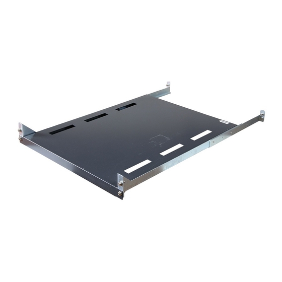
Page 71: General-Purpose Table (Gp5-R1Tb7)
General-purpose Table (GP5-R1TB7) 3.4.1 Components Item: Quantity Description This table is used to mount an exterior DLT unit or other General-purpose table: 1 unit components. M6 screw: 8 To secure the general-purpose table to the rack These belts are used to secure the unit mounted on the Belt: 2 sets general-purpose table. - Page 72 Install the table to the rack; fix the table with two screws. Secure the fixture to the table. Screws Fixture General-purpose table Screws Screws General-purpose table [Front] 3.4.3 Handling precautions CAUTION • Use the belts provided when mounting the unit to the general-purpose table.
-
Page 73: How To Use The Cable Holder
How to Use the Cable Holder The various server connection cables may be tidied up by securing them to the supplied cable holder. Standard Rack (PG-R6RC1/PG-R6RC2) Prepare the necessary components. The necessary components are supplied with the rack. Cable holder Spring nut M5 screw Attach the cable holder to the rear pillar of the server rack with... - Page 74 Secure the cable connected on the back of the server to the release tie with the cable holder. Server Release tie Cable holder Cables Rack rear Press part A to unlock and undo the release tie. Standard Rack (PG-R4RC5) Prepare the necessary components. The necessary components are supplied with the rack.
-
Page 75: Appendix A Contact Information
Fax: +852-2827-4724 Address: 10/F., Lincoln House, 979 King's Road Taikoo Place, Island East, Hong Kong • Indonesia: PT. Fujitsu Systems Indonesia Offices Headquarters Tel: +62-21-570-9330 (Hunting) Fax: +62-21-573-5150 Address: Wisma Kyoei Prince 10th Floor Jl. Jend. Sudirman Kav 3-4 Jakarta, Indonesia 10220 •... - Page 76 Address: Unit 802-8th floor, Fortuna Tower Hanoi 6B Lang ha Street, Ba dinh District, Hanoi Socialist Republic of Vietnam • United States: Fujitsu Computer Systems Corporation Tel: +1-800-831-3183 Fax: +1-408-496-0575 Address: 1250 East Arques Avenue, Sunnyvale, CA USA 94088-3470 For the latest information, refer to the Fujitsu PRIMERGY website (http://primergy.fujitsu.com).
- Page 77 ● 落丁、乱丁本は、お取り替えいたします。 • The contents of this manual may be revised without prior notice. • Fujitsu assumes no liability for damages to third party copyrights or other rights arising from the use of any information in this manual. • No part of this manual may be reproduced in any form without the prior written permission of Fujitsu.
- Page 78 こ のマ ニ ュ アルは再生紙を使用 し 、 リ サイ ク ルに配慮 し て製本 さ れています。 不要にな っ た際は、 回収 ・ リ サイ ク ルに出 し て く だ さ い。...