
Related Manuals for Mitsubishi Electric PLK-G3040R


Summary of Contents for Mitsubishi Electric PLK-G3040R
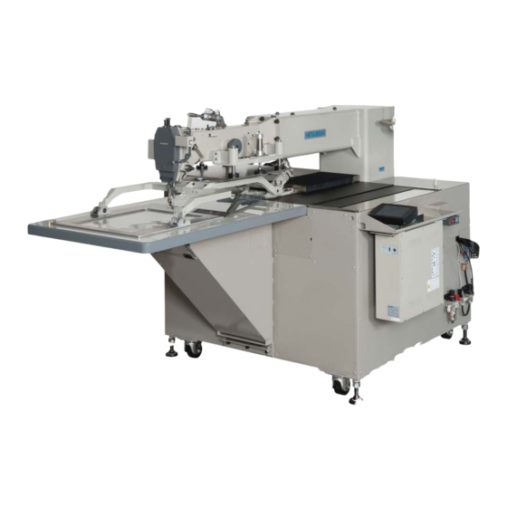
- Page 1 Industrial Sewing Machine TECHNICAL MANUAL SEWING MACHINE HEAD Electronic Pattern Sewing Machine Model PLK-G3040R A180E664P02...
- Page 2 FOR SAFE USE Before the installation, operation, and inspection for this product, read the “FOR SAFE USE” and the technical manuals carefully. Also read the other technical manuals, “Control Unit” and “Operation Panel” describing some instructions, which are not in this manual, and use the sewing machine properly. SAFETY INDICATIONS Indicates that incorrect handling may cause hazardous conditions, resulting DANGER...
-
Page 3: Safety Precautions
SAFETY PRECAUTIONS DANGER To prevent from receiving an electric shock, always turn off a power switch and unplug power supply when opening a control box, and then open after ten minutes passes. CAUTION USAGE ENVIRONMENT Please do not operate the sewing machine under the following conditions. (1) In the ambient temperature of 35 degrees (95°F) or more than 35 degrees, or the ambient temperature of 5 degrees or less than 5 degrees (41°F). - Page 4 SEWING (1) Please make sure to turn the power switch off before installing or replacing needles. (2) Please pay attention for the fingers not to be injured by the needle point. (3) Please make sure to turn power switch off before lubricating. (4) Please pay attention that oil does not get on your skin or in your eyes as it may cause an inflammation.
-
Page 5: Table Of Contents
CONTENTS 1. STRUCTURE OF THE SEWING MACHINE··································· 2. SPECIFICATION······································································ 3. INSTALLATION······································································· 3-1. Securing the Sewing Machine Table························································ 3-2. Connection of the air tube····································································· 3-3. Installation of the foot switch, and connection of the control cables ················ 3-4. Installation of the thread stand································································ 4. - Page 6 7. STANDARD ADJUSTMENT······················································· 7-1. Adjustment of the thread take up spring tension········································· 7-2. Adjustment of the thread take up spring swing stroke·································· 7-3. Adjustment of slackness of tension discs of thread tension regulator (lower)···· 7-4. Adjustment of slackness of tension discs of thread tension regulator (upper)···· 7-5.
- Page 7 9. HOW TO SET UP IF YOU USE THE TWO STAGE WORK HOLDER·· 9-1. How to set up······················································································ 9-2. Input and output configuration································································· 9-3. Air piping···························································································· 10. TROUBLESHOOTING····························································...
-
Page 8: Structure Of The Sewing Machine
1. STRUCTURE OF THE SEWING MACHINE PLK-G3040R electronic pattern sewing machine consists of the following main parts. Detector Cotton stand Manual pulley Bobbin winder X・Y table Halt switch cover Presser foot regulating screw Power switch Presser foot Table Presser plate... -
Page 9: Specification
2. SPECIFICATIONS Model PLK-G3040R X-direction (left/right) 300 mm Sewing area Y-direction (front / back) 400 mm Maximum sewing speed 1,000 rpm (for stitch length of less than 4 mm) Setting speed 10 speed levels in 200 rpm to 1,000 rpm Stitch length 0.1 to 20.0 mm... -
Page 10: Installation
3. INSTALLATION CAUTION (1) Please have some specialists, who have enough experience for the sewing machine installations, install the sewing machine. (2) Please have a Qualified Electrician perform necessary electric wiring. (3) Please do not operate until the sewing machine is repaired when any damage or fault is found on the sewing machine at the installation. -
Page 11: Connection Of The Air Tube
3-2. Connection of Air Tube (1) Connect the attached tube between the joint E of air pressure control unit (see the lower fig.) and the compressor. (2) Turn the residual pressure exhaust valve lever to right. Compressed air is fed from IN to OUT and supplied to the air cylinder through a solenoid valve. -
Page 12: Installation Of The Foot Switch, And Connection Of The Control Cables
3-3. Installation of the foot switch, and connection of the control cables Connect the foot switch to the connector CON H. The foot switch is enclosed in the accessory box. Control cable to connect to already be connected as shown on the figure below. CON A: Operation panel CON A CON B... -
Page 13: Lubrication
4. LUBRICATION CAUTION (1) Please make sure to turn power switch off before lubricating. (2) Please pay attention that oil does not get on your skin or in your eyes as it may cause an inflammation. (3) Please make sure to keep oil out of the reach of children who may drink oil by mistake. (4) Please make sure to lubricate when operating for the first time after the installation. -
Page 14: Proper Operation
5. PROPER OPERATION 5-1. Initial setting of the control box When using the sewing machine for the first time, the model and the language of the sewing machine in use have to be set. Refer to the instructions in the paragraph “[6] Initial Setting of System (Model/language Setting)” in the CONTROL UNIT technical manual. -
Page 15: Threading The Upper Thread
5-3. Threading the upper thread CAUTION (1) Please turn the power switch off when threading a needle. The needle thread should be threaded, as shown on the figure, with the thread end extended about 4 cm from the needle. Thread tension Cotton stand guide Thread tension... -
Page 16: Winding The Bobbin Thread
5-4. Winding the bobbin thread CAUTION (1) Please do not touch the rotating part during winding thread. Doing so may cause injury and/or the machine failure. (2) Please make sure to pull the upper thread out of the needle before winding the bobbin thread. (1) Route the thread as shown in the below figure then, wind the thread to the bobbin (No.1) in the direction of “a”... -
Page 17: Setting The Bobbin
5-5. Setting the bobbin (1) Set a bobbin in the bobbin case. (2) Raise the bobbin holding lever A of bobbin case to set. (3) Introduce the thread in the cut groove B of bobbin case and pass through the thread hole C. (4) Pull the thread and confirm the bobbin turns in Turn direction the counterclockwise direction. -
Page 18: Sewing
6. SEWING CAUTION (1) Before starting the sewing, please make sure the position and the function of the halt switch. (2) Please do not touch the operating parts during sewing operation. (3) It is very dangerous to operate the sewing machine without safety guards (eye guards, belt covers, link covers, finger guards or the others). -
Page 19: Operation Of The Halt Switch
6-2. Operation of the halt switch (1) If accidents such as a thread breakage, needle breakage and others happened during the sewing, press the halt switch immediately. The sewing machine stops instantly. (2) To cancel the halt state, press the halt switch again. (3) When continuing sewing, step on the grey foot switch to restart at the halted position. -
Page 20: Thread Tension
6-3. Thread tension Attain a balance between the needle thread tension and bobbin thread tension. (1) As shown in Figure, the optimum tension balance is yielded when the needle thread is interlocked with the bobbin thread along the center line of the fabric layers. ○... -
Page 21: Standard Adjustment
7. STANDARD ADJUSTMENT CAUTION (1) Please make sure to turn the power switch off before adjusting the sewing machine. (2) When adjusting the sewing machine with the power switch on, please be careful not to step on the foot switch by mistake. (3) Please be careful not to be injured by a sharp part such as the needle and the shuttle hook point. -
Page 22: Adjustment Of Slackness Of Tension Discs Of Thread Tension Regulator (Lower)
7-3. Adjustment of slackness of tension discs of thread tension regulator (lower) 0.8~1.0mm (1) Raise the presser foot. (2) Slacken set screw A of thread tension regulator. (3) Adjust the bushing position in the arrow direction in the figure to adjust the slackness at 0.8 to 1.0 (4) After the adjustment, tighten the set screw of Adjustment thread tension regulator. -
Page 23: Operation And Adjustment Of The Work Holding Device
7-5. Operation and Adjustment of the work holding device Work holding device is largely divided to the clamp frame assembly, which clamps the sewing cloth, and the work holder assembly which prevents the lift of clamp frame assembly. 7-5-1. Holding motion Control and operation before the sewing cloth is clamped and the stitching starts are conducted with following sequence. -
Page 24: Adjustment Of The Holding Pressure
7-5-2. Adjustment of the holding pressure Air pressure to the air cylinder, which drives respective mechanisms of work holding device, consists of following 2 lines. Refer to the paragraph 3-2 and adjust. Main circuit : 0.4 MPa ・・・ Work holder up/down, clamp frame up/down (There are the thread release, presser foot and bobbin thread trimming in addition to the above.) Slider circuit : 0.2 ±... -
Page 25: Adjustment Of The Hook Position
7-7. Adjustment of the hook position (1) Loosen hook set screw A. (2) Turn the hook and adjust the timing of hook head B. * Hook head timing With the standard timing, the following relation is established when the needle bar is lifted 4.5 mm from the lowest position. -
Page 26: Adjustment Of Up/Down Motion Extent Of The Presser Foot
7-8-2. Adjustment of up/down motion extent of the presser foot Up/down motion extent of presser foot can be adjusted with 3 steps of 0, 5 and 10 mm. When the connection of stepped screw between the link and the arm is as shown by figure of section 7-8-1, the up/down motion extent is 10 mm, it is 5 mm when connected with the screw hole A or 0 with the screw hole B. -
Page 27: Air Pipes Related
7-9. Air Pipes Related Outline pipe arrangement from the pneumatic pressure control unit to the machine is as shown on the figure. (1) Straight joint, which relays the pipe to the bobbin thread trimming air cylinder, and connector, which relays the sensor cable of said air cylinder, are arranged at the section indicated with the arrow. When the machine head is removed from the table, it is necessary to disconnect the straight joint and the wiring connector. -
Page 28: Adjustment And Maintenance
8. ADJUSTMENT AND MAINTENANCE 8-1. Adjustment of the bobbin winder (1) Adjusting the winding volume To reduce the winding volume, first loosen screw A and move the adjust lever toward the bobbin, conversely, to increase the volume, move it in the opposite direction. The adjust lever is set so that it will return in the direction of arrow “a”... -
Page 29: Adjustment Of The Home Position
8-2. Adjustment of the home position Mechanical home position is adjusted at the position shown on the figure. This position can be adjusted finely within the range to show to the list shown below but it is impossible to move the position itself (change of home position). -
Page 30: Fine Adjustment Of The Home Position In X Direction
8-2-1. Fine adjustment of the home position in X direction (1) Remove the left cover (black plastic) of X-Y table and set it as shown on the figure. (2) Loosen two places of screw A. The home position moves to a course same as detection plate movement when you move detection plate to arrow C. -
Page 31: Adjustment Of The X-Y Table Belt Tension
8-3. Adjustment of the X-Y table belt tension 8-3-1. Adjustment of X-axis timing belt tension (1) Remove the right and cover of X-Y table (silver color-plated steel plate). (2) Loosen lock screw B (4 pieces) of bracket A, turn the adjust bolt C to adjust the tension of timing belt (3) Belt is tensed as the adjust bolt C is screwed in firmly. -
Page 32: Adjustment Of The Position Detector
8-4. Adjustment of the position detector 8-4-1. Adjustment of the stop position (UP position) of the needle bar (1) When the stitching is over, the machine stops with the take-up lever at the highest position. (2) When the position is displaced more than 3 mm, loosen the set screw of detector and turn the joint to adjust the stop position correctly. -
Page 33: Adjustment Of The Thread Trimming Mechanism
8-5. Adjustment of the thread trimming mechanism This thread trimming mechanism employs the air driven knife operation, which consists of the knife section which is assembled on the slide plate (center) and the knife section which is assembled on the bed and driven by cylinder. -
Page 34: Adjustment Of The Movable Knife Stroke
8-5-2. Adjustment of the movable knife stroke Relation of movable knife, when it protruded, Cylinder mount Movable knife guide and the needle hole is as shows on the figure. plate Adjustment is made by changing the position Knife drive arm Cylinder of cylinder mount plate. -
Page 35: Belt Tension Adjustment Of The Machine Head Drive System
8-6. Belt Tension Adjustment of the machine head drive system Lower figure shows the drive transmission route of machine motor. Drive with motor is transmitted to the intermediate lower shaft via V belt and divided there to 2 lines of upper and lower shafts. Timing belt A transmits the drive to the intermediate upper shaft and the upper shaft, which is connected with the coupling, drives the needle bar. -
Page 36: Adjustment Of The Lower Shaft Timing Belt Tension
8-6-2. Adjustment of the lower shaft timing belt tension (1) Remove the bed cover directly under the table, which accommodates the machine head. (2) Move the tension pulley E, which is installed in front of the main unit frame, in the arrow F direction and adjust the tension so that the timing belt B will not be warped with a light pressing. -
Page 37: Input And Output Configuration
9. HOW TO SET UP THE TWO STAGE WORK HOLDER If two stage work holder is required, the device is necessary to be prepared by user side. Following is example for typical setting of two stage work holder. Example : How to press the work holder foot switch(Foot switch black) to the pressing operation of the first, and press the newly added switch to the pressing operation of the second. -
Page 38: Troubleshooting
10. TROUBLESHOOTING CAUTION (1) Please make sure to turn the power switch off before adjusting the sewing machine. (2) If the adjustment is required while the power switch on, do not step on the foot switch by mistake. Condition Cause Corrective action Reference Upper thread tension is too... - Page 39 Bobbin thread tension is too Stitch forming is loose. Adjust bobbin thread tension. loose. Strength of thread take up Adjust strength of thread take spring is inadequate. up spring. Presser foot position is not Adjust presser foot position proper. properly. Presser foot up and down Adjust presser foot up and timing is not proper.
- Page 40 FACTORY AUTOMATION SYSTEM GROUP 2-7-3, Marunouchi Chiyoda-ku Tokyo 100-8310, Japan Fax : +81-3-3218-6821 New publication, effective SEP.2012 Contents subject to change without notice...