Table of Contents
Advertisement
Advertisement
Table of Contents

Subscribe to Our Youtube Channel
Summary of Contents for Enseo Hd2000 RF
- Page 1 page 1...
-
Page 2: Table Of Contents
18. FC C Stat em ent & L ice nse Ac k nowl e dg em en t ....... 22 19. Enseo Li m i t ed Wa rra nty/ Software Ma i ntena nce A g re e m e nt ..........23 20. -
Page 3: Introduction
Introduction The HD2000RF is a professional tri-band tuner providing 8VSB, QAM and NTSC tuner designed for use in hospitality applications. The HD2000RF is configured with hardware components that enable future expansion to support IPTV and IP VOD system requiring Ethernet connections. These components are disabled in software to focus the applica- tion use of the HD2000RF to coax systems only. This document outlines the installation, set up and operation of the HD2000RF in a standard hospitality operation with a compatible LG Electronics display using either MPI or Serial control. Supplied Accessories HD2000 RF HDMI Data 12V DC Cable Set Top Box Cable Power Supply Note on Compatible Displays: The HD2000RF is designed for connection and integrated control with LG Electronics commercial displays utilizing either a hospitality MPI (RJ12) connector or serial (DB-9) connector. page 3... -
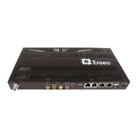
Page 4: Connections
L/R Stereo L/R Stereo Display Ethernet USB x 2 Audio Out Audio In Control Installation Installing Cables: 1. Remove AC power from LG TV and HD2000 RF. 2. Install the HD2000 RF, connecting the signal source to the HD2000 RF and the HDMI cable to the LG TV. 3. Connect the TV control cable (220-0281-003) to the LG TV. Do not connect the TV control cable to the HD2000 RF yet. Select TV Type on the HD2000 RF: 4. Apply power to the TV and turn it on using the LG remote. 5. Select TV HDMI-1 input with LG TV remote (not included). 6. Apply AC power (plug-in power, not the PWR button) to the HD2000 RF and wait 1 minute for the HD2000 RF to properly boot. page 4... - Page 5 7. Using the Enseo remote (not included), press 0-MENU-7-8-9. • During Step 7, aim the remote at the HD2000RF, not the TV. • If the sequence was successful, the HD2000 RF will turn on and display the setup channel. 8. Press SETUP on the Enseo remote and navigate to Service Options/TV Interface Type. Select the appropriate type. TV will display “Please Wait Restarting...” and reboot. Completing the Setup: 9. While the HD2000 RF is rebooting, connect the TV control cable to the HD2000 RF (it should already be con- nected to the TV). • When the TV has completed its reboot and gained control of the TV, it will power down the TV. • From this point, one can use either the Enseo or the LG remote to issue commands. VIDEO AUDIO OUT DIGITAL RF IN CONTROL NETWORK AUDIO AUDIO POWER HDMI DISPLAY PPV page 5...
-
Page 6: Menus/Configuration
LG Escape Sequence* *If you incorrectly selected a panel type or use another manufacturer’s TV, use the fol- lowing method to reset the HD2000 RF to Generic Mode: 1. Make sure no TV control cable is connected to the HD2000 RF. 2. Make all other connections (HDMI, network, RF, etc.), but DO NOT APPLY AC to the HD2000 RF yet. 3. Turn on the TV using the manufacturer’s remote. 4. Apply AC to the HD2000 RF. 5. While the HD2000 RF boots up, depress and hold the UP button of the Enseo remote. • The HD2000 RF will detect the UP button IR, switch to Generic Mode, then power up. -
Page 7: Video-On-Demand Setup
Video-On-Demand Setup The Enseo HD200RF is designed to automatically configure itself with many Video-On-Demand systems, including LodgeNet™ (Terminal required). To operate with these systems, connect the HD2000RF to the LG TV using the correct data cable for the model used, and connect the VOD system to the PPV Control port using a data cable provided by the VOD system integrator. To access user menus and to adjust settings for the HD2000RF, the PPV Control data cable must be disconnected from the VOD system. Manual Set Up Menu The HD2000RF is shipped with an Enseo remote control that includes a set up button for access to the set up menus. Navigating Menus: Most menus and submenus are navigated using the UP/DOWN/RIGHT/LEFT arrows on the remote control. To enter a menu, press the RIGHT button. To enter an item in a sub menu, the ENTER button can be pressed or the LEFT arrow button can be pressed to exit a entry field and store the setting. Some sub-menus require specific characters and onscreen instructions will be provided in such cases. Image 1 - Setup Menu page 7... -
Page 8: Channel Options
Channel Options The HD2000RF supports analog and digital channels from cable or over-the-air sources (NTSC/QAM/ 8VSB). In ad- dition, the HD2000RF can map IP streams (UDP/RTSP/RTP) to channels for a blended IP / RF experience. Note: • Air – To receive over-the-air channels, an antenna and additional equipment may be required • Cable – Digital cable channels may not be accessible if conditional access or subscriptions are required Image 2 – Channel Options Menu Tuning Mode Option is either Air (Over-The-Air) or Cable. This setting can be changed using RIGHT arrow button to enter the set- ting and using UP or DOWN select either Air or Cable. To save the setting, press the LEFT arrow button. Edit Channel List A submenu with functions to add, delete and manage information regarding channels Clear Channel List Used to delete the stored channel list programming Auto Channel Install Used to scan and install channels. Analog channels will be automatically entered into the channel ring, but digital channels must be entered manually. Digital Channel Search Used to search for digital channels available. Note, these channels will not be automatically entered into the channel lineup. Digital channels require manual entry using the Edit Channel List menu. page 8... - Page 9 Edit Channel List Submenu This submenu allows for manual add, delete and management functions of channels. Image 3 – Edit Channel Submenu Channel Using remote, enter the number of the channel to manage, or to setup the Startup Channel, select Startup Channel The Startup Channel is a feature to have a specific channel tuned as the default whenever the TV turns on. The Startup Channel may also be an AV Input in the case where an external media device is used for the PPV system. A Startup Channel does not need to be a channel that is in the channel ring. Include in List This function allows a channel to be removed from the Channel Ring (available channels) without losing stored data. Select Yes to include / No to exclude Type • Selection options include: 1. Analog – Analog NTSC Channels from 1-125 2. Digital – Digital Channels – Select Digital to remap the digital QAM or 8VSB channel to an analog channel number 3. A/V Input – Provide access to TV A/V Inputs through remapping the input to a channel ring number.* *Note: A/V Input remapping may not function with all PPV providers. For details on using A/V Inputs while in page 9 Lodging Mode, consult the section on A/V Input mapping.
- Page 10 2. Selection Method - Digital streams may contain information Image 6 – Digital Channel Options that allow for the creation of virtual channels. For example, station WXYZ may transmit on channel 14.1, but include infor- mation that describes the channel as 8.1. This is done in situations where name branding has occurred and the station still wants to be identified with its old allocation. In the example above, 14.1 is the direct channel and 8.1 is the virtual channel. The Enseo unit is able to capture and interpret these virtual channels. When setting up your channel ring, you may choose between the virtual channel ID or the actual channel information. 3. Digital Channel - This section provides for the entry of the Channel Primary digits and Sub (Program) digits for the known digital channel 4. Label - Entry using UP / DOWN arrow buttons to enter a text label for the channel Note: PPV systems may not use the label setting in the HD2000RF and instead use own label method. Confirm...
- Page 11 5. Logo - Selectable menu of graphical logos for adding a visual thumbnail for many popular TV channels (Note: PPV systems may not use the logo setting in the HD2000RF and instead use own logo method. Confirm with your PPV provider if label information will be used) Image 7 – Logo Options 6. Usage - Selection of Audio and Video (default), Audio Only for music channels/inputs or Video Only for video only usage. 7. Allow Online Remapping - Not all PPV systems allow Online remapping. Please consult Enseo at 972-234- 2513 to ensure your system is supported. This setting is used for Lodging Mode to allow remapping of a Digital Channel or AV Input to exist in a controlled hospitality system. Select YES to have the settings for the channel specified maintain the mapped information. Analog tune commands are the only tune commands that can be re-mapped. If your PPV provider does not use ana- log tune commands they will need to implement them before this function will work. Before this function is used the PPV provider must be consulted due to differences in command structures between PPV providers, the necessity to include the re-mapped channel in the ring, and other proprietary concerns. Image 8 – Online Remapping Selection page 11...
-
Page 12: Switch-On Options Menu
Lodging System Requirements for Channel Re-mapping: 1. The Lodging System MUST NOT explicitly ‘delete’ the channel 2. The Lodging System MUST NOT add ‘installation data’ for the channel 3. The Lodging System MUST use an ‘Analog Channel Tune’ command to access the re-mapped channel Switch-On Options Menu This menu provides options for setting up default settings for when the display first turns on. These settings are par- ticularly useful in a lodging environment to be sure the display starts on the Startup Channel and to pre-define volume, screen format and other settings. Image 9 – Switch-On Options Menu 1. Channel - Allows for the configuration of a default channel: • None – Allows PPV system to define startup channel • Startup Channel – Uses the information configured for Startup Channel on Edit Channel Submenu. This may include an A/V Input. Note: Pro:Idiom encrypted channels are not supported as startup channels at this time. • Restore – Returns the TV to the last channel tuned prior to turning off by user 2. Volume - Set the numeric value from 0 to 99 that you would like to be used as the default volume level for the display. 3. Picture Format - Select between different formats for the screen and content presented. Options include: • Native - This setting will show the aspect ratio of the source material. 4:3 NSTC images will be shown page 12... -
Page 13: On-Screen Display Options
with side bars. • Widescreen - This setting will fill the screen with the image by stretching the image (if necessary) to create a 16:9 image. 4. Power - Select the behavior for the HD2000RF when AC power is lost and restored. Settings include: • Standby – Return to a standby mode if power is lost or on first plug in • Force On – Turn on TV and Tuner if power is lost or on first plug in. Force On mode may cause TV to turn on in lodging environment following power outage. • Restore – Restores the TV to its previous power state after a loss and recovery of power. 5. ON>OFF Hold Off Timer - This setting allows for a selectable period of time where the HD2000RF will ignore additional IR button presses during a power off process. This feature is used when guests may have situa- tions where extra IR presses are causing undesirable interaction. 6. OFF>ON Hold Off Timer - This setting allows for a selectable period of time where the HD2000RF will ignore additional IR button presses during a power on process On-Screen Display Options The On-Screen Display Options settings provide for customization and set up of OSD options. Image 10 – On-Screen Display Options Menu 1. Show Volume Indicator - This menu item is a Yes/No selection for whether a visual representation on the volume adjustment should be shown on the screen when the user uses the volume up or down on the remote. -
Page 14: Control Options
2. Use 3-Digit Entry - This menu item is a Yes/No selection for support of 3-digit numbers for channels over 99 and digital channels that may use a sub-digit 3. Show Channel Guide - This menu item is a Yes/No selection for whether a channel guide is active for the user to see the available channels on the display. Channel Guide content is generated by the analog channel numbers and text labels for each channel. 4. Channel Banner Contents - This menu item allows the selection of the content available on the display ban- ner. Use the 0 button when selecting or deselecting an option on this sub-menu. Selections include: • Show number: The channel number • Show Label: The text label for a channel • Show Logo: The select graphic if any 5. Welcome Message Options - This menu item provides for a way to have a welcome message shown on the display. • Show Message (Yes/No) • Line 1: First line of text • Line 2: Second line of text Note: If show message is yes and there is nothing in line one or two, the welcome message will display “Acquiring Channel”. Use the Up and Down buttons to select characters. Use the Right and Left buttons to move the cursor. Image 11 – Welcome Message Submenu Control Options This setup section provides system level settings... - Page 15 trol over whether a user, through the user menu, has access to change the Image Format (widescreen or native). 4. Minimum Volume - Set the available minimum volume from 0 to 99 5. Maximum Volume - Sets the available maximum volume from 0 to 99 6. Setup Key Sequence - Provides a method for changing the key button sequence used to access set up fea- tures. If these are changed, make sure to write down the keys. Failing to record these would require re-clon- ing an entire system to restore the set up key sequence. • A key press sequence of up to eight buttons can be defined. These keys are more than numeric keys and adds to the security for a system. Image 13 – Setup Key Sequence Submenu 7. Orbit Options - This submenu provides options available on specific Plasma monitors and may not appear when connected to the LG display.
-
Page 16: Captioning Setup
9. Auxiliary Control Options - This submenu provides setting for Baud Rate of communications over the service port. Baud rate of the serial communications port can be adjusted with fixed values from 1200 to 1 15200. Captioning Setup This submenu is used to control the default values for the Closed Captioning function on the tuner. Image 16 – Captioning Options Menu 1. Restore User Setting - This setting allows for the selection of allowing user settings for CC to be stored between power cycles, or to always use a default setting on power on. Select NO to override the previous user CC setting on power on (using the default settings), or select YES to allow the previous user setting to be used on the next power on. 2. Captioning - This setting allows three options for Closed Captioning at the default power on status. • ON – Closed Captioning will be set to ON at power on • ON WHEN MUTED – This setting will have the HD2000RF display Closed Captioning content when the user Mutes volume. • OFF – This setting has the Closed Captioning set to OFF as the default 3. Digital Captioning Mode - This setting allows the selection of the CC mode to be used for the Digital Chan- nels 4. Analog Captioning Mode - This setting allows the selection of the CC mode to be used for the Analog Channels page 16... -
Page 17: V-Chip Setup
V-Chip Setup This submenu sets up default options for the V-Chip settings. Image 17 – V-Chip Options Menu 1. Restore User Settings - This setting allows for the selection of allowing user settings for V-Chip to be stored between power cycles, or to always use a default setting on power on. Select NO to override the previous user V-Chip setting on power on, or select YES to allow the previous user setting to be used on the next power on. 2. V-Chip Menu Item - This setting controls whether the user has access to the V-Chip selection and settings. Selecting YES will allow the V-Chip menu item to appear on the user menu. Selecting NO will cause the V-Chip settings to no be user accessible and they will not appear on the user menu. 3. Reset Access Code - This is an open setting to allow for the reset of the code. In set up mode, this code can be overwritten without knowing the previous code. This is useful incase the previous user forgot the code. The code will be reset to the default code of 0000 4. Default Limits - This section allow for various default values to be set for the tuner. 1. Enable V-Chip - This setting is a YES/NO selection. By setting YES, the default V-Chip settings will be active when the HD2000RF starts up. Selecting NO disables the V-Chip settings. Image 18 –... - Page 18 2. Select TV Ratings - This matrix allows for allowing or restricting various settings, including the TV industry Parental Guide ratings, and new specific ratings: Image 19 – V-Chip TV Ratings FV = Fantasy Violence TV-Y = All Children (cartoons) TV-Y7 = Directed to Older Children V = Violence TV-G = General Audience S = Sexual Situations TV-PG = Parental Guidance Suggested L = Language TV-14 = Parents Strongly Cautioned D = Suggestive Dialog TV-MA = Mutual Audience Only Use the arrow keys to highlight a box in the matrix and then use the 0 button on the remote is used to toggle between selections. When finished, move to the OK box and press 0 to save settings and exit. page 18...
- Page 19 3. Select Movie Ratings - This menu allows for the authorization or exclusion of content based on the Movie Rating system. Image 20 – V-Chip Movie Ratings Children and Family Parental Guidance Suggested Parental Guidance – Special Guidance to children under 13 PG-13 Restricted. No one under 17 without an adult No children under 17 NC-17 Adult content / Adults only Some films are not rated and other content is beyond Not Rated NC-17 and withdrawn before rating.. Use the arrow keys to highlight a box in the matrix and then use the 0 button on the remote is used to toggle between selections. When finished, move to the OK box and press 0 to save settings and exit. page 19...
- Page 20 4. Change Access Code - The V-Chip Access Code can be set through the set up process using this function. Image 21 – V-Chip Reset Function page 20...
-
Page 21: Service Menu
Service Menu The HD tuner is an advanced media device with the ability of communicating through an RF network to maintain up- dated firmware and control. The features outlined below are advanced functions designed for an integrated RF system. This menu area is used to set up parameters for servicing the tuner or performing service functions. Image 22 – Service Options Menu 1. Update Channel - This feature is used for setting a channel to perform firmware updates. Using the numeric keys on the remote, enter the channel that has been identified by your system administrator for firmware up- dates. Requires a re-updater, consult your sales representative. 2. Allow Update Searching - This YES / NO selection either allows or prohibits the display from searching for an update channel for firmware updates. Having this selected as YES will allow updates when the Update Chan- nel needs to be changed for some reason, and eliminates the need for setting up the update channel at installa- tion. 3. Start Firmware Update - To manually initiate a firmware update, press the Right arrow button on the remote from this menu line. By selecting this item, the tuner will immediately begin the firmware update process and reboot when complete. Note: During a firmware update, the Display MUST NOT be unplugged or turned off. Doing so while firmware is being downloaded and upgraded on the device could damage the unit and make it unusable. If the firmware update was initiated by mistake, it will time out after 3 to 5 minutes. • Start Firmware Update by USB - The HD2000RF can be updated using a USB stick and firmware provided by Enseo for the purpose of updating the device. Please contact Enseo technical support for details related to the update of the HD2000RF. page 21... -
Page 22: User Menu
4. Start Settings Update - To manually initiate a Clone Setting update, press the Right arrow button on the remote from this menu line. By selecting this item, the tuner will immediately begin the process of downloading and storing settings stored on the Enseo Galileo System Server. 5. Restore Factory Settings - This function allows the tuner to be reset to the factory settings. Changes, channel lineup programming and other setup customizations will be lost and the tuner will return to factory settings. 6. Show Status - This menu item will activate a status window showing important information about the display, tuner, firmware versions and other diagnostic data. User Menu User menus are accessed using either the lodging remote provided in the hotel room, or the remote supplied with the display. These menus are available to users to enjoy the fea- tures of the tuner and display. Only a few control functions are available through the user menus. 1. Captioning - This feature allows the selection of OFF / ON and On When Muted, Using the arrow buttons highlight the desired setting and then press the Left Arrow button to save and exit the field. 2. Digital Captioning Mode - This allows the user to select the format of the CC signal for digital channels Image 23 – User Menu 3. Analog Captioning Mode - This allows the user to select the format of the CC signal for analog channels 4. Sleep Timer - The sleep timer function allows the... -
Page 23: Operation
7. Picture Format - If made user-accessible from the Setup Menu, the user will have the ability to adjust the aspect ratio of content presented on the display. If this feature is not enabled on the Setup menu, this item will not be vis- ible on the User Menu. Note: On Plasma monitors, user access to Picture Format will be limited to prevent the potential for image retention. 8. V-Chip Options - If made user-accessible from the Setup Menu, the user will have the ability to set and control V- Chip settings to restrict content from being shown on the tuner. If this feature is not enabled on the Setup menu, this Image 25 - Picture Format item will not be visible on the User Menu. Operation The HD tuner is an advanced HDTV and NTSC TV tuner with features that support lodging systems and stand-alone operation. Lodging Mode: The tuner will automatically function in a lodging mode when attached to a compatible PPV system. The tuner will communicate with lodging system, identify the system and the necessary communication protocols and immediately send commands to the display necessary to function with the attached PPV system. Stand Alone Mode: To control the tuner in stand-alone mode, the tuner must not be connected to PPV system. If the display is connected to a PPV system, first disconnect the RJ12 communication cable between the tuner and the PPV control box. (RJ12 is connected to CONTROL - PPV). In Stand Alone mode, the tuner will respond to the Enseo remote and other compatible PPV system remotes. To access the User Menu in stand alone mode, press the MENU button on the remote. page 23 Image 25 – Picture Format... -
Page 24: Faq
Q: Which hospitality systems is the HD2000RF Compatible With? A: The HD2000RF is designed to be compatible with most major PPV Hospitality Systems, including: • LodgeNet (Tested and Certified Compatible) • OnCommand (Tested and Certified Compatible) • SeaChange (Tested and Compatible) • Guest-Tek • NXTV • KoolConnect • nStreams • More… Most lodging system operate on a similar standard of protocol commands for operation. If a PPV provider is not listed above, it may be possible for the HD2000RF to work with this provider. page 24... -
Page 25: Product Specification
Product Specification HD2000 RF ITEMS DETAILS COMMENTS Dimensions 6.26"x11.5"x1.1" Total Power Consumption 12.5 Watts Typical AC Power Adapter (12v DC) Digital QAM/8VSB Tuner Analog NTSC Decryption Pro:Idiom RF Input Ethernet RF45 Disabled in firmware Composite Video 1 x RCA (Yellow) Inputs Audio Input 1 x 3.5mm Minijack 2 x USB Type A USB 2.0 Serial Port 1 X DB-9 Special pin-out / Serial Control HDMI With HDCP Outputs Digital Audio S/PDIF Variable Audio Out Analog Audio... -
Page 26: Software Ma I Ntena Nce A G Re E M E Nt
Enseo Limited Warranty/Software Maintenance Agreement General Warranty Terms: Enseo provides a limited warranty for repair or replacement service for the HD2000RF. The limited warranty for this product is12 months from the date of purchase. Software Maintenance is provided during the warranty period. After the warranty expires, performance and certification support is available from Enseo at a direct expense to customer. Warranty extension beyond 12 months is available at additional cost. Terms and Conditions for Warranty/Return Policy: Enseo, Inc. (ENSEO) warrants to the original consumer purchaser (“purchaser”) of this product that the Enseo prod- uct purchased shall be free from defects in materials and workmanship for a period of 12 months of normal use from the date of purchase. This warranty does not cover any incompatibilities due to the purchaser’s computer, hardware, software or any other configuration in which the product interfaces. If a defect covered by this limited warranty occurs, Enseo, at its option, will repair or replace the defective Enseo product free of charge. Enseo reserves the right to replace any defective Enseo product with product of equivalent or superior performance. Such replacement product may be remanufactured product or manufactured using remanufactured components at Enseo’s option. Repaired or replaced product will be covered by the same warranty. This 12-month warranty does not apply to defects caused by abuse, misuse, negligence, accident, tampering, modifica- tion or other causes not related to defective materials or workmanship. Enseo reserves the right to impose a reason- able charge for the repair of products returned with defects resulting from any of the above causes and for returns where the product is found to be in good working condition. Memory or other components not originally shipped with the product are not covered by this warranty. To receive warranty service call Enseo Technical Support department at 1-800-270-8747 in the United States. Before returning any product for service, you must speak to one of our service representatives. The service representative will issue a RMA number and additional instructions for returning your defective product. No Enseo product will be accepted for repair without an RMA number. The purchaser shall pay the cost of returning the defective product to Enseo’s service center. No other warranties are expressed or implied, including but not limited to, any implied warranties of merchantability or fitness for a particular purpose. In no event shall Enseo, Inc. be liable for consequential or incidental damages resulting from the use or installation of any Enseo product, or the breach of any express or implied warranties. Enseo’s liability to purchaser with respect to any claim or loss arising out of this transaction or alleged to have resulted from an act or omission of Enseo shall be limited to purchaser’s cost of the Enseo product. - Page 27 Disclaimer Enseo, Inc. © 2009 All Rights Reserved This product and the product described in this documentation are subject to change without notice. This product is provided by Enseo ”as is’”and any expressed or implied warranties, including, but not limited to, the implied warranties of merchantability and fitness for a particular purpose are disclaimed. In no event shall Enseo be liable for any direct, indirect, incidental, special, exemplary, or consequential damages (including, but not limited to, procurement of substitute goods or services; loss of use, data, or profits; or business interruption) however caused and on any theory of liability, whether in contract, strict liability, or tort (including negligence or otherwise) arising in any way out of the use of this product or the product described herein, even if advised of the possibility of such damage. page 27 930-6027-401 v1.0...
Need help?
Do you have a question about the Hd2000 RF and is the answer not in the manual?
Questions and answers