Table of Contents
Advertisement
S/M No. WFWM1_1701
MINI 1.0(WFWM111*) : D-CV701*
MINI 1.5(WFWM122*) : ODW30-999B
In this Manual, some parts can be changed for improving, their performance without notice in the
parts list. So, if you need the latest parts information, please refer to PPL(Parts Price List) in Service
Information Center (http://webportal.dwe.co.kr/sic)
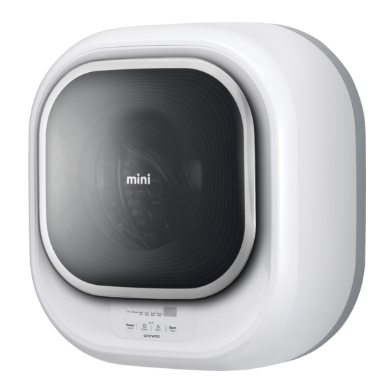
Front-Load Washer MINI
Service Manual
Wall-Mounted
ODW30-999G
DWM30-999PG
Advertisement
Table of Contents

Related Manuals for Daewoo MINI Series


Summary of Contents for Daewoo MINI Series
- Page 1 S/M No. WFWM1_1701 Service Manual Wall-Mounted Front-Load Washer MINI MINI 1.0(WFWM111*) : D-CV701* MINI 1.5(WFWM122*) : ODW30-999B ODW30-999G DWM30-999PG In this Manual, some parts can be changed for improving, their performance without notice in the parts list. So, if you need the latest parts information, please refer to PPL(Parts Price List) in Service Information Center (http://webportal.dwe.co.kr/sic)
-
Page 2: Table Of Contents
Contents 1. What is Wall-Mounted Front-Load Washer MINI? .......... 2 2. Specifications ....................4 3. Assembly Part List .................... 5 4. PCB Functions ....................16 5. Wiring Diagram ....................30 6. Part List and Major Specifications ..............32 7. Installation ....................... 49... -
Page 3: What Is Wall-Mounted Front-Load Washer Mini
1. What is Wall-Mounted Front Load Washer MINI? 1. What is the Wall-Mounted Front-Load Washer MINI? Mini is the world's first ever wall-mounted front-load washer, which is installable in bathroom, pantry, kitchen and various locations. 2. Features of Wall-Mounted Front-Load Washer MINI Spoon-Shaped Detergent Container Containers for detergent and softener are discretely designed to prevent... - Page 4 3. Power Train of Wall-Mounted Front-Load Washer MINI Load Drum Natural drainage Inverter Motor Natural drainage system • Inverter Motor: Transforms electric energy into mechanical energy • Highly powerful and functional inverter motor rotates the system. 4. Major Features of Wall-Mounted Front-Load Washer MINI 1.
-
Page 5: Specifications
2. Specifications 1. Parts and Components Parts TUB REAR BODY DOOR PROTECTOR DOOR HANDLE DOOR FRAME *O COVER BODY AS Parts TUB REAR BODY PROTECTOR GLASS AS DOOR AS COVER BODY AS Category Specifications Notes 550mm X 600mm X 292mm(mini1.0) / Dimension 302mm(mini 1.5) Weight... -
Page 6: Assembly Part List
3. Assembly Part List 1. TUB AS... - Page 7 PART NAME PART CODE DESCRIPTION Q’TY SVC REMARK A01 DRUM SUB AS 3617030010 D-M300 A02 LIFTER WASH 361A401901 D-M300, PP A03 SPIDER AS 361A301610 D-M300 A04 SPECIAL BOLT 3616063000 STS430 M6*21 SI-LOCK 3919601110 DRAIN MOTOR AS NAKAGAW,220-240V-,50/60HZ, BV-DW23 2.5W A05 DRAIN MOTOR AS 66149-0005701-00 BE-3502A, NAKAGAW,220-240V-,50/60HZ, BV-DW23 2.5W DRAIN A06 DRAIN HOUSING...
- Page 8 2. COVER TUB AS PART NAME PART CODE DESCRIPTION Q'TY SCV REMARK CLAMP GASKET AS 3611204540 CLAMP GASKET AS D-M300, D1.4 GAKSET 3612328000 GASKET DOOR D-M300,EPDM PACKING DETERGENT PRPKCA3R90 PACKING DETERGENT D-M300, SILICONE COVER TUB 3618831700 COVER TUB D-M300, FRPP SCREW TAPPING 90007-0002801-00 MFZN F/L T/S-2 5*25 / H GASKET TUB...
- Page 9 3. COVER BODY AS...
- Page 10 PART NAME PART CODE DESCRIPTION Q'TY SVC REMARK D-CV701PCNCX, 361081WG10 COVER BODY SUB AS D-M301 SPRAY D-CV701JCNCX, D-CV701PCNCX COVER BODY SUB AS D-M301 GOLD 361081WG11 D-CV701GCNCX SPRAY COVER BODY MINT BLUE, NO SPRAY, 36113-0026400-00 D-CV701MWNCX CHINA COVER BODY GRAY, IRON SILVER 36113-0026300-00 D-CV701JCNCX SPRAY, CHINA...
- Page 11 4-1. DOOR AS(MINI 1.0: D-CV701*, WFWM11*)
- Page 12 PART NAME PART CODE DESCRIPTION Q'TY SVC REMARK D-CV701PCNCX, D-CV701JCNCX, D-CV701GCNCX, 3612614801 D-M301, ABS, CR-GILDING D-CV701SCNCX, D-CV701TCNCX, D-CV701PCNCX D01 HANDLE DOOR D-CV701MWNCX, 3612614802 D-M301, ABS, SPRAY D-CV701AWNCX 3612614803 D-M301, ABS, SPRAY FOR GOLD D-CV701GGNCX D-CV701, CHINA, 36125-0004004-00 ABS (BG-2501A), D-M300 ODW-JDM883 PIN HANDLE D02 PIN HANDLE...
- Page 13 4-2. DOOR AS(MINI 1.5: ODW30-999B, ODW30-999G, DWM30-999PG, WFWM12*) PART NAME PART CODE DESCRIPTION Q'TY REMARK FRAME DOOR I 36121-0021400-02 PP 419*397*28 1 MINI 1.5 HINGE DOOR 36128-0004400-01 ALDC 2 MINI 1.5 CAP HINGE 3610916500 DOOR TR-PETG HT91-SK GRAY-MASTER DOOR INNER 361A114500 BATCH DWD-M300 HOOK DOOR...
- Page 14 5. BODY AS PART NAME PART CODE DESCRIPTION Q'TY SVC REMARK D-CV701MWNCX, 361081WF10 D-M300 D-CV701AWNCX D-CV701PCNCX, 361081WF11 D-M301 D-CV701JCNCX, D-CV701PCNCX D-CV701GGNCX, 361081WF12 GOLD SPRAY D-CV701GCNCX, B01 BODY AS ODW30-999B 36104-0001806-00 D-M301, SPRAY(GY-7801BP) D-CV701TCNCX 36104-0001807-00 D-M300 (WH-1802A) D-CV701SCNCX 36104-0001809-00 D-M300 SPRAY(WH-1208BP) D-CV701WWNCX 220V, CHINA, Cream White, WH-1404A DWM30-999PG,...
- Page 15 6. PACKING AS PART NAME PART CODE DESCRIPTION Q'TY SVC REMARK CUSHION BOTTOM AS 3611580100 CUSHION BOTTOM AS D-M300 CUSHION CORNER *L 3611578000 CUSHION *L D-M300,EPS CUSHION SHOULDER 36114-0027200-00 EPS 45 MINI 1.5 CUSHION CORNER *R 3611579000 CUSHION *R D-M300,EPS CUSHION SHOULDER 36114-0027200-00 EPS 45 MINI 1.5...
- Page 16 7. Further parts for install <HOOK TYPE> <SCREW TYPE> PART NAME PART CODE DESCRIPTION Q’TY SVC REMARK HOSE INLET 3613270980 DFE04 LLDPE ID=4,OD=6 300M/1Roll HOSE DRAIN *O 3613275839 SVC,D-M300. PE-LD, ID=14,OD=18,L=1M POWER CORD AS 66112-0004303-00 DTIII-2P-05 250V 16A,H05VV-F 3X1.5,5M,EURO See page 46 CONNECTOR 3612512810 UNION CONNECTOR D-M300, AUC0404W 1/4' DMT...
-
Page 17: Pcb Functions
4. PCB Functions 1. Cycle Programs 1.1.1 SEQUENCE CHART (MINI 1.0: D-CV701*, WFWM11*) Program Ver: "q1" Progress Baby Night QUICK INTENSIVE Category Normal Delicate Time Care Time (COLD) Water Supply 2min 47min 15 min 80 min Wash 1 (Heating) 10min 228min 25 min 27min... - Page 18 1.1.2 SEQUENCE CHART (MINI 1.5: ODW30-999B, ODW30-999G, DWM30-999PG, WFWM12*) Program Ver: "u1" NOTE 1. The water temperature is set at 80°C for the steam wash of baby clothes. 2. The speed for the main and middle spin cycles is set at 700RPM except the Delicate 400RPM and 500RPM apply to the Delicate and Night Time cycles, respectively.
- Page 19 1.2. Button Functions Buttons Functional Description Note When the power button is turned off, the power relay is cut offto Power sever the common line for electric supply and, accordingly,ensure electrical safety. 1. MINI 1.0: D-CV701*, WFWM11* Program Ver: "q1" -Premium: Normal->Delicate->Baby Care->Night Time- >QUICK15->Intensive->Intensive40->Intensive60 -Regular: Normal->Delicate->Night Time->QUICK15-...
- Page 20 2. Program Functions 2-1. Wash Program 1) Wash Programs 1 The default washing times and water levels apply for all the programs without sensing the load. 2) Wash Times 1. MINI 1.0: D-CV701*, WFWM11* Category Time of water Water level Heating time Wash time Total wash time...
- Page 21 3) Resupply of Water 1 The water level is measured every two minutes after the initial water supply to add water if the level is lower than the pre-determined level. 2 The motor stops running during the resupply of water. 3 Water is resuppliable up to 20 times during wash.
- Page 22 2-2. Rinse Cycle 1) Drainage 1 If the water is 55°C or hotter, cold water is added to lower the water temperature. When the water temperature decreases to 50°C or lower, water drainage resumes. 2 After the water drainage starts, the drain pump continues to work. 3 If the water level lowers to the reset level within 60 seconds, the waiting time of 20 seconds applies.
- Page 23 3. Functional Structure 3-1. Water Supply Level 1) Water Supply Level 1 RESET : It is the water level to start drainage. The spin cycle starts 30 seconds after the reset level is reached. It is the minimum water level to start operating the heater. 2 HEATER OFF : .
- Page 24 3-2. DOOR S/W 1) DOOR S/W 1 Locking of Door A pulse of 20m sec duty is transmitted twice to the solenoid 3 seconds after the bimetal door switch starts running until the door is locked. The bimetal starts running as soon as the power button is pressed. 2 Unlocking of Door A pulse of 20m sec duty is transmitted to the solenoid after the bimetal door switch is turned off until the door is unlocked...
- Page 25 4. TEST MODE 4-1. Part Test Mode 1) Test Start 1 Press the 'Program' button and then select 'Delicate' program. With the 'Program' button pressed, press the 'Add Rinse' button three times to start a test. 2 The product version is displayed after starting a test. 3 Press the 'Program' button to run the washer in the following sequence.
- Page 26 5. Error Alerts 5-1. IE (Input Error) Error - Failure in Water Supply 1) Conditions 1 The preset water level is not reached within 20 minutes after the water supply starts or resumes. 2 During wash: The error occurs 4 minutes after the water level remains unchanged or 20 minutes after the water level starts changing.
- Page 27 5-4. E1 Error - Error in Water Level Detection 1) Conditions 1 The water level is below the reset level or above the overflow level in the line test mode. 2) The drainage synchronous motor continues to work until the water level drops to the reset level. 3) If the Power button is turned off and on, the error display disappears.
- Page 28 5-7. E4 Error - Error in the Detection of Water Leaks 1) Water is resupplied over 20 times during a wash cycle. -> This rarely occurs due to the short cycle duration. 2) The motor stops running and the 'E4' error appears on the display panel. 3) If the Power button is turned off and on, the error display disappears.
- Page 29 5-10. Errors in Temperature Sensor (Available for premium model only) 1) H2 Error - Open/Short error in washer temperature sensor (Available for premium model only) 1 The washer temperature sensor fails to work or is not properly connected. 2 The error warning is sounded for 10 seconds every 10 minutes. 3 If the Power button is turned off and on, the error display disappears.
- Page 30 6. PCB PIN 1. MINI 1.0: D-CV701*, WFWM11* ① FW1(WHITE 8PIN) ② WF9(BLACK 4PIN) 1: COLD V/V 1: Vdd 2: SOFT V/V 2: GND 3: DRAIN V/V 3: LEVEL SENSOR 4: LOCK-PTC 4: W-TEMP 5: LOCK-SOL 7: DRAIN-CHECK 8: LOCK-CHECK ③...
-
Page 31: Wiring Diagram
5. Wiring Diagram D-CV701****01 D-CV701****... - Page 32 MINI 1.5: ODW30-999B, ODW30-999G, DWM30-999PG, WFWM12*...
-
Page 33: Part List And Major Specifications
6. Part List and Major Specifications PART NAME PART CODE SPEC MAKER REMARK DWD200BL, DC 310 V, 125 W, Wash Motor 36189L8000 New Motec Class F GJ-2BA003A, DC 310 V, 125 W, Wash Motor 36189L8500 G&J Class F Tonlon Motor Tonlon BV-DW23, 220-240 V, 2.5 W, Class Gyeong Nam... - Page 34 PART NAME PART CODE SPEC MAKER REMARK Relay 5SC0101250 SJ-S-112DM, 250V, 10A SANYOU MINI1.0 40512-0017800, Input : DC 310 V, Transformer 40512-0017800-00 MINI 1.5 output : DC 5 V, 15 V, Class E Transformer 5EM102806C 220-240V~ 50/60Hz Namseong Electric MINI1.0 SamHwa Varistor 40D09-0000700-00...
- Page 35 1. Specifications, Operation, and Defect Inspection of Inverter Motor 1) Specifications Category Specifications Configuration Motor Type Ternary Phase Brushless DC Motor Ventilation/Cooling Open/magnetic ventilation For Use Load Front load washer Stator Pole 9 POLE Rotor Pole 6 POLE Voltage (V) DC 240 - 310V Max.
- Page 36 □ Motor's Functional Mechanism - The device transforms electric energy into mechanical energy. - The motor contains a costly auxiliary driving gear, is controlled by semiconductors, causes low electric/ mechanical noises, and is capable of running at high speed. - The hall IC applies to locate the rotor. It acts as a brush-type commutator. - The hall IC locates the active rotor with the magnet attached to the rotor and sends signals from the current rotor location to the base of transistor connected to the coil producing torques.
- Page 37 2. Specifications, Operation, and Defect Inspection of Drain Motor 1) Specifications Category Specifications Configuration Type Combination of Housing and Synchronous Motor Pole Negative Pole Synchronous Motor Revolution per Minute 5/6R.P.M. (50/60Hz) Electric Current 35mA or lower Power Consumption 3.0W or lower Voltage AC220~240V, 50/60Hz Opening of Bellows...
- Page 38 ☞ Set Operation ▷ When the drainage valve is on When the internal switch is off, signals continue to be transmitted to the drain motor until the internal switch is turned on. If the internal switch is turned on, signals are sent to the drain motor for about 3.6 seconds, which is subsequently turned off.
- Page 39 4) In the event of OE after remdy, follow the below directions. Inspection method: Remove the join area around "100mm" from the hose drain. After removal, clean the area where the foreign object was located . Clean the area (100mm) HOSE DRAIN * O 5) Cleaning and Exchange of Drain Housing STOPPER...
- Page 40 3. Specifications, Operation, and Defect Inspection of Inlet Valve [Valve for cold water and softener] 1) Specification Category Specifications Configuration Type 1/4 Inch Fitting Solenoid Valve Voltage AC 220 VOLT 50/6Ohz Electric Current 30mA or lower #250 Red color (Water inlet) Rating Time 60 minutes (Unloaded = 40 minutes) Power Consumption...
- Page 41 3) Inspection and Repairs of Water Inlet Valve PCB Error Defects Descriptions Causes Inpsection Method Repair Method Mode Water supply Water is not Faucet is turned off. Check whether the faucet is turned on Turn on the faucet "IE" unavailable supplied despite Short coil Check whether the inter-terminal...
- Page 42 5) Disassembly and Asssembly for Part Exchange [Disassembly] 1 Turn off the faucet 2 Detach the housing 3 With the snap fit on inlet (red) pressed, separate the inlet hose. With the snap fit on outlet (gray) pressed, separate the inlet hose. 4 Unscrew a bolt * Notes 1 Connect the inlet hose properly to the inlet (red) and outlet (gray)
- Page 43 4. Specifications, Defect Inspection, and Repairs of Heater 1) Specifications Category Specifications Note 1. Temperature Fuse of Water Heater (184 °C Cutoff Maker 1RCA Type) Voltage 220V • If the heater is running without water due to a Power Consumption 1400 W ±5% malfunction in water level sensor and other Resistance...
- Page 44 2) Defect Inspection Defects and PCB Error Causes Inspection of Defects and Errors Resolution Errors Mode Water is not Wire Inspect the wire connection: Reconnect the "H6" heated disconnection Applicable to all models disconnection (Applicable Disconnection in Inspect the wire connection: If the Exchange the "H6"...
- Page 45 5. Specifications, Operation, and Defect Inspection of Water Level Sensor 1) Specifications RESET: O/F: Water level at which the water must be drained 1. Drainage level. A spin cycle starts 20 to 40 due to excessively high level. Water supply is seconds after the reset level is reached.
- Page 46 2) Defect Inspection Defects Inspection of Defects PCB Error Details Causes Resolution and Errors and Errors Mode Incessant Water Defect in the bellows Check the frequency Exchange the "E2" water continues to of water level sensor water level sensor supply be supplied Defect in pressure Check the frequency...
- Page 47 6. Specifications, Operation, and Defect Inspection of Door Lock Switch 1) Specifications of Door Lock Switch TYPE Part Code Model Power Locking Mechanism DF F01 007 36169047230 DWD-M301WP 250V 16A Bimetal operation on the PTC heat DWD-M300WA Lock "On/Off" Time Lock Off Type Configuration 1.
- Page 48 Defects and Inspection of Defects and Error Details Causes Resolution Errors Errors Mode Non- Power cutoff or After the "power cutoff" or "forced shutdown" during operation, openable forced shutdown "PCB MICOM" is not able to open the door. At least 5 minutes Door during operation must pass before the door becomes openable.
- Page 49 7. Specifications and Assembly of Cord Power Assy 1) Specifications PART CODE COUNTRY COMPANY cord power (3m) cord power (5m) cord power as(3m) cord power as(5m) 3611340450 3611340470 3611340460 3611340480 USA, MEXICO LONGWELL WHITE 125V 13A,SJT 16AWG 3C UL,MEXICO/COLOMBIA 3611340240 3611340260 3611340250 3611340280...
-
Page 50: Installation
7. Installation Follow the installation guide to install the washing machine more conveniently. Do not plug in the power cord when installing. Before installation After installation Make sure to perform a test run to check for any water leakage or abnormal noise. 7-1. - Page 51 9. I n j e ct chemi c al anchor and i n sert cushi o n pads 10. Install the washing machine. 11. Organize hoses - I n j e ct chemi c al anchors i n to the fi x ed set anchors - I n stal l the washi n g machi n e sti c k to the wal l - Organi z e and pl a ce hoses i n the hol e .
- Page 52 15. Organi z e the i n l e t and drai n hoses and power cord 16. Mount the Body - Organi z e the i n l e t and drai n hoses usi n g mol d i n g - Connect the 4 upper and l o wer bol t s after and hose gui d e.
- Page 53 7-2. WHEN THE MACHINE CANNOT BE INSTALLED WITH BASIC INSTALLATION MATERIALS. 1. Determine installation location 2. Inspect the wall 3. Attach the installation manual - determi n e the i n stal l a ti o n si t e, consi d eri n g the - Knock on the wal l to check i f the wal l i s concrete.
- Page 54 9. Insert the cushion pad 10. Install the washing machine. 11. Organize hoses - Attach pads on the fi x ed anchors. - I n stal l the washi n g machi n e sti c k to the wal l - Organi z e and pl a ce hoses i n the hol e .
- Page 55 15. Organize the inlet and drain hoses and power cord 16. Mount the Body - Organi z e the i n l e t and drai n hoses usi n g mol d i n g and hose gui d e. - Connect 4 upper and l o wer bol t s after mounti n g the body.
- Page 56 7-3 WHEN IT CANNOT BE INSTALLED ACCORDING TO THE TWO INSTRUCTIONS ABOVE. 1. Drill a hole into the retaining 2. Clean the drilled area with 3. Inject the chemical into the wall wall. compressed air and a brush. and fix the anchor. - Set the hammer drill or a drill perpendicular - Clean the drilled hole at least 3 times with - Insert a plastic net and inject the chemical.
-
Page 58: About This Manual
ABOUT THIS MANUAL (주) 신광씨링 광주광역시 서구 하남대로 502번길 14 담 당 김현규 님 MINI 1.0(WFWM111*) : D-CV701* MINI 1.5(WFWM122*) : ODW30-999B, ODW30-999G, DWM30-999PG M O D E L 영문 _ Service Manual 접 수 2017.02.02 M E M O 총...
Need help?
Do you have a question about the MINI Series and is the answer not in the manual?
Questions and answers