Table of Contents
Advertisement
Quick Links
Advertisement
Table of Contents

Related Manuals for ABB NIBA-01


Summary of Contents for ABB NIBA-01
- Page 1 ABB Drives Installation and Start-up Guide InterBus-S Adapter Module NIBA-01...
- Page 3 InterBus-S Adapter Module NIBA-01 Installation and Start-up Guide 3AFY 58919811 R0125 EFFECTIVE: 1998-04-01 SUPERSEDES: NONE © 1998 ABB Industry Oy. All Rights Reserved.
- Page 4 NIBA-01 Installation and Start-up Guide...
-
Page 5: Safety Instructions
Safety Instructions Overview This chapter states the safety instructions that must be followed when installing and operating the NIBA-01 InterBus-S Adapter Module. The material in this chapter must be studied before attempting any work on, or with, the unit. Warnings and Notes This manual distinguishes two sorts of safety instructions. - Page 6 These functions should not be selected if other equipment is not compatible with this kind of operation, or dangerous situations can be caused by such action. More Warnings and Notes are printed at appropriate instances along the text. NIBA-01 Installation and Start-up Guide...
-
Page 7: Table Of Contents
The NIBA-01 InterBus-S Adapter Module ........ - Page 8 PCP Services Supported by NIBA-01 ........
-
Page 9: Chapter 1 - Introduction To This Guide
The Guide is intended for the people who are responsible for installing, commissioning, and using the NIBA-01 InterBus-S Adapter Module with an ABB drive. The reader is expected to have a basic knowledge • electrical fundamentals and wiring practices • the drive and its control panel •... -
Page 10: Conventions Used In This Guide
Refers to the InterBus-S master station, i.e. a PLC or a computer controlling the bus through an InterBus-S interface. NIBA-01 InterBus-S The NIBA-01 Adapter Module is one of the optional fieldbus adapter Adapter Module modules available for ABB drives. The NIBA-01 is a device through which an ABB drive is connected to an InterBus-S serial communication bus system. -
Page 11: Chapter 2 - Overview
Chapter 2 – Overview Overview This chapter contains a short description of the InterBus-S system and the NIBA-01 Adapter Module, a delivery checklist, and warranty information. The InterBus-S InterBus-S is an open serial communication standard for the sensor– actuator level. The protocol is based on DIN 19245 Part 2 and itself System specified in DIN 19258. -
Page 12: Data Channels
PCP channel (for acyclic transfer of non-time-critical, complex blocks of data, e.g. parameter data). The NIBA-01 The NIBA-01 InterBus-S Adapter Module is an optional device that enables connection of an ABB drive to an InterBus-S system. The InterBus-S Adapter module is considered a remote bus device by the host. -
Page 13: Compatibility
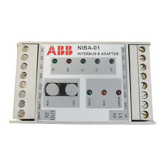
Chapter 2 – Overview Status LEDs There are eight status LEDs on the NIBA-01 Module. The table below explains their functions. Operation Explanation DDCS flashing DDCS initialisation in progress flashing, ERROR lit DDCS communication errors DDCS communication established IB-S flashing (fast) -
Page 14: Delivery Check
18 months, from the date of delivery. Extended warranty may be available with certified start-up. Contact your local distributor for details. Your local ABB Drives company or distributor may have a different war- ranty period, which is specified in their sales terms, conditions, and warranty terms. -
Page 15: Chapter 3 - Mechanical Installation
2. Fasten the rail and ensure the proper earthing as described above. 3. Push the module onto the rail. The module can be released by pulling the locking spring with a screwdriver (see Figure 3-1). Earthing Clips Figure 3-1 Mounting and removing the module. NIBA-01 Installation and Start-up Guide... -
Page 16: Mounting Inside The Drive
Observe the free space requirements for the module (min. 10 mm from adjoining equipment/wall). 7. Push the module onto the rail. The module can be released by pulling the locking spring with a screwdriver (see Figure 3-1). NIBA-01 Installation and Start-up Guide... -
Page 17: Chapter 4 - Electrical Installation
The maximum long term tensile load for the fibre optic cable is 1 N. The minimum short term bend radius is 25 mm. The NIBA-01 module is connected to the drive using a fibre optic cable link. Consult the drive documentation as to the corresponding terminals inside the drive. -
Page 18: Module Earthing
X1 on the NIBA-01. The outgoing bus cable (if required) is connected to X2. See the connection diagram on page 4-4. Note: If the NIBA-01 module is the last station on the remote bus, the terminals of X2 are left unconnected. - Page 19 (Not connected if the module is the last device on the remote bus.) X2 (OUT) Description Shield (Module earth) Data in 2 /DI2 Data in 2 (Inverted) Data out 2 /DO2 Data out 2 (Inverted) Signal Ground RBST Remote Bus Connector RB5V Signal +5V NIBA-01 Installation and Start-up Guide...
- Page 20 /DI2 +24V DDCS IB-S ERROR +24V /DI1 /DO1 DO1 RB5V RBST DG2 /DO2 DO2 /DI2 +24V DDCS IB-S REMOTE BUS ERROR +24V /DI1 /DO1 DO1 Male DSUB Connector Figure 4-2 InterBus-S remote bus cable connections. NIBA-01 Installation and Start-up Guide...
-
Page 21: Chapter 5 - Programming
This chapter gives information on configuring the drive and the InterBus-S system for communication through the NIBA-01 Module. It is assumed that the NIBA-01 has been mechanically and electrically installed according to the instructions given in Chapters 3 and 4. -
Page 22: Control Locations
IB TIME-OUT If the communication between the NIBA-01 and the host fails, this parameter defines the time after which the NIBA-01 stops communicating with the drive. (See the drive manuals for information on drive behaviour if this occurs.) Setting the parameter to 0 disables... -
Page 23: Host Configuration
The need for further configuration depends on the host controller software and the application. The configuration data in Table 5-2 below is valid for the NIBA-01. Table 5-2 Host controller configuration data for the NIBA-01 module. Communication Parameter Value... -
Page 24: Calculating The Optimal Cycle (Scan) Time
Software runtime (0.2 ms) Runtime on the transmission medium (for copper, 0.016 ms l/km, • where l = remote bus cable length in kilometres) Note: The minimum cycle time with the NIBA-01 is 1 ms. NIBA-01 Installation and Start-up Guide... -
Page 25: Chapter 6 - Communication
DATA SET 2 DATA WORD 3 (DW 2.3) PCP CHANNEL* ACTUAL VALUE 1 (ACT1) ACTUAL VALUE 2 (ACT2) STATUS WORD (SW) *USED IN PCP MODE ONLY. SEE PCP SERVICES SUPPORTED BY NIBA-01 BELOW. Figure 6-1 InterBus-S message frame. NIBA-01 Installation and Start-up Guide... -
Page 26: Pcp Services Supported By Niba-01
(in hexadecimal) Invoke ID: For NIBA-01, 00 Comm.Ref.: The Communication Reference (module number) assigned for the NIBA-01 upon host configuration (in hexadecimal) Password: For NIBA-01, 00 Index: ((Drive Param. No.) • 100 + 12288), converted to hexadecimal Subindex: For NIBA-01, 00... - Page 27 Chapter 6 – Communication Read Reads a parameter value from the drive via NIBA-01. Read Request: Example of a Read Request (Param. 30.19): BYTE 1 BYTE 2 BYTE 1 BYTE 2 Command Code (0081h) Parameter Count Invoke ID Comm.Ref. eg. 02...
- Page 28 Chapter 6 – Communication Write Writes a parameter value to the drive via NIBA-01. Example of a Write Request (Param. 21.02 set to 1000): Write Request: BYTE 1 BYTE 2 BYTE 1 BYTE 2 Command Code (0082h) Parameter Count Invoke ID Comm.Ref.
- Page 29 Error Class Phys. Status Length Error Code Add. Code String of Local Add. Code Detail Logical Status: 1 = Limited number of services 0 = Ready to communicate Physical Status: 0 = Ready for operation NIBA-01 Installation and Start-up Guide...
- Page 30 Error Code Add. Code Str. of Vendor Add. Code Length Str. of Module String of Module Length Str. of Rev. String of Revision Vendor: ABB Industry Oy Model: NIBA-01 Revision: Rev. SW x.x HW x NIBA-01 Installation and Start-up Guide...
- Page 31 Parameter Count Parameter Count Invoke ID Comm.Ref. Invoke ID Comm.Ref. Result (+) More-Follows Result (–) Error Class Length List of O.D. Error Code Add. Code List of Object Description Add. Code List of Object Description NIBA-01 Installation and Start-up Guide...
- Page 32 Chapter 6 – Communication Initiate Initiates communication between the InterBus-S host and the NIBA-01. Initiate Request: Example of an Initiate Request: BYTE 1 BYTE 2 BYTE 1 BYTE 2 Command Code (008Bh) Parameter Count Invoke ID Comm.Ref. eg. 02 Password...
- Page 33 Chapter 6 – Communication Abort Aborts the connection between the host and the NIBA-01. Abort Request: Abort Indication: BYTE 1 BYTE 2 BYTE 1 BYTE 2 Command Code (008Dh) Message Code (01ADh) Parameter Count Parameter Count – Comm.Ref. – Comm.Ref.
-
Page 34: The Control Word And The Status Word
The contents of both the Control and Status Words are explained in the drive documentation. The Control and Status Words are not altered by the NIBA-01 in any way, excepting Bit 15 of the Status Word, which is turned on by the module in case of an error in the DDCS communication between the module and the drive. -
Page 35: Appendix A - Definitions And Abbreviations
Error location. (Local station: 00; Remote station: FF) Log. Status Status of the module program Object Dictionary Local storage of all Communication Objects recognised by a device Original Invoke ID Invoke ID of the service which caused a reject NIBA-01 Installation and Start-up Guide... - Page 36 Appendix A – Definitions and Abbreviations See Object Dictionary Password Password for the access control Peripherals Communication Protocol. Also, an operating mode of the NIBA-01 for transferring parameter data Phys. Status Status of the module hardware Primitive Basic operation of a service...
-
Page 37: Appendix B - Technical Data
Appendix B – Technical Data DDCS Link Compatible Devices: All ABB Fieldbus Adapter modules, ABB ACS 300, ACS 600 SingleDrive, ACS 600 MultiDrive, ACS 600 MotionControl, ACF 600 Pump & Fan Drive, DCS 500 Size of the Link: 2 stations Medium: Fibre optic cable •... -
Page 38: Interbus-S
Maximum No. of Remote Bus Segments: 32 Maximum No. of Remote I/O Stations: 256 Medium: RS-485 cable, 3 x 2 (twisted pairs), common shield Serial Communication Type: Asynchronous, full duplex Transfer Rate: 500 kBit/s Minimum Bus Cycle (Scan) Time: 1 ms NIBA-01 Installation and Start-up Guide... -
Page 39: Niba-01
Get-OV, Read, Write Maximum PDU Length 64 bytes COMMUNICATION REFERENCE LIST ENTRIES Max-PDU Sending-High-Prio Max-PDU Sending-Low-Prio 64 bytes Max-PDU Receiving-High-Prio Max-PDU Receiving-Low-Prio 64 bytes PMS-Services-Supported 80 30 00 / 00 00 00; Client / Server NIBA-01 Installation and Start-up Guide... - Page 40 Data in 2 (Inverted) Data out 2 /DO2 Data out 2 (Inverted) Signal Ground RBST Remote Bus Connector RB5V Signal +5V General: • All materials are UL/CSA approved • Complies with EMC Standards EN 50081-2 and EN 50082-2 NIBA-01 Installation and Start-up Guide...
-
Page 41: Appendix C - Ambient Conditions
Chemical gases: IEC 721-3-3, Class 3C2 Solid particles: IEC 721-3-3, Class 3S2 Installation Site Altitude: 0 to 2000 m. If installation site is above 2000 m, contact local ABB representative. Vibration: Max 0.3 mm (2 to 9 Hz), max 1 m/s (9 to 200 Hz) - Page 42 Appendix C – Ambient Conditions NIBA-01 Installation and Start-up Guide...
- Page 44 ABB Industry Oy Drives Group P.O.Box 184 FIN-00381 Helsinki FINLAND Telephone: +358 10 222 000 Telefax: +358 10 222 2681...