
Related Manuals for Baxi PREMIER PLUS Series


Summary of Contents for Baxi PREMIER PLUS Series
- Page 1 PREMIER PLUS INSTALLATION AND USER INSTRUCTIONS 400L, 500L & 570L Indirect Russian Version on Page 17...
-
Page 2: Important Installation Points
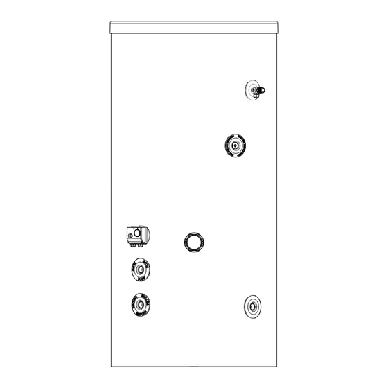
- How hot water can be drained. (see page 11 for details). 1. IMPORTANT INSTALLATION POINTS 1.1 The BAXI Premier Plus water heater MUST be fitted with a pressure relief valve rated at 8 bar. FAILURE TO PROVIDE ADEQUATE PRESSURE RELIEF WILL INVALIDATE ANY GUARANTEE AND LEAD TO A DANGEROUS INSTALLATION. - Page 3 Diagram 1 - Dimensions HOT OUTLET T&P VALVE SECONDARY RETURN THERMOSTATIC CONTROL (BOILER) 3kW IMMERSION PRIMARY FLOW PRIMARY RETURN COLD INLET DIMENSIONS (mm) SIZE 400L 1502 500L 1802 1132 570L 1336 1997 Table 1: Dimensions...
- Page 4 Max direct kW rating Coil surface area (m²) 15l/min Coil heat up times 30l/min (Mins) 60/min 15l/min 28.2 27.6 27.0 Coil rating (kW) ² 30l/min 41.9 40.0 39.1 60l/min 56.9 54.3 53.6 15l/min 0.02 Pressure drop through 30l/min 0.04 coil (MPa) 60l/min 0.32 Heat loss (kW/24hrs)
-
Page 5: Installation - Plumbing
3. INSTALLATION – PLUMBING 3.1 Refer to section IMPORTANT INSTALLATION POINTS. Plumb in valves in the sequence shown in diagram 3, below. Ensure the valves are installed in the correct orientation by reference to the direction of flow arrows marked on them. 3.2 The water connections on the water heater accept direct connection of 1”... -
Page 6: Electrical Requirements
Drain valve 4. ELECTRICAL REQUIREMENTS 4.1 The BAXI Premier Plus water heater is suitable for use with most gas or oil fired boilers provided the boiler has adequate thermostatic control and over-temperature protection. If in doubt consult the boiler manufacturer. - Page 7 Diagram 5 Control High limit thermostat thermostat Load (Demand Contact) Satis ed Common (S/L) Diagram 6 Temperature Adjustment Thermal cut-out °C reset under screw head Diagram 7 INDIRECT THERMOSTAT 2 PORT ZONE VALVE PROGRAMMER DHW HEAT EXCHANGER AND THERMAL CUT-OUT Ph N 2 x 2 PORT ZONE VALVE SYSTEM...
- Page 8 Diagram 8 INDIRECT THERMOSTAT PROGRAMMER AND THERMAL CUT-OUT Ph N 3 PORT MID POSITION VALVE SYSTEM WIRING CENTRE ELECTRICAL SUPPLY NOTE: THE EARTH CONNECTIONS HAVE BEEN OMITTED FOR CLARITY. ALL EARTH CONNECTIONS MUST BE LINKED BACK TO THE EARTH TERMINALS IN THE WIRING CENTRE CV PUMP 3 PORT MID POSITION...
- Page 9 5. IMMERSION HEATER - ELECTRICAL REQUIREMENTS Note: At the time of installation the Cylinder is fitted with a blank immersion boss and cover. A 3kW immersion is available as an accessory, 95 602 030, page 14 5.1 If the water heater is fitted with a supplementary immersion heater it will incorporate a thermostatic control and over-temperature cut-out.
- Page 10 Diagram 10 Thermostat Earth Post Brown Blue Fused (13A) double pole isolating switch 1.5mm² 3 core HOFR sheathed cable 230V ~ MONOPHASE Diagram 11 Customer earthing Thermal cut-out terminal reset button Temperature adjustment Thermostat...
- Page 11 6. COMMISSIONING 6.1 DO NOT switch on either the immersion heater or boiler until the water heater has been filled with water and checked for leaks. 6.2 Check that all installation, electrical and discharge pipe requirements have been met. 6.3 Check that all water and electrical connections are correctly made and are tight. 6.4 Open a hot tap supplied by the water heater, turn on the cold water supply to the water heater.
- Page 12 7.9 Replace the immersion heater thermostat by carefully plugging the two male spade terminations on the underside of the thermostat head into the corresponding terminations on the element. Ensure the thermostat is pushed fully home. 7.10 Rewire the immersion heater in accordance with diagram 10, page 9. Refit and secure the terminal cover.
-
Page 13: User Instructions
NOTE the water discharged may be very hot. Ensure the valve re-seats correctly when released. 10. USER INSTRUCTIONS 10.1 The BAXI Premier Plus water heater stores water at the temperature set on the adjustable thermostat. This is factory set to give a storage temperature of approx. 60 C. However, this can be... -
Page 14: Spare Parts
12. SPARE PARTS 12.1 The following list of spare parts is available for the BAXI Premier Plus water heater. Refer to the technical data label on the water heater to identify the model installed and to ensure the correct parts are ordered. - Page 15 Notes: The pace of product development is such that we reserve the right to change product specifications without notice. We do, however, strive to ensure that all information in this leaflet is accurate at the time of publication.
- Page 16 Baxi Heating UK Ltd - Heatrae Sadia Heating Trading Division Hurricane Way Norwich NR6 6EA England www.heatraesadia.com A BDR Thermea company 36006191_issue_04...
Need help?
Do you have a question about the PREMIER PLUS Series and is the answer not in the manual?
Questions and answers