Table of Contents
Advertisement
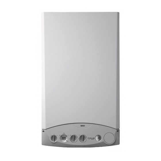
Wall-mounted condensing boilers
PRIME HT
Installerʼs and Userʼs Instructions
GB
0085
BAXI S.p.A. is a leading European manufacturer of central heating and domestic hot water appliances (wall mounted gas
boilers, floor standing boilers, electric water heaters) and has been certified by CSQ as conforming to UNI EN ISO 9001.
This certification confirms that the Quality System of BAXI S.p.A. in Bassano del Grappa, where this boiler was manufactured,
satisfies the strict UNI EN ISO 9001 standard covering all aspects of company organisation, manufacturing and distribution.
CERTIFICAZIONE DEI SISTEMI
QUALITA' DELLE AZIENDE
UNI EN ISO 9001
Advertisement
Table of Contents

Related Manuals for Baxi PRIME HT 240


Summary of Contents for Baxi PRIME HT 240
- Page 1 floor standing boilers, electric water heaters) and has been certified by CSQ as conforming to UNI EN ISO 9001. This certification confirms that the Quality System of BAXI S.p.A. in Bassano del Grappa, where this boiler was manufactured, satisfies the strict UNI EN ISO 9001 standard covering all aspects of company organisation, manufacturing and distribution.
- Page 2 Do not leave any parts of the packaging (plastic bags, polystyrene, etc.) within children’s reach as they are a potential source of danger. BAXI boilers bear the CE mark in compliance with the basic requirements as laid down in the following Directives:...
-
Page 3: Table Of Contents
CONTENTS INSTRUCTIONS PERTAINING TO THE USER Instructions prior to installation Instructions prior to commissioning Commissioning of the boiler Filling the boiler Switching the boiler off Prolonged standstill of the system. Frost protection Gas change Servicing instructions INSTRUCTIONS PERTAINING TO THE INSTALLER General information 10. -
Page 4: Instructions Prior To Installation
1. INSTRUCTIONS PRIOR TO INSTALLATION This boiler is designed to heat water at a lower than boiling temperature at atmospheric pressure. The boiler must be connected to a central heating system and to a domestic hot water supply system in compliance with its performances and output power. -
Page 5: Instructions Prior To Commissioning
2. INSTRUCTIONS PRIOR TO COMMISSIONING Initial lighting of the boiler must be carried out by a licensed technician. Ensure the following operations are carried out: a) compliance of boiler parameters with (electricity, water, gas) supply systems settings. b) compliance of installation with the laws and regulations in force. c) appropriate connection to the power supply and grounding of the appliance. - Page 6 3.1 ADJUSTING ROOM TEMPERATURE The central heating system must be equipped with a thermostat to control room temperature. If no room temperature thermostat is installed when the boiler is first started up, room temperature can be controlled using the control knob (6). Simply turn the control knob clockwise to increase room temperature or anti-clockwise to decrease it.
-
Page 7: Filling The Boiler
3.3.1 TABLE OF FAULTS AND ERROR MESSAGES Error Description of fault Corrective action code Outdoor temperature sensor fault Call an authorised service centre. Central heating NTC sensor fault Call an authorised service centre. Flue NTC sensor fault Call an authorised service centre. Domestic hot water NTC sensor fault Call an authorised service centre. -
Page 8: Switching The Boiler Off
PRIME HT 240 - HT 280 - HT 330 PRIME HT 1.120 - HT 1.240 - HT 1.280 Boiler filling cock Boiler filling cock Boiler drain cock Figure 4a Figure 4b The boiler is equipped with a water pressure switch that prevents the boiler from starting up if there is no water in the system. -
Page 9: General Information
9. GENERAL INFORMATION The following remarks and instructions are addressed to Service Engineers to help them carry out a faultless installation. Instructions regarding lighting and operation of the boiler are contained in the ‘Instructions pertaining to the user’ section. Note that installation, maintenance and operation of the domestic gas appliances must be performed exclusively by qua- lified personnel in compliance with current standards. -
Page 10: Boiler Installation
11. BOILER INSTALLATION Decide upon the boiler location, then tape the template on the wall. Connect the pipework to the gas and water inlets prearranged on the template lower bar. If you are either installing the boiler on a pre-existent system or substituting it, we suggest you also fit settling tanks on the system return pipework and under the boiler to collect the deposits and scaling which may remain and be circulated in the system after the purge. -
Page 11: Fittings Present In The Packaging
By means of a splitting kit a two-pipe system may also be installed. In case exhaust and intake flues not supplied by BAXI S.p.A. have been installed, these must be certified for the type of use and must have a maximum pressure drop of 100 Pa. - Page 12 Flue duct terminal Max. length Each 90° bend Each 45° bend Flue Outer of flue duct reduces the duct reduces the duct terminal terminal max. length by max. length by diameter diameter Coaxial Ø 60/100 mm 10 m 0,5 m 100 mm 100 mm Vertical two-pipe...
- Page 13 VERTICAL FLUE TERMINAL Ø 60/100 MM INSTALLATION OPTIONS This type of installation can be carried out both on a flat or pitched roof by fitting a terminal, an appropriate weathering tile and sleeve, (supplementary fittings supplied on demand). L max = 10 m L max = 10 m L max = 8 m L max = 9 m...
- Page 14 Figure 11 A 90° bend reduces the total duct length by 0.5 metre. A 45° bend reduces the total duct length by 0.25 metre. SEPARATED HORIZONTAL FLUE TERMINALS INSTALLATION OPTIONS IMPORTANT: Ensure a minimum downward slope of 1 cm toward the boiler per each metre of duct length. Make sure that the exhaust and intake ducts are securely fixed to the walls.
-
Page 15: Connecting The Mains Supply
SEPARATED VERTICAL FLUE TERMINALS INSTALLATION OPTIONS L max = 14 m L max = 15 m Important: if fitting a single exhaust flue duct, ensure it is adequately insulated (e.g.: with glass wool) wherever the duct passes through building walls. For detailed instructions concerning the installation of fittings refer to the technical data accompanying the fittings. - Page 16 15.1 DESCRIPTION OF THE ELECTRICAL CONNECTIONS TO THE BOILER Turn the control box downward to access terminal boards M1 and M2 used for the electrical connections by removing the two protective covers (see figure 12). Terminals 1-2, terminal board M1: room temperature thermostat “TA”. Terminals 4-5, terminal board M2: connections for the optional SIEMENS QAA73 temperature regulator.
- Page 17 QAA73: parameters which can be set by the installer (service) By pressing the two PROG buttons together for at least three seconds it is possible to access the list of parameters that the installer can display and/or set. Press either of these buttons to change the parameter to display or change. Press the [+] or [-] key to change the value displayed.
- Page 18 - fault messages In the event of fault, the display panel on the QAA73 shows the flashing symbol . Press the information key ( ) to display the error code and a description of the fault. Code Display Fault description Outsidesense Outdoor temperature probe sensor fault (or parameter 75 disabled) Boilersensor...
- Page 19 Graph 1 Graph 2 TM = Flow temperature Te = Composite outside temperature b) with QAA73 temperature regulator: The temperature curve “kt” must be selected by setting parameter 70 “HC1 gradient” of the QAA73 temperature control device as described in section 15.2 “QAA73: parameters which can be set by the installation engineer (service)”. See graph 3 for selecting the curve referred to a room temperature of 20°C.
- Page 20 15.4 ELECTRICAL CONNECTIONS TO A MULTI-ZONE SYSTEM The electrical connections and settings needed to control a multi-zone central heating system vary depending on what accessories are connected to the boiler. To permit the boiler to handle requests from individual zones, turn the Summer/Winter selector (1 - figure 1) on the boiler’s front panel to Winter ( ) position.
- Page 21 15.5 CONNECTING AN EXTERNAL BOILER (FOR MODELS PRIME HT 1.120 – 1.240 – 1.280) Boiler models PRIME HT 1.120 – 1.240 – 1.280 feature a three way power valve for connecting an external boiler. Connect the boiler water pipes as shown in figure 16. Remove the resistor from terminals 9-10 of terminal board M2, and connect the optional DHW priority sensor to them (figure 16).
-
Page 22: Changing Gas Type
16. CHANGING GAS TYPE Proceed as follows to calibrate the gas valve. 1) Calibrate maximum thermal power. With the boiler operating at maximum thermal power, check that the value for CO measured in the flue corresponds to that specified in table 1 (a-b-c). If necessary, turn the adjuster screw (V) on the gas valve. - Page 23 Figure 18A Figure 18B ~ 5 seconds Figure 19 0402_2513 ~ 5 seconds Figure 20 0402_2514 INSTRUCTIONS FOR THE INSTALLER...
- Page 24 8,4% 9,8% Gas nozzle 12,0 mm 12,0 mm Table 1a PRIME HT 1.240 PRIME HT 240 G20 - 2H - 20 mbar G31 - 3P - 37 mbar PRIME HT 280 max. heat output 8,7% min. heat output 8,4%...
-
Page 25: Displaying Electronic Control Card Parameters On The Boiler Display ("Info" Mode)
PRIME HT 240 - HT 1.240 Gas consumption at 15 °C G20 - 2H - 20 mbar G31 - 3P - 37 mbar 1013 mbar 34.02 MJ/m 46.3 MJ/kg Consumption at max. heat output 2.61 m 1.92 kg/h Consumption at min. heat output 0.74 m... - Page 26 Turn the control knob 7 to display the values of the following parameters in sequence: A0: domestic hot water output temperature (in °C); A1: outdoor temperature (in °C); A2: the value (%) of the PWM signal to the fan (reserved for service engineers); A3: fan speed (in rpm) x 100 (reserved for service engineers);...
-
Page 27: Control And Operation Devices
18. CONTROL AND OPERATION DEVICES The boiler has been designed in full compliance with European reference standards and in particular is equipped with the following • Safety thermostat This device uses a sensor on the central heating delivery line to cut off the flow of gas to the burner if the water in the primary circuit overheats. -
Page 28: Positioning Of The Ignition And Flame Sensing Electrode
19. POSITIONING OF THE IGNITION AND FLAME SENSING ELECTRODE Figure 23 20. CHECK OF COMBUSTION PARAMETERS To measure combustion performance and hygiene levels of combustion products, the forced draught boiler models are equipped with two test points on the tapered coupling specifically designed for this purpose. One of the two test points is connected to the exhaust flue duct to allow measurements of the combustion products hy- gienic standards and combustion efficiency. -
Page 29: Activating The Flue-Sweeper Function
21. ACTIVATING THE FLUE SWEEP FUNCTION Proceed as follows to activate the flue sweep function before measuring combustion efficiency and fume composition. 1) Turn knobs 6 and 7 (figure 1) fully anti-clockwise to their minimum positions as shown in figure 18A. 2) Starting in this position, quickly turn control knob 7 twice consecutively clockwise through about of a turn as shown in figure 18B. -
Page 30: How To Disassemble The Dhw Heat Exchanger
WATER FLOW RATE (l/h) Graph 4.2 23. HOW TO DISASSEMBLE THE DHW HEAT EXCHANGER (PRIME HT 240 - HT 280 - HT 330) The stainless steel plate-type DHW heat exchanger is easily disassembled with a screwdriver by operating as described below: drain, if possible, only the boiler system, through the drain tap;... -
Page 31: Cleaning The Cold Water Filter
24. CLEANING THE COLD WATER FILTER (PRIME HT 280 - HT 330) The boiler is equipped with a cold water filter placed on the hydraulic assembly. To clean it do the following: • drain the DHW system from water. • unscrew the nut on the flow sensing assembly (Figure 25). - Page 32 Table of parameters editable with the QAA73 temperature regulator Parameter Text line Description of parameter Default value TkSmax Maximum central heating output temperature (°C) Summer/Winter changeover Sth1 “Kt” central heating curve gradient DTR1 Nominal room adjustment NhzMax Maximum fan speed (rpm) in central heating mode (maximum heating power) PhzMax Maximum central heating PWM (%)
-
Page 33: Boiler Schematic
27. BOILER SCHEMATIC PRIME HT 240 - HT 280 - HT 330 SEALED CHAMBER heating domestic water domestic water heating inlet outlet inlet return Figure 27 Key: heating delivery cock 18 gas diaphragm gas service cock 19 mixer with venturi filling the system... -
Page 34: Boiler Schematic
27.1 BOILER SCHEMATIC PRIME HT 1.120 - HT 1.240 HT 1.280 SEALED CHAMBER heating boiler domestic water heating inlet outlet inlet return Figure 28 Key: heating delivery cock 21 air/gas mixture header gas service cock 22 ignition electrode cold water inlet on/off valve and filter 23 main burner heating return cock 24 ignition electrode... -
Page 35: Illustrated Wiring Diagram
28. ILLUSTRATED WIRING DIAGRAM PRIME HT 240 - HT 280 - HT 330 INSTRUCTIONS FOR THE INSTALLER... - Page 36 28.1 ILLUSTRATED WIRING DIAGRAM PRIME HT 1.120 - HT 1.240 - HT 1.280 INSTRUCTIONS FOR THE INSTALLER...
- Page 37 INSTRUCTIONS FOR THE INSTALLER...
- Page 38 INSTRUCTIONS FOR THE INSTALLER...
- Page 39 INSTRUCTIONS FOR THE INSTALLER...
-
Page 40: Technical Data
(**) according to EN 60529 BAXI S.p.A is constantly striving to improve its products and therefore reserves the right to modify the data contained in this document at any time and without prior notice. This document is provided for information purposes only and cannot be considered contractually binding.
Need help?
Do you have a question about the PRIME HT 240 and is the answer not in the manual?
Questions and answers