Olympus ESG-400 Maintenance Manual
Electro surgical generator
Hide thumbs
Also See for ESG-400:
- Instructions manual (160 pages) ,
- Instructions for use manual (160 pages) ,
- System reference manual (58 pages)

Related Manuals for Olympus ESG-400


Summary of Contents for Olympus ESG-400
- Page 1 MAINTENANCE / ON-SITE - MANUAL Electro Surgical Generator ESG-400 7.022.211 / ISSUE 5...
-
Page 2: Introduction
The user must have received appropriate training in using this electrosurgical generator. The following instructions are for use by qualified personnel only. Use of this maintenance manual by other individuals is prohibited. The training will be provided by authorized representatives of Olympus during installation and commissioning. - Page 3 ESG-400 Precautions High frequency leakage current or spark discharge may cause user burns. Follow the dangers, warnings and cautions given below when handling and servicing this electrosurgical unit. This information is to be supplemented by the dangers, warnings and cautions given in each chapter.
- Page 4 ESG-400 Accessories WARNING Mechanical stress Do not apply excessive bending, straining, or squeezing force to any cords. It may cause malfunction. CAUTION Non-compatible accessories and accessory damage The electrosurgical generator shall only be used with compatible accessories. When connecting accessories (cords, electrodes, HF instruments) avoid output settings where the maximum output voltage of the electrosurgical generator may exceed the rated accessory voltage (refer to “Mode characteristics”, “Output characteristics”...
- Page 5 Never use the electrosurgical unit if an abnormality is suspected. Repair and Maintenance CAUTION Repair Repairs must only be carried out by Olympus or a firm authorized by Olympus. CAUTION Maintenance Preventive maintenance (inspection / periodic safety check) must only be carried out by a qualified person / technician.
- Page 6 ESG-400 Copyright ©2011 Olympus Winter & Ibe GmbH. All rights reserved. Unauthorized reproduction or distribution in part or in whole is prohibited. Trademarks OLYMPUS is a registered trademark of the Olympus Corporation. The company names, product names, and proprietary technical terms in this document are the trademarks or registered trademarks of their respective owners.
-
Page 7: Table Of Contents
Accessories ............................12 3 LIMITATIONS ........................ 13 4 SPECIFICATIONS ......................14 ELECTROSURGICAL GENERATOR ESG-400 (REF: WB91051W) ..........14 Power cords (4.5 m angled plug) ..................... 15 Footswitch (REF: WB50402W, double pedal) ................. 16 Footswitch (REF: WB50403W, single pedal, optional) ..............16 Neutral electrode cable “P-cord”... - Page 8 ESG-400 1 ESG-400 MAIN UNIT ....................44 2 BOARD COMPATIBILITY ..................... 44 3 OPTIONAL ACCESSORIES ..................44 WB50402W (Footswitch with two pedals) ..................44 WB50403W (Footswitch with one pedal) ..................44 MAJ-814 (Neutral electrode cable “P-cord”) ..................44 4 PRECAUTIONS ON FUNCTION AND OPERATION SETTINGS ......... 44 General Precautions ........................
-
Page 9: Chapter 1: Product Specifications
Accessories ............................12 3 LIMITATIONS ........................ 13 4 SPECIFICATIONS ......................14 ELECTROSURGICAL GENERATOR ESG-400 (REF: WB91051W) ..........14 Power cords (4.5 m angled plug) ..................... 15 Footswitch (REF: WB50402W, double pedal) ................. 16 Footswitch (REF: WB50403W, single pedal, optional) ..............16 Neutral electrode cable “P-cord”... -
Page 10: Outline
ESG-400 1 Outline Intended Use The intended use depends on the approval of the country. Refer to the instructions for use of the electrosurgical generator. Compatibility This product can be used in combination with the products listed in compatibility table. -
Page 11: Features
14-pin plugs can be connected to the LINK-IN or to the LINK-OUT socket. On the bottom panel, a docking socket is featured. It can be used to connect the ESG-400 directly to the USG-400 and upcoming devices. The ESG-400 is compatible with the new USG-400 ultrasonic generator to enable the use of combined (US + HF) instruments. -
Page 12: Accessories
Footswitch Single Pedal (optional; WB50403W): It has a blue pedal that is used to activate the selected coagulation mode P-Cord (optional; MAJ-814): The P-cord is used to connect a patient plate to the ESG-400. 7.022.211 / ISSUE 5 12 / 110... -
Page 13: Limitations
(1) Use this product under the supervision of a doctor at a medical facility. (2) Do not use this product in combination with the products other than those designated by Olympus. (3) This product shoul be used, transported or stored in the following environment. -
Page 14: Specifications
ESG-400 Specifications ELECTROSURGICAL GENERATOR ESG-400 (REF: WB91051W) Power supply Voltage range 100…120 V~ / 220…240 V~ Frequency 50 / 60 Hz Maximum input power 1500 VA Power fuse 10 A (only FST-series from Schurter) Power connection line IEC 60320-1 / C13 Maximum length: 4.5 m... -
Page 15: Power Cords (4.5 M Angled Plug)
28.8 mm), Valleylab standard; coaxial 8 mm, ∅ 4 mm), (∅ inner outer Erbe standard UNIVERSAL 7-pin, Olympus standard Neutral electrode Single or split, 10 mm plug 10...155 Ω ±15 Ω Contact quality Allowable resistance range monitor (CQM) split type... -
Page 16: Footswitch (Ref: Wb50402W, Double Pedal)
ESG-400 Footswitch (REF: WB50402W, double pedal) Classification Protection class according IPX8 (except the plug section) to IEC 60529 Size, weight Width x Depth x Height 350 × 185 × 65 mm packaging Weight of footswitch 1.9 kg Length of cord Weight of packaging 0.5 kg... -
Page 17: Communication Cable 0.25 M (Ref: Maj-1871, Optional)
ESG-400 Communication cable 0.25 m (REF: MAJ-1871, optional) Size Weight 0.05 kg Length of cord 0.25 m Communication cable 10 m (REF: MAJ-1872, optional) Size Weight 0.5 kg Length of cord 10 m Adapter for UHI-2/3 (REF: MAJ-1873, optional) Size Width x Depth x Height 100 ×... -
Page 18: Name And Function Of Each Part
ESG-400 Name and Function of each part Symbols and descriptions 5-1-1 Safety related symbols Output insulated from earth (connection for neutral electrode) Caution, read instructions Refer to Defibrillation proof type CF applied instructions part (cardiac application) Type plate Date of... -
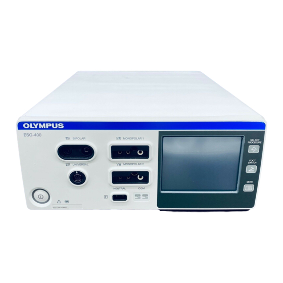
Page 19: Front Panel
ESG-400 5-1-2 Front panel Power on / off Neutral electrode – non-split type Neutral electrode – split type Select procedure Footswitch Menu BIPOLAR socket MONOPOLAR 1 socket UNIVERSAL socket MONOPOLAR 2 socket 5-1-3 Touch screen Double footswitch Single footswitch Autostart... - Page 20 ESG-400 Save procedure Delete procedure Languages Touch tone on Touch tone off Software version Safety test Service Volume Brightness Select procedure (in title line) Menu (in title line) Toggle Previous Next Numeric Alphabetic Uppercase / lowercase Backspace Caution Communication indicator 7.022.211 / ISSUE 5...
-
Page 21: Rear Panel
ESG-400 Reset RCAP Resistance Controlled Automatic Power Reference to BIPOLAR socket Reference to MONOPOLAR 1 socket Reference to UNIVERSAL socket Reference to MONOPOLAR 2 socket 5-1-4 Rear panel Volume Footswitch LINK-IN LINK-IN socket LINK-OUT LINK-OUT socket 7.022.211 / ISSUE 5... -
Page 22: Front Panel
ESG-400 Front panel Power switch This switch turns the electrosurgical generator on and off. BIPOLAR socket This socket connects the plug of a bipolar HF instrument (applied part). MONOPOLAR 2 socket This socket connects the plug of a monopolar HF instrument (applied part). - Page 23 Neutral electrode socket This socket connects the plug of a neutral electrode for monopolar application (applied part). UNIVERSAL socket This socket connects the plug of an Olympus HF instrument with HF instrument recognition (applied part). 7.022.211 / ISSUE 5 23 / 110...
-
Page 24: Rear Panel
ESG-400 Rear panel Footswitch sockets This socket connects the plug of a single or double pedal footswitch. Volume control This knob is used for adjusting the output volume. Ventilation hole Holes for air ventilation via a cooling fan; there are also ventilation holes on each side of the electrosurgical generator. -
Page 25: Bottom Panel
ESG-400 Bottom panel Docking socket This socket connects the plug (7-pin) of a docking connector to connect peripheral equipment. For more details, see chapter 1-6-1. All screen Reference to output sockets indicator This indicator shows the corresponding output socket where the same symbol is printed on the front panel. -
Page 26: Set Screen
ESG-400 autostart or footswitch is not assigned. Refer to chapter 6.4, “Assign footswitch and autostart function”. Procedure name The name of the selected procedure is displayed here. Blank if no procedure is selected. Communication indicator This symbol indicates if communication with peripheral equipment connected to the docking socket is established. -
Page 27: Mode Screen
ESG-400 Toggle button This button switches to the next effect. Return button Press this button to save the settings and to return to the “All screen.” Output power level The number shows the selected output power level. If an output power level is set to zero, “--” will be displayed instead of numbers. -
Page 28: Footswitch With Two Pedals
Footswitch plug Connects the footswitch with the electrosurgical generator on the rear panel. Footswitch with one pedal (optional) The footswitch with one pedal (Olympus REF: WB50403W) is an optional item which may be purchased separately. Coagulation pedal (blue color) This pedal is used to activate the selected coagulation mode. -
Page 29: Neutral Electrode Cable "P-Cord" (Optional)
ESG-400 5-10 Neutral electrode cable “P-cord” (optional) The neutral electrode cable “P-cord” (Olympus REF: MAJ-814) is an optional item for the connection with a neutral electrode which may be purchased separately. Lever-locking arm This arm secures the connector of the neutral electrode with the clamp. -
Page 30: Connector
11) CD APC – Active pin for connection detection 12) CD NEO – Active pin for connection detection Pinning of connector 13 Docking Connector - view of connector side (bottom view) of ESG-400 Monopolar Standard 1 Type: 3 pin Valleylab, pin diameter = 4mm... -
Page 31: Monopolar Neutral Electrode
ESG-400 Function: Bipolar output 1 Neutral electrode 2 Active and neutral electrode Monopolar Neutral Electrode Type: 2 pins socket, Pin diameter = 2.5 mm, Pin distance = 10 mm Function: Monopolar output CQM input Principle sketch of connector 5 Neutral Electrode... -
Page 32: Foot Switch 2 (Sip/Sop)
ESG-400 Foot switch 2 (SIP/SOP) Type: Foot switch, 7-pol. Left Pedal Right Pedal Activation detection of foot switch 7.022.211 / ISSUE 5 32 / 110 Chapter 1: PRODUCT SPECIFICATIONs... -
Page 33: System Diagram
ESG-400 System Diagram The recommended combinations of ancillary equipment and accessories that can be used with the electrosurgical generator are listed in the system chart below. In addition, new products released after the introduction of this product may also become compatible with this electrosurgical generator. For further details, contact Olympus. -
Page 34: Cleaning, Storage And Disposal
ESG-400 Cleaning, storage and disposal The electrosurgical unit may be contaminated with infections materials, therefore, before servicing, perform the following cleaning procedures. For maintenance and storage of other items than those described below, refer to the respective instructions for use. -
Page 35: Storage
In accordance with European Directive 2002/96/EC on waste electrical and electronic equipment (WEEE), the product must not be disposed of as unsorted municipal waste, but should be collected separately. Refer to Olympus for return and / or collection systems available in your country. 7.022.211 / ISSUE 5... - Page 36 ESG-400 7.022.211 / ISSUE 5 36 / 110 Chapter 2: Block Description...
-
Page 37: Chapter 2: Block Description
ESG-400 CHAPTER 2: BLOCK DESCRIPTION 1 BLOCK DESCRIPTIONS ....................38 Motherboard ............................. 39 HVPS Board ............................. 41 Generator board ..........................41 Relay Board ............................. 41 Front Panel ............................42 7.022.211 / ISSUE 5 37 / 110 Chapter 2: Block Description... -
Page 38: Block Descriptions
ESG-400 Block Descriptions Fig. 2.1.1. Block descriptions 7.022.211 / ISSUE 5 38 / 110 Chapter 2: Block Description... -
Page 39: Motherboard
ESG-400 Motherboard Due to the containing embedded PC the Motherboard is the central unit of the ESG-400. The Motherboard controls the Relay Board, the HVPS Board and the Generator Board. It contains all input and output interfaces to the user as well as to other medical devices or computers. Additionally functionalities off the board are the low voltage supplies for the complete unit, the mains input including filters and the measuring part of the voltage line selection circuit for switching between 115 and 230 VAC. - Page 40 ESG-400 Low voltage supplies • Switching regulators for -12 VDC, +5 VDC and +3,3 VDC (5 V and 3,3 V cascaded) • DC/DC converters for isolated +12 VDC and +5 VDC SIP/SOP voltages • Batteries for a permanent +3 V voltage for RTC and SRAM •...
-
Page 41: Hvps Board
ESG-400 HVPS Board The high voltage power supply (HVPS) is a switching mode power supply with series resonance circuit. It provides a high DC voltage for the HF Generator. It contains: • voltage line selection circuit, for automatic change between 110/230 VAC •... -
Page 42: Front Panel
ESG-400 Front Panel The Front Panel is the main part of the user interface. It contains: • LCD touch screen • Push Buttons • Contact Quality Monitor • BIPOLAR socket • MONOPOLAR 1 socket Valleylab & Bovie • MONOPOLAR 2 socket Valleylab & Erbe •... -
Page 43: Chapter 3: Repair System
ESG-400 CHAPTER 3: REPAIR SYSTEM 1 ESG-400 MAIN UNIT ....................44 2 BOARD COMPATIBILITY ..................... 44 3 OPTIONAL ACCESSORIES ..................44 WB50402W (Footswitch with two pedals) ..................44 WB50403W (Footswitch with one pedal) ..................44 MAJ-814 (Neutral electrode cable “P-cord”) ..................44 4 PRECAUTIONS ON FUNCTION AND OPERATION SETTINGS ......... -
Page 44: Main Unit
ESG-400 1 ESG-400 Main Unit In general, the main unit must be shipped to a service center in the event of a malfunction. Individual units can be replaced. 2 Board Compatibility The compatibility of boards and components is dependent on the hardware version of the generator. The hardware version can be indentified by the serial number of the generator. -
Page 45: Chapter 4: Troubleshooting
ESG-400 CHAPTER 4: TROUBLESHOOTING 1 GENERAL ........................46 2 NEUTRAL ELECTRODE OPERATION ................ 47 3 ERROR SCREEN, CODES AND MEASURES ............. 48 What to do when no error code is displayed ..................50 What to do when an error code is displayed ..................54 7.022.211 / ISSUE 5... -
Page 46: General
DANGER Never use the electrosurgical unit if an abnormality is suspected. CAUTION Repairs must only be carried out by Olympus or a firm authorized by Olympus. CAUTION Preventive maintenance (inspection / periodic safety check) must only be carried out by a qualified person / technician. -
Page 47: Neutral Electrode Operation
ESG-400 Neutral electrode operation Check the following table, to identify or correct failures regarding the neutral electrode operation. Contact quality monitor Mode Indication Bipolar application Standby and activation A neutral electrode is not required. Contact quality monitor indicator for split neutral electrode illuminates red. -
Page 48: Error Screen, Codes And Measures
ESG-400 Error screen, codes and measures Follow the troubleshooting advices in this chapter, to identify or correct failures. The error window is configured as shown in figure below. Caution symbol Error code Error title Remedial actions Error window (Example: E002 Short circuit) Fig. - Page 49 ESG-400 NOTE The electrosurgical generator is equipped with an intelligent alarm system which determines alarm conditions on the base of multiple variables. Depending on the risk potential, alarms are classified in “high priority”, “medium priority” and “low priority” alarms. An alarm of higher priority overrides an existing alarm of lower priority.
-
Page 50: What To Do When No Error Code Is Displayed
ESG-400 What to do when no error code is displayed Perform the indicated remedial actions below. If the problem cannot be resolved by the described remedial action, contact the legal manufacturer. Situation Possible cause Remedial action The electrosurgical Improper connection of the power cord to... - Page 51 ESG-400 Situation Possible cause Remedial action No sound is audible The volume is set to an inaudible level Increase the volume either on the touch-screen during activation. (e.g. due to high environmental noise). within the “Menu screen” or use the volume control on the rear panel of the electrosurgical generator.
- Page 52 The HF instrument does not support Confirm the use of an Olympus HF instrument recognize the Olympus HF instrument recognition. with HF instrument recognition capabilities. connected HF instrument.
- Page 53 ESG-400 Situation Possible cause Remedial action No output power is The electrode has no contact with the Check that the electrode has contact with the delivered when tissue. tissue. RFCoag mode with or Improper connection of the HF Check the HF instrument plug for correct...
-
Page 54: What To Do When An Error Code Is Displayed
Check all cables for damage. If necessary, replace the cables. “Cable Damage” Table 4.2: frequently used error messages NOTE The ESG-400 will be restarted automatically when the error with the message of “Auto-restart” is occurred. Error Error message Possible cause... - Page 55 „Contact OLY” E017 Wrong or broken Footswitch, Error 1. Check the Footswitch connection. damaged hardware. „Contact OLY” 2. Change the Footswitch. 3. Send back to Olympus Service E018 Error Refer to E004 „Auto-restart” „Contact OLY” E019 Footswitch Two single pedal or two double...
- Page 56 Error Wrong docking connector coding 1. Check the docking connection to the signal, broken hardware. USG-400. „Auto-restart” 2. Send back to Olympus Service „Contact OLY” E032 Wrong docking connector coding Error 1. Check the docking connection to the signal, broken hardware.
- Page 57 1. Check the FlexRay connections. or other devices. „Contact OLY” 2. Check if all other devices are working properly. 3. Send back to Olympus Service E054 1. Check the FlexRay connections. Error 1. Check the FlexRay connections. 2. Check if all other devices are working properly.
- Page 58 Refer to E045 „Auto-restart” „Contact OLY” E082 Error Refer to E004 E083 „Auto-restart” E084 „Contact OLY” E085 Send back to Olympus Service Error Internal hardware error. […] „Auto-restart” E099 „Contact OLY” E100 Error Spark Monitor communication error. Send back to Olympus Service E101 „Auto-restart”...
- Page 59 ESG-400 Error Error message Possible cause Remedial action E108 Handswitch pressed A pressed Cut Handswitch at the Release the Cut Handswitch at the Monopolar 1 socket has been Monopolar 1 socket and restart the „Release HSW” detected during power-up. device.
- Page 60 „Auto-restart” E130 „Contact OLY” E131 Unknown instrument An Olympus HF instrument has not Check the connection of the Olympus HF been properly connected to the instrument to the UNIVERSAL socket. „Reconnect Instrument” UNIVERSAL socket. „Contact OLY” Invalid default mode detected at the...
- Page 61 „Auto-restart” E145 „Contact OLY” E147 Unknown instrument An Olympus HF instrument has not Check the connection of the Olympus HF been properly connected to the instrument to the UNIVERSAL socket. „Reconnect Instrument” UNIVERSAL socket. „Replace Instrument” The instrument connected to the Change the connected instrument at the „Contact OLY”...
- Page 62 Error message Possible cause Remedial action E153 Unknown instrument An Olympus HF instrument has not Check the connection of the Olympus HF been properly connected to the instrument to the UNIVERSAL socket. „Reconnect Instrument” UNIVERSAL socket. „Replace Instrument” Invalid default Cut Mode detected at Change the Instrument at the „Contact OLY”...
- Page 63 Temperature above Switch off the electrosurgical generator too hot. limit and wait until it has cooled down or reached the specified operating Switch off the ESG-400 temperature. and wait until it has cooled down. „Contact OLY” E181 The generator (HVPS Board) is too...
- Page 64 Unable to read the data at the 1. Change the connected instrument at Multifunction socket. the Multifunction socket. „Auto-restart” 2. Send back to Olympus Service „Contact OLY” E296 Error Unable to write the data from the 1. Change the connected instrument at 7.022.211 / ISSUE 5...
- Page 65 Error message Possible cause Remedial action Multifunction socket. the Multifunction socket. „Auto-restart” „Contact OLY” 2. Send back to Olympus Service E297 Error Unable to read the instrument name 1. Change the connected instrument at from the Multifunction socket. the Multifunction socket.
- Page 66 LINK-OUT / LINK-IN socket: “The 2. Check all other connected devices. „Cable Damage” communication problem to other devices has been detected.” 3. Send back to Olympus Service „Contact OLY” Malfunction or damage of the Check the cables for damages and, if communication cables.
- Page 67 The controlled output power at the Check the connected resistors. Burn-In is below the limit. „Contact OLY” E414 The controlled output power at the Error Send back to Olympus Service Burn-In is above the limit. „Contact OLY” E415 Error Refer to E004 „Auto-restart”...
- Page 68 […] „Auto-restart” E484 „Contact OLY” E486 No instrument An Olympus HF instrument and / or Ensure the proper connection of the connected connection cable has not been Olympus HF instrument and / or the properly connected to the connection cable to the UNIVERSAL Connect an instrument to UNIVERSAL socket.
- Page 69 LINK-OUT / LINK-IN socket: “The 2. Check all other connected devices. „Cable Damage” communication problem to other devices has been detected.” 3. Send back to Olympus Service „Contact OLY” Malfunction or damage of the Check the cables for damages and, if communication cables.
- Page 70 Clean the instrument tip Malfunction of the Olympus HF Replace the Olympus HF instrument and and proceed. instrument and / or the connection / or the connection cable.
- Page 71 ESG-400 Error Error message Possible cause Remedial action E620 Error Internal software error. Send back to Olympus Service […] „Auto-restart” E645 „Contact OLY” E646 Mains voltage drop Mains voltage too low. Check the power cord and the connection (only visible in error log) to the wall outlet.
- Page 72 Replace the HF instrument and / or the and / or the connection cable. connection cable. „Replace Instrument” „Contact OLY” E669 Error Internal software error. Send back to Olympus Service […] „Auto-restart” E671 „Contact OLY” E672 Error Internal software or hardware error.
-
Page 73: Chapter 5: Inspection
ESG-400 CHAPTER 5: INSPECTION 1 JIGS, TOOLS, AND MEASURING EQUIPMENT FOR INSPECTION ......74 2 INSPECTION PROCEDURES ..................75 Visual inspection of the electrosurgical generator and accessories ..........76 Verifying the contact quality monitor function .................. 80 Checking the DC resistance (according to IEC 60601-2-2) ............. 82 Checking the earth resistance (according to IEC 60601-1 and IEC 62353) ........ -
Page 74: Jigs, Tools, And Measuring Equipment For Inspection
MAJ-1871 Communication cable, length 0.25 m J013 Crocodile clips (with 4 mm connection) For connection to Potential Equalization bonding J014 ESG-400 foot switch double pedal WB50402W J015 ESG-400 foot switch single pedal WB50403W J016 Power Cord Ordering depending on country. Refer to... -
Page 75: Inspection Procedures
ESG-400 Inspection procedures The electrosurgical generator and the footswitch must undergo an inspection / safety check in yearly intervals in accordance with the national statutory regulations. Inspection is also mandatory after repair, adjustment, update and upgrade. Generally the footswitches are inspected together with the electrosurgical unit. If a footswitch alone has to be checked, only following tests are mandatory. -
Page 76: Visual Inspection Of The Electrosurgical Generator And Accessories
ESG-400 Visual inspection of the electrosurgical generator and accessories Check that the labels according to chapter 5-1 (Front panel, Rear panel) are present and legible. The product name should be clearly visible on the front panel. Verify that the type plate shows details about the type of the device, reference number, line voltage range, supply frequency, output power classification, output frequency, duty cycle, serial number, manufacturing date and manufacturer according to Fig. - Page 77 ESG-400 12345W13-678 2013-03 Fig. 5.2.3 Sample of type plate of the electrosurgical unit (Japan Version) Fig. 5.2.4 Sample of type plate of the electrosurgical unit (China Version) Check the electrosurgical unit and the accessories for external obstructions or damage. Verify that the housing, the front panel and the rear panel have no serious destructions.
- Page 78 ESG-400 electrosurgical generator. Fill out the table 7.1 after the first startup of the generator. The field “Actual Procedure” can only be filled, if a procedure is chosen. The table 7.2 is used every time before a mode is changed in order to perform a test. The settings of the used mode are noted in one line of table 7.2.
- Page 79 ESG-400 Actual <if applicable> Procedure Actual BIPOLAR MONOPOLAR 1 Screen Cut Mode Coag Mode Cut Mode Coag Mode UNIVERSAL MONOPOLAR 2 Cut Mode Coag Mode Cut Mode Coag Mode Table 7.1: Template to note the actual procedure and the user assignment of the modes to the sockets...
-
Page 80: Verifying The Contact Quality Monitor Function
ESG-400 Verifying the contact quality monitor function Connect the power cord and the footswitch to the electrosurgical generator (refer to chapter 1-5-3 and 1-5-8). All steps for this test are described in the table 7.3 at the next page. Assign the footswitch according to the column “Mode”. - Page 81 ESG-400 NOTE Always disconnect the neutral electrode connector (J011) before connecting a new resistor. Mode Action Expected test result During standby bipolar activation mode The neutral electrode socket is left open, The contact quality monitor is nothing is connected. independent from the bipolar mode.
-
Page 82: Checking The Dc Resistance (According To Iec 60601-2-2)
ESG-400 Checking the DC resistance (according to IEC 60601-2-2) Activate the safety test function in the service menu (see chapter 6-1, Safety Test) and verify that the button “Relays on” is marked white. Connect the digital multimeter (J003) with the bipolar connector on the front panel (see chapter 1-5-2). -
Page 83: Checking The Patient Leakage Current (According To Iec 60601-1)
ESG-400 Checking the patient leakage current (according to IEC 60601-1) NOTE For this test an interconnection of the three receptacles of MONOPOLAR 1 and MONOPOLAR 2 is allowed. Before interconnect the three receptacles verify, that the safety test function is activated and the button “Relays on” is marked white. -
Page 84: Checking The Current And Power Consumption And Output Waveform
ESG-400 Checking the current and power consumption and output waveform CAUTION A connection of a 4 mm plug to any other receptacle except the right-hand-side receptacle the MONOPOLAR socket the MONOPOLAR 2 socket may destroy the socket during activation. = 500 Ω (J005) via a 4mm cable “banana” (J007) to the right receptacle of Connect the load resistor R the MONOPOLAR 1 socket and via the connection cable “P-cord”... - Page 85 ESG-400 11) Select the SalineCut (Effect 3) mode at the UNIVERSAL socket. Set the level to 320. Assign the footswitch to the UNIVERSAL socket. (Perform the setting according to the instruction for use.) 12) Activate the output power by pressing “CUT” at the footswitch.
-
Page 86: Checking The High Frequency Leakage Current (According To Iec 60601-2-2)
ESG-400 Checking the high frequency leakage current (according to IEC 60601-2-2) The monopolar high frequency leakage current has to be measured according to the procedure 19.3.101 a) 2) (neutral electrode isolated from earth at high frequency) as described in IEC 60601-2-2. - Page 87 ESG-400 Fig. 5.2.3. Example for the loaded measurement of the monopolar high frequency leakage current at the neutral pole Fig. 5.2.4. Example for the loaded measurement of the monopolar high frequency leakage current at the active pole CAUTION A connection of a 4 mm plug to any other receptacle except the right-hand-side receptacle of the MONOPOLAR 1 socket and the MONOPOLAR 2 socket may destroy the socket during activation.
-
Page 88: Measurement Of The Monopolar High Frequency Leakage Current Under Unloaded Condition
ESG-400 2-8-2 Measurement of the monopolar high frequency leakage current under unloaded condition CAUTION A connection of a 4 mm plug to any other receptacle except the right-hand-side receptacle the MONOPOLAR socket the MONOPOLAR 2 socket may destroy the socket during activation. - Page 89 ESG-400 Fig. 5.2.5. Example for the unloaded measurement of the monopolar high frequency leakage current at the neutral pole Fig. 5.2.6. Example for the unloaded measurement of the monopolar high frequency leakage current at the active pole CAUTION A connection of a 4 mm plug to any other receptacle except the right-hand-side receptacle of the MONOPOLAR 1 socket and the MONOPOLAR 2 socket may destroy the socket during activation.
-
Page 90: Measurement Of The Bipolar High Frequency Leakage Current Under Loaded Condition
ESG-400 2-8-3 Measurement of the bipolar high frequency leakage current under loaded condition CAUTION A connection of a 4 mm plug to any other receptacle except the right-hand-side receptacle the MONOPOLAR socket the MONOPOLAR 2 socket may destroy the socket during activation. - Page 91 ESG-400 Fig. 5.2.7. Example for the loaded measurement of the bipolar high frequency leakage current at terminal 1 Fig. 5.2.8. Example for the loaded measurement of the bipolar high frequency leakage current at terminal 2 7.022.211 / ISSUE 5 91 / 110...
-
Page 92: Measurement Of The Bipolar High Frequency Leakage Current Under Unloaded Condition
ESG-400 2-8-4 Measurement of the bipolar high frequency leakage current under unloaded condition Fig. 5.2.10 and Fig. 5.2.11 are showing an example how to set up the test to measure the bipolar high frequency leakage current under unloaded condition. In this test the output is unloaded, the load resistance used in the test before is removed. - Page 93 ESG-400 Fig. 5.2.9. Example for the unloaded measurement of the bipolar high frequency leakage current at terminal 1 Fig. 5.2.10. Example for the unloaded measurement of the bipolar high frequency leakage current at terminal 2 7.022.211 / ISSUE 5 93 / 110...
-
Page 94: Checking The Output Power
ESG-400 Checking the output power All constraints for these tests are listed in the inspection card in chapter 5-3 under number 31 to 47. The constraints are the output socket, the way of activation (e.g. footswitch, handswitch), the settings and the load resistance. -
Page 95: Final Test
ESG-400 2-11 Final test 2-11-1 Self test Connect the electrosurgical generator via power cord (J016) to mains. Switch the generator on by pressing the “Power Switch”. The generator should boot without any alarm. If an alarm occurs, refer to Chapter 4 (Troubleshooting). -
Page 96: Restore Of Output Power Settings
ESG-400 (J012) with each other. In this way a ring communication is established. The Error Message “E394 Communication error” should appear. Record the test results in the Inspection Card (refer to chapter 5-3). 2-11-5 Restore of output power settings Restore the settings by using the tables created in chapter 7-2-1. When not done while inspecting, restore all power settings off the changed modes noted in table 7.2. -
Page 97: Inspection Card
ESG-400 3 Inspection Card Product name: REF no.: Serial no.: Software version: Service / Maintenance manual version: Test type / mode Pwr. Load Requirement Measured Test passed level resistance value Effect Visual inspection of the electrosurgical unit and accessories Labels... - Page 98 ESG-400 Test type / mode Pwr. Load Requirement Measured Test passed level resistance value Effect Patient leakage current ≤ 0.01 mA Normal condition (NC), AC ≤ 0.01 mA Normal condition (NC), DC Single fault condition (SFC), ≤ 0.05 mA Single fault condition (SFC), ≤...
- Page 99 ESG-400 Test type / mode Pwr. Load Requirement Measured Test passed level resistance value Effect BipolarCut 500 Ω ≤ 70 mA (active electrode terminal 1) Eff. 3 BipolarCut 500 Ω ≤ 70 mA (active electrode terminal 2) Eff. 3 BipolarCut ≤...
- Page 100 ESG-400 Test type / mode Pwr. Load Requirement Measured Test passed level resistance value Effect BipolarCut 500 Ω 82 W ≤ P ≤ 122 W (double foot switch Eff. 3 @ BIPOLAR) Bipolar AutoCoag (single foot switch (if 25 Ω...
- Page 101 ESG-400 Test type / mode Pwr. Load Requirement Measured Test passed level resistance value Effect Checking for certain error messages Bipolar FineCoag Message “E002 Short 7 Ω (foot switch @ BIPOLAR) circuit” Eff. 1 Bipolar HardCoag Message “E001 Open 10 kΩ...
- Page 102 ESG-400 7.022.211 / ISSUE 5 102 / 110 Chapter 5: Inspection...
-
Page 103: Chapter 6: Device Menu
ESG-400 CHAPTER 6: DEVICE MENU 1 SAFETY TEST ......................104 2 SOFTWARE VERSION ....................105 7.022.211 / ISSUE 5 103 / 110 Chapter 6: Device Menu... -
Page 104: Safety Test
ESG-400 Safety Test This function closes the output relays to perform the measurement(s) required during the inspection. Activation of this function disables the electrosurgical unit for normal operation. Press the “MENU push button” to display the “Select Menu Screen” on the touch-screen. -
Page 105: Software Version
ESG-400 Software Version Press the “MENU push button” to display the “Select Menu Screen” on the touch-screen. Switch to the next menu page by pressing the “Next button”. Press the Button “Software version”. Read out the software version and leave the menu by pressing the button “OK”. - Page 106 ESG-400 7.022.211 / ISSUE 5 106 / 110 Chapter 6: Device Menu...
-
Page 107: Chapter 7: Revision History
ESG-400 CHAPTER 7: REVISION HISTORY 7.022.211 / ISSUE 5 107 / 110 Chapter 7: Revision History... -
Page 108: Revision History
ESG-400 Revision History REF No. / Revision No. Release date Modifications description 7.022.211 12/04 2012-04-27 First clearance Chapter 5-1: Added ESG-Textbox to the Jigs and tools list 7.022.211 12/09 2012-10-12 W-CR-11829 Chapter 5-1: Added J017 Oscilloscope to the Jigs and tools... - Page 109 Chapter 4-3: Fig 4-3-1 updated, added NOTE “The OK button is not available…” Chapter 4-3-2: • Added Table 4.2; added NOTE “The ESG-400 will be restarted automatically…” • Updated all error codes regarding their display error messages; detailed overview of all error messages •...
- Page 110 Fax: +7 495 958 2277, Phone: +7 495 720 9332 http://www.olympus.com.ru/ OLYMPUS (BEIJING) SALES & SERVICE CO. LTD. Rm. 1202, NCI Tower, A12 Jianguomenwai Avenue, Chaoyang District, Beijing 100022, China Fax: +86 10 6569 3555, Phone: +86 10 6569 3535 http://cn.olympus.com/...
Need help?
Do you have a question about the ESG-400 and is the answer not in the manual?
Questions and answers