
Related Manuals for Ledj TPix Strip & Controller MKII Series


Summary of Contents for Ledj TPix Strip & Controller MKII Series
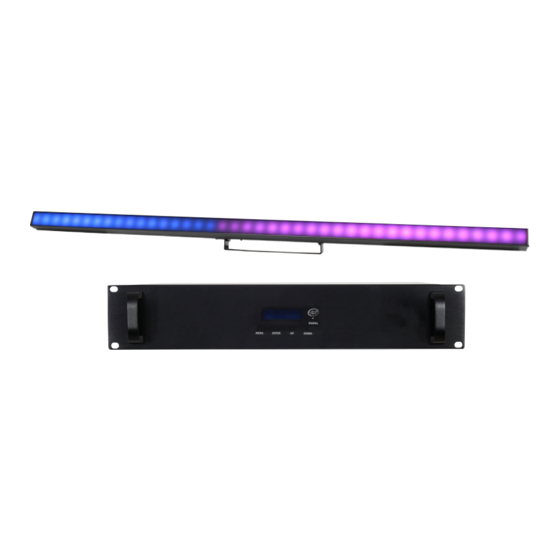
- Page 1 TPix Strip & Controller MKII User Manual Order code: TPix Strip 40 MKII - LEDJ485 TPix Strip 80 MKII - LEDJ486 TPix Strip 40 Controller MKII - LEDJ487 TPix Strip 80 Controller MKII - LEDJ488...
-
Page 2: Safety Advice
Safety advice WARNING FOR YOUR OWN SAFETY, PLEASE READ THIS USER MANUAL CAREFULLY BEFORE YOUR INITIAL START-UP! • Before your initial start-up, please make sure that there is no damage caused during transportation. • Should there be any damage, consult your dealer and do not use the equipment. •... - Page 3 Product overview & technical specifications TPix Strip & Controller MKII The TPix strips are pixel mappable strips controllable by DMX, Art-Net or Kling-Net. They feature a wide 120° viewing angle and feature a milky, frost effect front screen. Black and clear front screens are included to further expand the versatility of these fixtures.
-
Page 4: Technical Specifications
Technical specifications TPix Strip RJ45 INPUT RJ45 OUTPUT DATA & POWER DATA & POWER RJ45 INPUT RJ45 OUTPUT DATA & POWER DATA & POWER In the box: 1 x fixture, 1 x clear front screen, 1 x frosted front screen, 1 x black front screen, 1 x RJ45 signal cable 01 - RJ45 Data/Power input... -
Page 5: Network Settings
Operating instructions DMX Address DMX Address DMX address setting DMX Address DMX CH Mode 10CH DMX CH Mode 55CH DMX CH Mode DMX channel setting DMX CH Mode 480CH DMX CH Mode NET-PIXEL Auto Mode Speed: 1 Auto mode speed setting Auto Mode Speed: 9 Auto Mode... - Page 6 Operating instructions IMPORTANT! PLEASE NOTE: The LCD display for this fixture has a timer that turns the display back- light off after 25 seconds of inactivity. To illuminate the display again press one of the 4 buttons. DMX mode: Operating in a DMX control mode environment gives the user the greatest flexibility when it comes to customising or creating a show.
- Page 7 Operating instructions 55 channel mode: Channel Value Function Channel Value Function 000-255 Master dimmer (0-100%) 185-221 Pink cont. 000-255 Strobe (slow-fast) 222-255 White 000-001 Blackout 000-255 Sound mode (colour change) (For 002-017 Macro 1 000-255 Red dimmer (0-100%) macro Output 1 018-034 Macro 2 000-255 Green dimmer (0-100%)
- Page 8 Operating instructions 55 channel mode: 480 channel mode: Channel Value Function Channel Value Function 44CH 000-255 Red dimmer (0-100%) 000-255 Red dimmer (0-100%) Output 4 LEDs 1-4 (40), 1-8 (80) 45CH 000-255 Green dimmer (0-100%) Fixture 1 000-255 Green dimmer (0-100%) 46CH 000-255 Blue dimmer (0-100%) LEDs 1-4 (40), 1-8 (80)
-
Page 9: Master/Slave Mode
Operating instructions ArtNet/KlingNet mode: Please note: For full pixel control, ArtNet/KlingNet must be used with the fixture in PIXEL-NET mode. This will allow full control of each pixel. To access the ArtNet/KlingNet mode, press the “MENU” button and use the “UP” and “DOWN” but- tons to show “DMX CH Mode”... - Page 10 Operating instructions Subnet Mask setting : To access the Subnet Mask setting, press the “MENU” button and use the “UP” and “DOWN” buttons to show “NETWORK SETUP” on the LCD display. Now press the “ENTER” button and use the “UP” and “DOWN”...
-
Page 11: Connecting To A Network
Connecting to a Network KlingNet Settings: 01) Install a KlingNet based software on your PC (Windows or Mac). 02) Connect the TPix Strip to the TPix Strip Controller via the RJ45 outputs. 03) Connect the TPix Strip Controller to a power supply via the PowerCON input. 04) Make sure the PC has a fixed IP Address. -
Page 12: Wiring Diagrams
Wiring diagrams 5-PIN DMX 3-PIN DMX RJ45 RJ45 3-PIN DMX 5-PIN DMX INPUT INPUT INPUT OUTPUT OUTPUT OUTPUT OUTPUT TO TPIX STRIP (DATA + POWER) Artnet/Klingnet Universe 4 Universe 3 Universe 2 Universe 1 Please note: You must always go from the TPix Controller RJ45 output into a TPix Strip input and then from a TPix Strip RJ45 output to TPix Strip RJ45 input to link TPix Strips. - Page 13 Making a data cable: A standard ETHERNET cable can be used to replace the data cable required to transmit the data. Please follow the instructions below in order to create extra cables: Take a standard net cable (CAT-5/CAT-5E/CAT-6) and connect it to an RJ45 connector as shown below. 12345678 12345678 87654321...
-
Page 14: Dmx Setup
DMX setup Setting the DMX address: The DMX mode enables the use of a universal DMX controller. Each fixture requires a “start address” from 1- 512. A fixture requiring one or more channels for control begins to read the data on the channel indicated by the start address. -
Page 15: Line Termination
DMX setup Notice: Be sure to follow the diagrams below when making your own cables. Pin Configuration Do not connect the cables shield conductor to the ground lug or 3-Pin 5-Pin allow the shield conductor to come in contact with the XLRs Pin 1 - Ground outer casing. -
Page 16: Weee Notice
WEEE notice Correct Disposal of this Product (Waste Electrical & Electronic Equipment) (Applicable in the European Union and other European countries with separate collection systems) This marking shown on the product or its literature, indicates that it should not be disposed with other household wastes at the end of its working life.
Need help?
Do you have a question about the TPix Strip & Controller MKII Series and is the answer not in the manual?
Questions and answers