Table of Contents
Advertisement
STORM
INSTRUCTIONS FOR
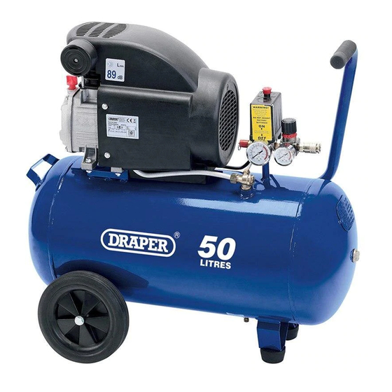
230V 50L
Air Compressor
Stock No' s .30886
Part No' s .DA50/207/BK
IMPORTANT: PLEASE READ THESE INSTRUCTIONS CAREFULLY TO ENSURE THE SAFE AND
EFFECTIVE USE OF THIS PRODUCT.
GENERAL INFORMATION
These instructions accompanying the product are the original instructions. This document is part of the product, keep it
for the life of the product passing it on to any subsequent holder of the product. Read all these instructions before
assembling, operating or maintaining this product.
This manual has been compiled by Draper Tools describing the purpose for which the product has been designed, and
contains all the necessary information to ensure its correct and safe use. By following all the general safety instructions
contained in this manual, it will ensure both product and operator safety, together with longer life of the product itself.
AlI photographs and drawings in this manual are supplied by Draper Tools to help illustrate the operation of the product.
Whilst every effort has been made to ensure the accuracy of information contained in this manual, the Draper Tools policy
of continuous improvement determines the right to make modifications without prior warning.
Advertisement
Table of Contents

Related Manuals for Draper Stormforce DA50/207/BK


Summary of Contents for Draper Stormforce DA50/207/BK
-
Page 1: Air Compressor
AlI photographs and drawings in this manual are supplied by Draper Tools to help illustrate the operation of the product. -
Page 2: Title Page
Commercial copying, redistribution, hiring or lending is prohibited. No part of this publication may be stored in a retrieval system or transmitted in any other form or means without written permission from Draper Tools Limited. In all cases this copyright notice must remain intact. -
Page 3: Table Of Contents
CONTENTS 2.1 CONTENTS PAGE CONTENT PAGE TITLE PAGE INTRODUCTION ....................2 REVISION HISTORY................... 2 UNDERSTANDING THIS MANUAL ..............2 COPYRIGHT NOTICE ..................2 CONTENTS CONTENTS ......................3 GUARANTEE GUARANTEE ..................... 4 INTRODUCTION SCOPE ....................... 5 SPECIFICATION ....................5 HANDLING & STORAGE ................... 5 HEALTH &... -
Page 4: Guarantee
This guarantee applies in lieu of any other guarantee expressed or implied and variations of its terms are not authorised. Your Draper guarantee is not effective unless you can produce upon request a dated receipt or invoice to verify your proof of purchase within the guarantee period. -
Page 5: Introduction
INTRODUCTION 4.1 SCOPE The compressor described in this manual is capable of supplying compressed air to a maximum pressure of 8bar. to operate pneumatic tools for a variety of applications including blowing, spraying and tyre inflating. 4.2 SPECIFICATION Stock No..........................30886 Part No. -
Page 6: Health & Safety Information
HEALTH & SAFETY INFORMATION 5.1 GENERAL SAFETY INSTRUCTIONS FOR POWER TOOL USE When using any type of power tool there are steps that should be taken to make sure that you, as the user, remain safe. Common sense and a respect for the tool will help reduce the risk of injury. Read the instruction manual fully. - Page 7 HEALTH & SAFETY INFORMATION Wear personal protective equipment (PPE). Dust, noise, vibration and swarf can all be dangerous if not suitably protected against. If the work involving the power tool creates dust or fumes; wear a dust mask. Vibration to the hand, caused by operating some tools for longer periods must be protected against.
-
Page 8: Additional Safety Instructions For Safety Valves
HEALTH & SAFETY INFORMATION Have this tool repaired by a qualified person. This tool is designed to confirm to the relevant international and local standards and as such should be maintained and repaired by someone qualified; using only original parts supplied by the manufacturer: This will ensure the tool remains safe to use. -
Page 9: Additional Safety Instructions For Pressure Vessels
HEALTH & SAFETY INFORMATION 5.3 ADDITIONAL SAFETY INSTRUCTIONS FOR PRESSURE VESSELS • This pressure tank is mainly intended for static use. It can only be charged with natural air within temperature and pressure limits as specified on the manufacturer's plate and declaration of conformity. - Page 10 Blank page...
-
Page 11: Unpacking & Checking
Lay the contents out and check them against the parts shown below. If any part is damaged or missing; please contact the Draper Helpline (the telephone number appears on the Title page) and do not attempt to use the compressor. - Page 12 TECHNICAL DESCRIPTION 6.1 IDENTIFICATION Pump housing Transport handle On/Off pressure switch button Pressure regulator Air outlet quick connector Safety valve Tank pressure gauge Outlet air gauge Pressure switch Oil plug Oil level indicator Drain cock Air filter Tank...
-
Page 13: Preparing The Compressor
PREPARING THE COMPRESSOR NOTE: Remove the plug from the socket before carrying out adjustment, servicing or maintenance. 8.1 LOCATION AND ASSEMBLY - FIGS. 1-2 It is extremely important to install the compressor in a clean, well ventilated area where the surrounding air temperature will not be more than 40ºC. -
Page 14: Operation
OPERATION 9.1 BASIC COMPRESSOR OPERATION – FIGS. 4-5 – Connect the air line to the compressor by pulling back the collar on the air outlet quick coupling and inserting the corresponding air coupling fitted on the air line. Release the collar so it slides back in place to secure the air coupling. -
Page 15: Thermal Overload Protector
OPERATION 9.4 THERMAL OVERLOAD PROTECTOR CAUTION: THIS COMPRESSOR IS EQUIPPED WITH AN AUTOMATIC RESET THERMAL OVERLOAD PROTECTOR, WHICH WILL SHUT OFF THE MOTOR IF IT BECOMES OVERHEATED. If thermal overload protector shuts motor OFF frequently, look for the following causes. –... -
Page 16: Troubleshooting
10. TROUBLESHOOTING Motor won’t run. 1. No electrical power 1. Check the power supply. 2. Power wiring too thin or 2. Replace the wire. Motor running too long. too slow or getting too hot. 3. Fault in pressure switch. 3. Repair or replace. 4. -
Page 17: Maintenance
11. MAINTENANCE 11.1 BASIC MAINTENANCE AND CHECKS – FIGS. 7-8 NOTE: Remove the plug from the socket before carrying out adjustment, servicing or maintenance. In order to maintain the compressor, periodical service checks must be carried out routinely. Allowances should be made to adjust the time scale for machines in occasional service with the exception of the safety valve which must be inspected by a qualified service agent... -
Page 18: General Maintenance And Service Intervals
11. MAINTENANCE 11.2 GENERAL MAINTENANCE AND SERVICE INTERVALS – FIGS. 9-11 After the first 10 working hours: – Clean crankcase and renew lubricating oil. After every 20 working hours: – Check the oil level and replensish if necessary. After every 50 working hours: –... -
Page 19: Explanation Of Symbols
12. EXPLANATION OF SYMBOLS 12.1 EXPLANATION OF SYMBOLS Warning! Warning! Read the instruction manual Wear dust mask. Warning! Warning! Wear ear defenders. Wear goggles. WEEE Do not dispose of Waste Electrical & Electronic Equipment in with domestic rubbish... -
Page 20: Disposal
13. DISPOSAL 13.1 DISPOSAL - At the end of the machine’s working life, or when it can no longer be repaired, ensure that it is disposed of according to national regulations. - Contact your local authority for details of collection schemes in your area. In all circumstances: •... -
Page 21: Glossary
14. GLOSSARY 14.1 GLOSSARY Alphabetical list of words relating to this manual Check valve A one-way valve that allows air to enter the tank but prevents air in the tank from flowing back into the compressor pump. Regulator The regulator controls the amount of air pressure released at the hose outlet. - Page 22 - Sales Fax: (023) 8049 4209 - General Enquiries: (023) 8026 6355 - Service/Warranty Repair Agent For aftersales servicing or warranty repairs, please contact the Draper Tools Helpline for details of an agent in your local area. YOUR DRAPER STOCKIST RWCH150313...
Need help?
Do you have a question about the Stormforce DA50/207/BK and is the answer not in the manual?
Questions and answers