Planmeca proline xc Installation Manual
Hide thumbs
Also See for proline xc:
- User manual (30 pages) ,
- User manual (66 pages) ,
- Technical manual (258 pages)
Table of Contents
Advertisement
Advertisement
Table of Contents

Related Manuals for Planmeca proline xc


Summary of Contents for Planmeca proline xc
- Page 1 installation manual...
-
Page 3: Table Of Contents
Planmeca Proline XC pan/ceph X-ray - checking the alignment of the radiation beam .... 21 Planmeca Proline XC pan/ceph X-ray - checking the position of the soft tissue filter ....31 Planmeca Proline XC pan/ceph X-ray - checking the alignment of the head support ....33 Checking the alignment of the patient positioning mechanism .......... - Page 4 Table of Contents Planmeca pursues a policy of continual product development. Although every effort is made to produce up-to-date product documentation this publication should not be regarded as an infallible guide to current specifications. We re- serve the right to make changes without prior notice.
-
Page 5: Introduction
This guide contains all the information required to set up and calibrate both versions of the Planmeca Proline XC X-ray. NOTE You may also need the Planmeca Proline XC X- ray unit’s technical manual (publication number 10010942) during installation. The alignment in- structions are given in technical manual. -
Page 6: Pre-Installation Information
2.5 meters (8 feet) of where the X-ray is to be installed. 5. Make sure that you have access to an X-ray film pro- cessor that is in working order and is ready for use. 2 Planmeca Proline XC X-ray unit Installation manual... - Page 7 X-ray film being used. 8. Make sure that the X-ray film will fit the cassette and that it can be used with the intensifying screen being used. Installation manual Planmeca Proline XC X-ray unit 3...
-
Page 8: Installation Dimensions
W(standard Pan) 1530 (60") 440 (17") 730 (29") 360 (14") 830 (32 1/2") NOTE: If the unit is to be used with the free-standing base (part number 50021) the total height will be 2230mm (88in) 4 Planmeca Proline XC X-ray unit Installation manual... -
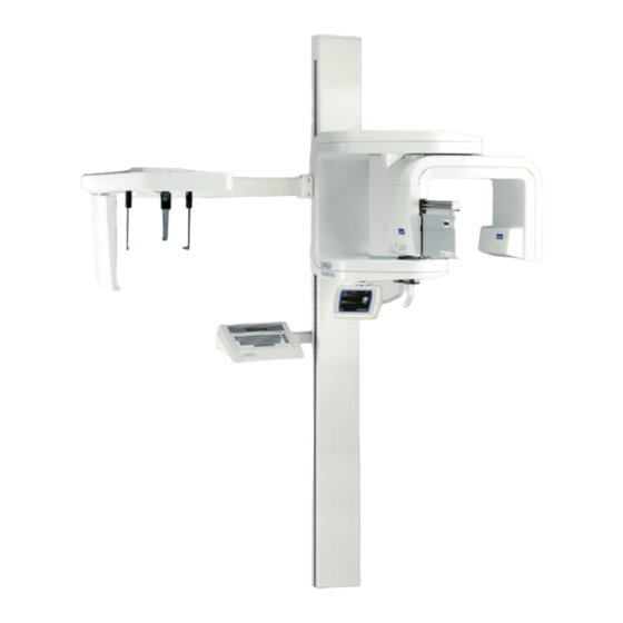
Page 9: X-Ray Unit Main Parts
2.3 X-ray unit main parts Tube head assembly Rotating unit Column Cassette carriage assembly Vertical carriage Cephalostat (optional) Lower shelf Admark film-marking system (optional) Graphic user interface Autoprint film-marking system (optional) Exposure switch Installation manual Planmeca Proline XC X-ray unit 5... -
Page 10: Calibration Tools
PRE-INSTALLATION INFORMATION 2.4 Calibration tools You will need the following PLANMECA calibration tools to check the alignment of the X-ray: Beam alignment tool Alignment ruler (Part number 50972) (Part number 50973) Used to check the position of Used to check the position of the... -
Page 11: Installing The X-Ray
Unpack the unit but DO NOT REMOVE THE PROTEC- TIVE STYROFOAM PACKAGING UNTIL THE UNIT HAS BEEN ATTACHED TO THE WALL AND LEV- ELLED. If you have the carry handles (PLANMECA part number 50985) attach them to the support column. Transport the unit to the installation position. - Page 12 Wall bracket Screws With a spirit level make sure that the column is vertical. If Wall bracket you have to make any adjustments move the base of the column. Column Spirit level 8 Planmeca Proline XC X-ray unit Installation manual...
- Page 13 Remove the protective styrofoam packaging and the tape that you previously wrapped round the top of the column to stop the wall bracket from sliding down. Wall bracket Clamping screws Bottom of column Lower bracket Installation manual Planmeca Proline XC X-ray unit 9...
- Page 14 The long transportation pin that holds the rotating unit in position is used to check that the unit is correctly aligned. Clamping screw Transportation pin Vertical carriage Transportation pins Rotating unit Column Counterweight locking screw and clamp plate 10 Planmeca Proline XC X-ray unit Installation manual...
-
Page 15: Installing The Exposure Switch
X- ray column. It does not matter which socket the cable is Exposure connected to. switch Bottom of cable column Male plug Installation manual Planmeca Proline XC X-ray unit 11... -
Page 16: Planmeca Proline Xc Pan/Ceph X-Ray - Attaching The Cephalostat
INSTALLING THE X-RAY 3.3 Planmeca Proline XC pan/ceph X-ray - Attaching the Cephalostat If you are installing a Planmeca Proline XC PAN/CEPH unit you must attach the cephalostat to the vertical car- riage. Lift the cephalostat and carefully guide the cephalostat arm round the back of the X-ray so that the adaptor is behind the vertical carriage. -
Page 17: Checking The Alignment
NOTE A help message is shown on the GUI if the select- ed function is not allowed. The help message disappears when you cancel the action or re- lease the exposure button. Installation manual Planmeca Proline XC X-ray unit 13... - Page 18 From the list of User settings select Behavioural prefer- ences . The display shown below appears. Touch the Test mode field to enter the test mode (ON). Exit the test mode by touching the Test mode field again (OFF). 14 Planmeca Proline XC X-ray unit Installation manual...
- Page 19 Touch the i-field on the Main display. The list of User preference settings appears. By touching the arrow down field below the list you can see more features. From the list of User settings select Service settings (password). Installation manual Planmeca Proline XC X-ray unit 15...
- Page 20 The password is 1701. Exit the service mode by touching the OK field on the respective service mode display and on the Service set- tings display. 16 Planmeca Proline XC X-ray unit Installation manual...
-
Page 21: Planmeca Proline Xc Panoramic X-Ray - Checking The Alignment Of The Radiation Beam
CHECKING THE ALIGNMENT 4.2 Planmeca Proline XC panoramic X-ray - checking the alignment of the radia- tion beam Remove the inner cover from tube head assembly. Four screws hold the tube head cover in position, these are located at the rear of the tube head assembly. The pri- mary collimator mechanism is located under the tube head cover. - Page 22 62kV and 6mA. The actual values will depend on how dark the room is. 18 Planmeca Proline XC X-ray unit Installation manual...
- Page 23 Stand behind the tube head and protect yourself from radiation. Press and hold down the exposure button. The image of the radiation beam will appear on the align- ment tool. Installation manual Planmeca Proline XC X-ray unit 19...
- Page 24 The radiation beam must appear within the borders of the rectangle marked on the alignment tool. If it does not refer to the Planmeca Proline XC panoramic X-ray tech- nical manual for information on how to align it. Radiation beam...
-
Page 25: Planmeca Proline Xc Pan/Ceph X-Ray - Checking The Alignment Of The Radiation Beam
CHECKING THE ALIGNMENT 4.3 Planmeca Proline XC pan/ceph X-ray - checking the alignment of the radiation beam Panoramic X-ray beam Remove the inner covers from tube head assembly and the cassette drive assembly. Four screws hold the tube head cover in position, these are located at the rear of the tube head assembly. - Page 26 An error code will appear on the display. Clear the error code from the display by touching the OK field. Exit the Test mode. On the main display, touch the kV / mA field. 22 Planmeca Proline XC X-ray unit Installation manual...
- Page 27 Enter the service mode (See section “Service mode” on page 15). By touching the arrow down field below the list you can see more features. From the list of Service set- tings select Primary collimator. Installation manual Planmeca Proline XC X-ray unit 23...
- Page 28 The radiation beam must appear within the borders of the rectangle marked on the alignment tool. If it does not refer to the Planmeca Proline XC X-ray unit technical manual for information on how to align it. Radiation beam...
- Page 29 If the beam is not aligned correctly refer to the x-ray unit’s technical manual. Exit the service mode, see “Service mode” on page 15. Cephalometric X-ray beam Select the Cephalostat program as follows. Touch the Prog. field on the main display. Installation manual Planmeca Proline XC X-ray unit 25...
- Page 30 Position it so that it is on the left of the cas- holder sette holder. Beam alignment tool PLANMECA PM 2002 Proline Cephalostat 18x24 No. 652232 Select the collimator number 4. 26 Planmeca Proline XC X-ray unit Installation manual...
- Page 31 The radiation beam must appear within the borders of the rectangle marked on the alignment tool. If it does not refer to the Planmeca Proline XC Pan/Ceph X-ray unit technical manual for information on how to align it. Radiation beam...
- Page 32 The radiation beam must appear within the borders of the rectangle marked on the alignment tool. If it does not refer to the Planmeca Proline XC Pan/Ceph X-ray unit technical manual for information on how to align it. Radiation beam...
- Page 33 Stand behind the tube head and protect yourself from radiation. Press and hold down the exposure button. The image of the radiation beam from collimator number 6 will appear on the alignment tool. Installation manual Planmeca Proline XC X-ray unit 29...
- Page 34 The radiation beam must appear within the borders of the rectangle marked on the alignment tool. If it does not refer to the Planmeca Proline XC Pan/Ceph X-ray unit technical manual for information on how to align it. Radiation beam...
-
Page 35: Planmeca Proline Xc Pan/Ceph X-Ray - Checking The Position Of The Soft Tissue Filter
CHECKING THE ALIGNMENT 4.4 Planmeca Proline XC pan/ceph X-ray - checking the position of the soft tissue filter Clip the soft tissue filter positioning tool to the soft tissue filter which is at the end of the cassette carriage. This will... - Page 36 “Soft tissue filter 0mm” or extends passed the line the soft tissue filter is in the wrong posi- tion it must be repositioned. Refer to the Planmeca Pro- line XC Pan/Ceph X-ray unit technical manual for information on how to carry out this task.
-
Page 37: Planmeca Proline Xc Pan/Ceph X-Ray - Checking The Alignment Of The Head Support
CHECKING THE ALIGNMENT 4.5 Planmeca Proline XC pan/ceph X-ray - checking the alignment of the head support Rotate the head support to the 90° position and place the two ear posts into their holders if they are not already installed. -
Page 38: Checking The Alignment Of The Patient Positioning Mechanism
CHECKING THE ALIGNMENT 4.6 Checking the alignment of the patient positioning mechanism NOTE If the PLANMECA AUTOPRINT film marking sys- tem is to be used with the X-ray you can check the operation of the AUTOPRINT at the same time as you check the position of the patient position- ing mechanism. - Page 39 Test exposure mode. Enter the service settings mode. From the list of service settings select Test exposure. The display shown below appears. Touch the kV / mA field. Installation manual Planmeca Proline XC X-ray unit 35...
- Page 40 X-ray into the exposure posi- tion. The rotating unit will move to ready position. Take an exposure. Hold the exposure button down for the duration of the exposure. 36 Planmeca Proline XC X-ray unit Installation manual...
- Page 41 120mm ± 2mm. If this distance is not correct the patient positioning mechanism must be adjusted. Refer to PM 2002 XC Panoramic X-ray unit technical manual for information on how to do this. Installation manual Planmeca Proline XC X-ray unit 37...
-
Page 42: Checking The Alignment Of The Patient Positioning Lights
Touch either of the Layer arrow fields to switch the posi- tioning lights on and then a second time to drive the patient positioning mechanism to 0 if it is not already there. 38 Planmeca Proline XC X-ray unit Installation manual... - Page 43 If any of the light beams do not coincide with the black lines or they are crooked or not in focus, they must be adjusted. Refer to the technical manual. Installation manual Planmeca Proline XC X-ray unit 39...
-
Page 44: Setting Customer Preferences
(0 - 9). The up field will increase the number and the down field will decrease it. Each time you press the Next field different clock digits will start to flash: - firstly minutes - secondly hours 40 Planmeca Proline XC X-ray unit Installation manual... - Page 45 Press either of the arrow fields to change any of the time settings that are incorrect. Touch the OK arrow field to exit the clock setting mode when you have finished setting the time. Installation manual Planmeca Proline XC X-ray unit 41...
-
Page 46: Checking And Changing The Tone Of The Exposure Warning Signal
Touch either of the arrow fields to increase or decrease the pitch of the tone if required. Touch the OK field to accept the new or existing tone and exit the mode. 42 Planmeca Proline XC X-ray unit Installation manual... -
Page 47: Adjusting The Starting Speed Of The Vertical Carriage
Select the Motor up adjustment from the Service settings list. The display shown below appears. The current upward starting speed of the vertical carriage as a percentage of the maximum speed is shown on the display. Installation manual Planmeca Proline XC X-ray unit 43... - Page 48 “down” arrow field. Touch the OK field to accept the new speed. Downward movement Select the Motor down adjustment from the Service set- tings list. The display shown below appears. 44 Planmeca Proline XC X-ray unit Installation manual...
- Page 49 You can drive the vertical carriage downwards by touching the “up” arrow field. Touch the OK field to accept the new speed. Exit the service mode. Installation manual Planmeca Proline XC X-ray unit 45...
- Page 52 PLANMECA OY Asentajankatu 6, 00880 Helsinki, Finland, tel. +358 20 7795 500 fax +358 20 7795 555, e-mail: sales@planmeca.com, www.planmeca.com...
Need help?
Do you have a question about the proline xc and is the answer not in the manual?
Questions and answers