
Related Manuals for Hyster H40-60XT


Summary of Contents for Hyster H40-60XT
- Page 1 OPERATING MANUAL H40-60XT (A380) DO NOT REMOVE THIS MANUAL FROM THIS UNIT PART NO. 4150900 3/19...
- Page 2 STEERING TIRE SIZE SPECIAL EQUIPMENT OR ATTACHMENTS © Hyster Company 2019. All Rights Reserved. HYSTER, , FORTIS, MONOTROL, and YARDMASTER are Registered Trademarks of Hyster-Yale Group, Inc. HSS, DURAMATCH, UNISOURCE, and are Trademarks in the United States and certain other jurisdictions.
-
Page 3: Foreword
NOTE: A comprehensive operator training program is avail- • Understand the capabilities and limitations of the lift able from Hyster Company. For further details, contact truck. your dealer for Hyster lift trucks. - Page 4 Hyster lift trucks. Hyster Company (LIFTPED/B 12/2003). Additional information that describes safe operation and NOTE: Hyster lift trucks are not intended for use on public use of lift trucks is available from the following sources: roads. • Employment safety and health standards or regulations NOTE: The following symbols and words indicate safety (Examples: "Occupational Safety and Health Standards...
-
Page 5: Table Of Contents
Contents Contents Foreword ..............Driving and Direction Changes ......... 61 TO OWNERS, USERS, AND OPERATORS: ..... General ..............62 Warning ................ Normal Operations ..........62 Model Description ............Standard Operator Presence System ..... 63 GENERAL ..............11 Basic Powershift or Electronic Powershift OPERATOR PROTECTION EQUIPMENT .... - Page 6 Contents STOPPING ..............Hydraulic Hoses ............119 PARKING ..............83 Coolant Hoses ............119 Maintenance ..............84 Transmission ............119 GENERAL ..............84 Hydraulic System Oil ..........120 Serial Number Data ..........Engine Oil ..............121 HOW TO MOVE A DISABLED LIFT TRUCK ....85 Air Filter ..............
- Page 7 Contents Liquefied Petroleum Gas (LPG) ........ 142 SOLID RUBBER TIRES ON PNEUMATIC WHEELS, LPG Tank, Removal ..........143 CHANGE ..............164 LPG Tank, Fill ............146 Remove Tire From Wheel ......... 164 LPG Tank, Install ............ 147 Install Tire on Wheel ..........166 Gasoline and Diesel Fuel ..........
-
Page 8: Warning
• INSPECT truck before use. • WATCH clearances, especially overhead. • DO NOT operate if truck needs repair. Tag truck and remove key. Repair truck before use. Always use Hyster KNOW YOUR LOADS: Approved parts when making repairs. Replacement • HANDLE only stable loads within specified weight and parts must meet or exceed the specifications of the origi- load center. - Page 9 Warning WARNING FAILURE TO FOLLOW THESE INSTRUCTIONS CAN CAUSE SERIOUS INJURY OR DEATH! AUTHORIZED, TRAINED OPERATOR ONLY! USE COMMON SENSE: • WHEN PARKING, also shut off power, close LPG fuel valve, block wheels on inclines. • DO NOT use truck to lift people unless there is no other practical option.
- Page 10 Warning WARNING FAILURE TO FOLLOW THESE INSTRUCTIONS CAN CAUSE SERIOUS INJURY OR DEATH! AUTHORIZED, TRAINED OPERATOR ONLY! PROTECT YOURSELF FASTEN YOUR SEAT BELT! • TRAVEL with carriage as low as possible and tilted back. • AVOID bumps, holes, and loose materials. •...
-
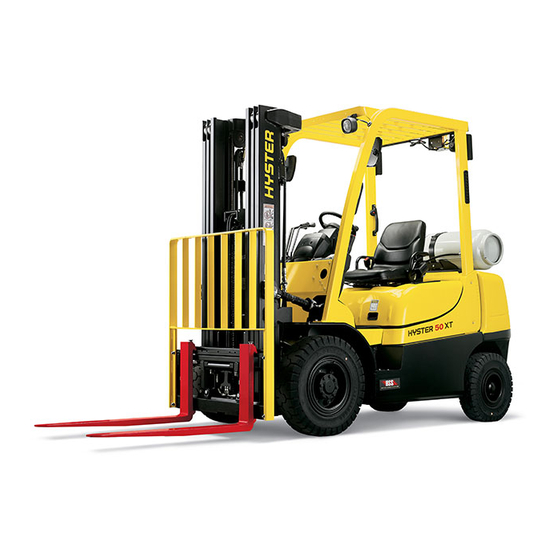
Page 11: Model Description
Model Description Model Description Figure 1. Model View Showing Major Components of H40-60XT... - Page 12 Model Description Legend for Figure 1 OVERHEAD GUARD CARRIAGE TAIL, BRAKE, AND REVERSE LIGHTS FORKS SEAT LOAD BACKREST EXTENSION COUNTERWEIGHT PARKING BRAKE STEERING AXLE STEERING WHEEL SEAT BELT AND HIP RESTRAINT MAST DRIVE AXLE OPERATING MANUAL (BEHIND SEAT)
-
Page 13: General
If a load These lift trucks are available with the following engine: backrest extension that is different from the one installed on your lift truck is required, contact your Hyster lift truck • PSI 2.4L engine which uses LPG fuel dealer. -
Page 14: Nameplate
2. If your lift truck has either of these labels, do not be undertaken without the written authorization of Hys- operate the lift truck. Contact your dealer for Hyster lift ter Company. trucks to obtain a complete correct Nameplate. -
Page 15: Safety Labels
Model Description Safety Labels Safety labels are installed on the lift truck to provide infor- mation about possible hazards. It is important that all safety labels are installed on the lift truck and can be read. See Figure 3. All possible label configurations that can be on the lift trucks covered in this Operating Manual are not shown in Figure 3. - Page 16 Model Description Figure 3. Warning and Safety Labels (Sheet 1 of 3)
- Page 17 Model Description Figure 3. Warning and Safety Labels (Sheet 2 of 3)
- Page 18 Model Description Figure 3. Warning and Safety Labels (Sheet 3 of 3)
-
Page 19: Controls
Model Description Legend for Figure 3 FLAMMABLE LP-GAS TRANSMISSION LABEL (EXAMPLE ONLY) NAMEPLATE LOCKING GAS SPRING NO ONE ON OR UNDER FORKS LPG TANK WARNING TIPOVER WARNING UL LABEL OVERHEAD GUARD LABEL ANTIFREEZE LABEL NO RIDERS BORON-FREE LABEL WARNING FOR PARKING BRAKE SPLIT WHEEL WARNING WARNING, OPERATION DIESEL FUEL LABEL (NOT SHOWN) - Page 20 Model Description Figure 4. Controls...
- Page 21 Model Description Legend for Figure 4 PARKING BRAKE LEVER TILT LEVER DIRECTION CONTROL LEVER 3RD AUXILIARY LEVER STEERING COLUMN TILT LEVER 4TH AUXILIARY LEVER STEERING WHEEL BRAKE PEDAL HORN INCHING/BRAKE PEDAL DASH DISPLAY ACCELERATOR PEDAL CONTROL BUTTON PANEL MONOTROL PEDAL KEY SWITCH MLM AUXILIARY HORN BUTTON LIGHT SWITCH/TURN SIGNAL...
- Page 22 Model Description Table 1. Controls Item Item Function Parking Brake to be on when lift truck is parked. Pull parking brake lever backward all the way to set it. Push the top button to release the lock, while pulling on the lever, and push lever for- ward to release parking brake.
- Page 23 Model Description Table 1. Controls (Continued) Item Item Function CAUTION This lift truck has a neutral switch. The engine will not start at a position other than neutral. Always change the shift lever from forward/reverse when the lift truck is stop- ped to protect the equipment and for safety.
- Page 24 Model Description Table 1. Controls (Continued) Item Item Function CAUTION Adjust the steering wheel when the lift truck is stopped, as adjustment during travel is dangerous. Adjust steering wheel as needed. Lever For Steering Column Tilt Lock Release Lock Steering Wheel The steering wheel controls the position of the steer tires.
- Page 25 Model Description Table 1. Controls (Continued) Item Item Function Horn The horn button controls the operation of the horn. Dash Display The screen shows icons for the warning and indicator lights. The display also shows operator messages for the different functions. All programmed warning and indicator lights will light up for two seconds (Start Check) when System Power is turned ON.
- Page 26 Model Description Table 1. Controls (Continued) Item Item Function NOTE: The key switch has a function of anti-restart, so if the engine does not start even when the key is turn to ST, return the key to OFF once, and then try again after 5 to 10 seconds.
- Page 27 Model Description Table 1. Controls (Continued) Item Item Function The light switch is integrated with the turn signal lever. When the switch is turned for- ward the light is turned ON. When the switch is turned backward the light is turned OFF.
- Page 28 Model Description Table 1. Controls (Continued) Item Item Function NOTE: If the operator is not in the seat or leaves the seat, hydraulic controls are not active to avoid unintentional movement of front end equipment. NOTE: Manual hydraulic control levers are standard on the trucks covered in this man- ual.
- Page 29 Model Description Table 1. Controls (Continued) Item Item Function Tilt Control NOTE: If the operator is not in the seat or leaves the seat, hydraulic controls are not Lever active to avoid unintentional movement of front end equipment. NOTE: Manual hydraulic control levers are standard on the trucks covered in this man- ual.
- Page 30 WARNING A manual control lever with a detent must be installed when an attachment with a clamp is installed. See your dealer for Hyster lift trucks to get the correct con- trol lever. NOTE: Manual hydraulic control levers are standard on the trucks covered in this man- ual.
- Page 31 Model Description Table 1. Controls (Continued) Item Item Function NOTE: If truck is equipped with only three levers and clamp attachments, the last (3rd) lever controls clamp functions. Control Lever with a Detent - Attachments with a clamp action:: The lever is spring-loaded toward the operator.
- Page 32 Model Description Table 1. Controls (Continued) Item Item Function NOTE: To operate the mini-levers, the operator must be on the seat. NOTE: If truck is equipped with only three levers and clamp attachment, the last (3rd) lever controls clamp functions. NOTE: Third lever on four function control cannot have clamping.
- Page 33 Model Description Table 1. Controls (Continued) Item Item Function NOTE: Manual hydraulic control levers are standard on the trucks covered in this man- ual. Optional electronic hydraulic mini-levers are available for the hydraulic functions. NOTE: If truck is equipped with four levers and clamp attachment, the last (4th) lever controls clamp functions.
- Page 34 Model Description Table 1. Controls (Continued) Item Item Function NOTE: To operate the mini-levers, the operator must be on the seat. NOTE: If truck is equipped with four levers and clamp attachment, the last (4th) lever controls clamp functions. NOTE: Third lever on four function control cannot have clamping. The last (4th) lever controls clamp functions.
- Page 35 Model Description Table 1. Controls (Continued) Item Item Function NOTE: The lift trucks covered in this Operating Manual may be equipped with optional electronic hydraulic mini-levers that are available for the hydraulic functions. NOTE: To operate the mini-levers, the operator must be on the seat. NOTE: If truck is equipped with a four function control valve with solenoid and clamp attachment, the last (4th) lever controls clamp functions.
- Page 36 Model Description Table 1. Controls (Continued) Item Item Function On lift trucks equipped with a four function control valve and solenoid for fifth function, the third lever controls both the third and fourth functions. To engage the fourth func- tion, toggle in the yellow override button located directly behind the third lever. To engage the third function toggle out the override button.
- Page 37 Model Description Table 1. Controls (Continued) Item Item Function Inching/ By varying the position of the inching/brake pedal, the operator can move the lift truck Brake slowly while a high engine speed is used for lifting loads. Completely depressing the Pedal pedal disengages the transmission and applies the service brakes.
- Page 38 Model Description Table 1. Controls (Continued) Item Item Function The auxiliary horn button functions when the key or keyless ignition is in the ON posi- tion and up to 20 minutes after the key or keyless ignition is turned to the OFF posi- tion.
- Page 39 Model Description Table 1. Controls (Continued) Item Item Function For lift trucks equipped with a Yanmar engine and traction speed limiter, this light will illuminate if the traction speed limiter is not working properly. Traction Speed Limiter Light...
- Page 40 Model Description Direction of Movement Function Load or Equipment Control Lever 1. REACH Retract/Extend Backward/Forward 2. SIDESHIFT Right/Left Backward/Forward 3. PUSH-PULL Backward/Forward Backward/Forward 4. ROTATE Clockwise/Counterclockwise Backward/Forward 5. UPENDER Up/Down Backward/Forward 6. SCOOP Up/Down Backward/Forward 7. LOAD STABILIZER Down (Clamp)/Up (Release) Backward/Forward 8.
-
Page 41: Dash Display
Model Description Dash Display may not contain all the warning and indicator lights shown in Figure 5 and Table 2. When the warning lights and indi- cators are on, the operator will see the appropriate symbol. WARNING When the warning lights and indicators are off, the operator If any of the instruments, levers, or pedals do not oper- will see a black panel. - Page 42 Model Description Figure 5. Dash Display - Warning and Indicator Lights...
- Page 43 Model Description Legend for Figure 5 FUEL GAUGE DISPLAY CHANGE BUTTON FOR HOUR METER SEDIMENTER (DIESEL ONLY) MODE CHANGE BUTTON ENGINE OIL PRESSURE CONTROL BUTTON PANEL GLOW LAMP COOLANT TEMPERATURE BATTERY CHARGE ALARM SET TORQUE CONVERTER OIL TEMPERATURE HOUR METER, CALENDAR WARNING CLOCK, SPEED, MESSAGE MAINTENANCE REQUIRED...
- Page 44 Model Description Table 2. Dash Display - Warning and Indicator Lights (See Figure 5) Item Item Function NOTE: There is no LPG fuel gauge or indicator light. When a lift truck with an LPG engine has low fuel, a warning buzzer beeps. This gauge indicates the amount of remaining fuel in the fuel tank.
- Page 45 Model Description Table 2. Dash Display - Warning and Indicator Lights (See Figure 5) (Continued) Item Item Function Engine Oil CAUTION Pressure Stop the engine immediately if this icon is ON while the engine is running. This icon is ON when the key switch is in the ON position and must go OFF when the engine is running.
- Page 46 Model Description Table 2. Dash Display - Warning and Indicator Lights (See Figure 5) (Continued) Item Item Function Display Each time you press a button the display changes to show operating information about Change But- the truck. Each screen will show either the date and the hours recorded on that date, ton - Center or a fault and the hourmeter reading at which it occurred.
- Page 47 Model Description Table 2. Dash Display - Warning and Indicator Lights (See Figure 5) (Continued) Item Item Function Mode Change Pressing this button at the same time as the Display Change Buttons will activate a Button different item on the display for adjustment. The item will blink until changed. Pressing this button once will return the display to normal mode.
- Page 48 Model Description Table 2. Dash Display - Warning and Indicator Lights (See Figure 5) (Continued) Item Item Function CAUTION Do not continue to operator the lift truck when the gauge indicates that the engine is too hot (full bars indicated, and warning buzzer beeping). This gauge indicates the temperature of the engine cooling water.
- Page 49 Model Description Table 2. Dash Display - Warning and Indicator Lights (See Figure 5) (Continued) Item Item Function Seat Belt WARNING Always fasten the seat belt when operating the lift truck. The icon flashes for 10 seconds anytime the key switch is put in the ON position. If the seat belt interlock option is equipped, the icon goes OFF immediately after fastening the seat belt.
-
Page 50: Operating Procedures
Operating Procedures Operating Procedures General If engines are operated in confined spaces, maintain adequate ventilation or vent exhaust to the outside. Do Know Your Lift Truck not exceed applicable air contaminant limits (see 29 CFR 1910.1000 Table Z-1). WARNING Follow the inspection and maintenance schedule and Always make sure the parking brake is fully applied procedures in this manual. - Page 51 The fork lift truck is designed to pickup, move, and tier eign materials. Contact your local Hyster dealer for materials. The basic lift truck has a lift mechanism and forklift modifications that may be appropriate in envi- forks on the front to engage the load.
-
Page 52: Stability And Center Of Gravity
Operating Procedures This basic principle is used for picking up a load. The ability ted forward and back. The CG moves up and down as the of the lift truck to handle a load is discussed in terms of mast moves up and down. center of gravity and both forward and side stability. -
Page 53: Capacity (Weight And Load Center)
Operating Procedures truck, as well, because an unloaded truck will tip over to Capacity (Weight and Load Center) the side easier than a loaded truck with its load in the low- The capacity of the lift truck is shown on the Nameplate. ered position. -
Page 54: Inspection Before Operation
Operating Procedures The load center of a load is determined by the location of its center of gravity. The load center is measured from the Checks With the Engine Stopped front face of the forks, or the load face of an attachment, to the center of gravity of the load. -
Page 55: Mounting And Dismounting
Operating Procedures • Fuel level. Lift Truck Interlocks • Oil level in the engine. Certain operator actions, if not performed correctly while operating the lift truck, will cause traction and the hydraulic • Oil level in the hydraulic tank. functions to become disabled. •... -
Page 56: Starting Procedure
Operating Procedures hydraulic function will be enabled and the operator can 3. Put direction control lever for transmission in NEUTRAL continue to load and unload material. position. Starting Procedure 4. Make sure lift truck hood is closed. 5. Turn key to the ON position. If lift truck is equipped with DO NOT start or operate the lift truck, a diesel engine and engine is cold, the cold start indicator including any of its functions or attach-... -
Page 57: Checks With The Engine Running
Operating Procedures stantially within the confines of the truck frame and over- head guard if a tipover occurs. This protection system is Checks With the Engine Running intended to reduce the risk of the head and torso being trapped between the truck and the ground, but it can not WARNING protect the operator against all possible injury in a tipover. -
Page 58: Operating Techniques
Operating Procedures • Check the operation of the steering system. comes to a sudden stop, the locking mechanism will be activated and hold the operator's lower torso in the seat. • Check the oil level in the transmission when the oil is at operating temperature 50 °C (120 °F). - Page 59 Operating Procedures through several driving and load handling operations before rail, toe board, and screen or shield at least 2 m (7 ft) the operator attempts to operate the lift truck alone. A basic high between the people on the platform and the lift education in proper driving and load handling techniques is mechanism.
- Page 60 Operating Procedures 3. ADJUST SEAT - STANDARD FULL SUSPENSION. • The handle can be turned counterclockwise to increase or clockwise to decrease the weight resistance, pull han- Seat Position Adjustment dle out before turning. As the handle is turned, the "stiff- •...
- Page 61 Operating Procedures • The target is for the "ride indicator" to fall between the • The handle can be turned as shown to increase or arrows when opertaor sits upright in seat with feet posi- decrease weight resistance. Pull handle out before turn- tioned on pedals.
- Page 62 Operating Procedures Figure 6. Seat Adjustment...
-
Page 63: Driving And Direction Changes
Operating Procedures Legend for Figure 6 STANDARD FULL SUSPENSION SEAT PREMIUM FULL SUSPENSION SEAT STANDARD NON-SUSPENSION SEAT HIP RESTRAINT WEIGHT ADJUSTMENT KNOB SEAT BELT BACKREST ANGLE ADJUSTMENT LEVER FORWARD/BACKWARD ADJUSTMENT LEVER RIDE POSITION INDICATOR 5. DO NOT drive a lift truck into an elevator unless author- 6. -
Page 64: General
Operating Procedures Table 3. Transmissions (Continued) REVERSE. If the lift truck has a Direction Control Switch, rock the switch toward the palm rest to go FORWARD and Basic Powershift or toward the base to go in REVERSE. If the truck has a Operational Feature Electronic Power- direction control lever, move the lever toward the front of... -
Page 65: Standard Operator Presence System
Operating Procedures Standard Operator Presence System tor leaves the seat of the lift truck with the engine running and without applying the parking brake. WARNING Basic Powershift or Electronic Powershift Always make sure the parking brake is fully applied Transmission before leaving the lift truck. -
Page 66: Inching Control
Operating Procedures CAUTION The drive train can be damaged if the lift truck is travel- ing too fast when the controls are changed to the opposite direction of travel. The operator can change the direction of travel at slow travel speeds (less than a walking speed), but the mast must not be in a raised position. -
Page 67: Steering (Turning)
Operating Procedures Steering (Turning) ground will aggravate these conditions and cause the fork- lift to become unstable. WARNING WARNING TRAVEL SLOWLY WHEN TURN- Failure to observe the tail swing area when making a ING. Lift trucks can tip over even turn can injure or kill someone. -
Page 68: Load Handling, General
Operating Procedures the tail swing area when making a turn can lead to injury or Load Handling, General death. 1. The capacity is the maximum DO NOT turn on an incline. To load that the lift truck can handle for reduce the possibility of a tipover, a the load condition shown on the lift truck must not be driven across... - Page 69 Operating Procedures WARNING If the fork/locking pin is not fully engaged, the fork could become unintentionally disengaged. 3. Position each fork the same distance from the center of the carriage. This action will help center the load on the carriage. Set the forks as far apart as possible for maxi- mum support of the load.
-
Page 70: Load Handling, Lifting, Lowering, And Tilting
DO NOT lift or hit anything that can fall on the operator or a bystander. Remember, a lift truck equipped with a Hyster overhead guard and load backrest extension provides rea- sonable protection to the operator from falling objects, but can not protect against every possible impact. - Page 71 Operating Procedures lift mechanism has moving parts with close clearances WARNING that can cause serious injury. Lift and lower with the mast vertical or tilted slightly back- ward from vertical. Tilt elevated loads forward only when directly over the unloading place. Keep yourself and all others clear of the lift mecha- nism.
-
Page 72: Load Handling, How To Engage And Disengage A Load
Operating Procedures If the lift mechanism is raised to pick up or deposit a load, Load Handling, How to Engage and keep the tilt angle in either direction to a minimum. Back- Disengage a Load ward and forward tilt are helpful, but they affect side and forward stability. - Page 73 Operating Procedures 2. Move forward slowly until the forks are in position under mast backward just far enough to lift the load from the sur- the load. The forks must support at least two-thirds (2/3) of face. the length of the load. Make sure that the load is centered between the forks.
- Page 74 Operating Procedures 4. If the load is being removed from a stack, slowly move placed. DO NOT raise the load to a point below where the the lift truck away from the stack. When the load is clear of load is to be placed and "jog" the load up into position. This the stack, lower the load for traveling.
-
Page 75: Load Handling, Traveling
Operating Procedures IF THE LIFT TRUCK TIPS OVER EITHER TO THE SIDE NOTE: Not every load can be lifted using only the forks of a OR FORWARD, DO NOT JUMP OFF! HOLD FIRMLY TO lift truck. Some loads will require a special attachment. STEERING WHEEL, BRACE YOUR FEET, AND LEAN 6. - Page 76 Operating Procedures Always look in the direction of travel to avoid damage to something or injury to someone. 3. For better visibility with large loads, travel with the load trailing, but always keep a proper lookout in the direction of travel.
- Page 77 Operating Procedures 6. Anytime the lift truck is moving keep arms, legs, etc., inside the operator's compartment. Arms and legs outside the machine can be injured when passing obstructions. 7. Avoid bumps, holes, mud, slick When operating an unloaded lift truck on a grade in spots, and loose materials that excess of 5%, keep the counterweight upgrade.
- Page 78 Operating Procedures 8. Watch clearances, especially forks, mast, overhead guard, and tail swing. A lift truck is designed to perform a wide variety of functions within limited space. 9. DO NOT indulge in stunt driving or horseplay. The operator must be aware that the forks can sometimes extend beyond the front of the load.
-
Page 79: Set Up The Load Weight Sensor
Operating Procedures run off the edge of the travel surface onto soft ground, the stored as a zero value of load weight sensor. Each HEX bit lift truck can tip over. is equivalent to about 7 kg (2.2 lb). To calculate weight stored for zero value, convert A/D value from HEX to decimal format, then multiply by 7. -
Page 80: Load Meter
Operating Procedures 11. Press ◄ until LoOO kG - SET nnn displays. Load Meter 12. Raise forks 30 to 40 mm (12 to 16 in.). Your lift truck may be equipped with an optional load meter. The load meter calculates mast pressure and converts that 13. -
Page 81: Highway Trucks, Rail Cars, And Docks
Operating Procedures 5. Rev engine and lift forks 30 to 50 cm (11.8 to 19.7 in.) Highway Trucks, Rail Cars, and Docks from floor. WARNING 6. After several second Lo 0kg Set XXX will appear 0kg set Maintain a safe distance from the is complete. -
Page 82: Attachments
Operating Procedures • DO NOT use a lift truck to open or close the door on a • Make sure that the rail cars brakes are set and the rail cars unless the lift truck has an attachment that is wheels are blocked while loading or unloading. -
Page 83: Disconnecting Attachment Hydraulic Quick-Disconnect Hoses
Operating Procedures 2. Disconnect the negative terminal of the battery. 3. Move the manual hydraulic levers forward and backward to relieve the system hydraulic pressure. 4. Disconnect the Quick-Disconnect hose connections. See Figure 9. Connecting Attachment Hydraulic Quick- Disconnect Hoses 1. - Page 84 Operating Procedures QUICK-DISCONNECT FITTINGS HYDRAULIC TUBES Figure 9. Quick-Disconnect Hoses Connections...
-
Page 85: Stopping
Operating Procedures Stopping 4. Turn the key to the OFF position to stop the engine. 5. To release seat belt, press red release button and guide belt carefully back into retractor with your hand. 6. If the lift truck must be left on an incline, put blocks on the down hill side of the wheels so that the lift truck can not move. -
Page 86: Maintenance
• Intensive usage at high performance levels on other abnormal conditions will require more frequent servicing. CAUTION Your dealer for Hyster lift trucks has the equipment and Disposal of lubricants and fluids must meet local envi- trained service personnel to do a complete program of ronmental regulations. -
Page 87: Serial Number Data
Maintenance Schedule. Service Manuals are available slope will also make the lift truck more difficult to stop. from your dealer for Hyster lift trucks to help users who do Never lift and move a disabled lift truck unless the dis- their own maintenance. -
Page 88: How To Put A Lift Truck On Blocks
Maintenance around a mast crossmember and the carriage, to prevent Before removing the mast and drive axle, put carriage and mast channels from moving. blocks under the counterweight so that the lift truck cannot fall backward. 4. If another lift truck is used to tow the disabled lift truck, that lift truck must have an equal or larger capacity than the Before removing the counterweight, put blocks disabled lift truck. -
Page 89: How To Raise The Steering Tires
Maintenance 4. Put additional blocks under the frame behind the drive 2. Use a hydraulic jack to raise the steering tires. Make tires. sure that the jack has a capacity of at least 2/3 of the total weight of the lift truck as shown on the Nameplate. 5. - Page 90 Maintenance DRIVE TIRES STEERING TIRES Figure 10. Put a Lift Truck on Blocks...
-
Page 91: How To Clean A Lift Truck
Maintenance Schedule How to Clean a Lift Truck battery area, and dash display during the cleaning process. CAUTION Portions of your lift truck may be washed with a non-heated Your lift truck may be damaged if water or cleaning pressure washer. Steam cleaning is not recommended in agents come in contact with electrical components. - Page 92 Maintenance Schedule Figure 11. Maintenance and Lubrication Points, PSI 2.4L LPG Trucks...
- Page 93 Maintenance Schedule Figure 12. Maintenance and Lubrication Points, Yanmar 2.6L and 3.3L Diesel Trucks...
- Page 94 Maintenance Schedule Figure 13. Maintenance and Lubrication Points, PSI 2.4L Bi-Fuel Trucks...
- Page 95 Maintenance Schedule Maintenance Schedule (See Figure 11, Figure 12, and Figure 13.) 8 Hr/ 250 Hr/ 500 Hr/ 1000 Hr/ 2000 Hr/ 4000 Hr/ Procedure or Item No. Item Specification 1 Day 6 Mo 6 Mo 6 Mo 1 Yr 2 Yr Quantity TIRES AND WHEELS...
- Page 96 Maintenance Schedule 8 Hr/ 250 Hr/ 500 Hr/ 1000 Hr/ 2000 Hr/ 4000 Hr/ Procedure or Item No. Item Specification 1 Day 6 Mo 6 Mo 6 Mo 1 Yr 2 Yr Quantity ENGINE COMPARTMENT Remove Combustible Materials. See NOTE 5. CHECK FOR LEAKS - Check for FUEL, OIL, WATER...
- Page 97 Maintenance Schedule 8 Hr/ 250 Hr/ 500 Hr/ 1000 Hr/ 2000 Hr/ 4000 Hr/ Procedure or Item No. Item Specification 1 Day 6 Mo 6 Mo 6 Mo 1 Yr 2 Yr Quantity SERVICE BRAKES Check Lining 1.0 mm (0.04 in.) Mini- Thickness.
- Page 98 Maintenance Schedule 8 Hr/ 250 Hr/ 500 Hr/ 1000 Hr/ 2000 Hr/ 4000 Hr/ Procedure or Item No. Item Specification 1 Day 6 Mo 6 Mo 6 Mo 1 Yr 2 Yr Quantity TRANSMISSION OIL 8.3 liter John Deere (8.8 qt) JDM J20C TRANSMISSION OIL 1 Filter...
- Page 99 Maintenance Schedule 8 Hr/ 250 Hr/ 500 Hr/ 1000 Hr/ 2000 Hr/ 4000 Hr/ Procedure or Item No. Item Specification 1 Day 6 Mo 6 Mo 6 Mo 1 Yr 2 Yr Quantity ENGINE OIL 4.9 liter –7 °C (20 °F) and Below PSI Engine (5.2 qt) SAE 5W-20...
- Page 100 Maintenance Schedule 8 Hr/ 250 Hr/ 500 Hr/ 1000 Hr/ 2000 Hr/ 4000 Hr/ Procedure or Item No. Item Specification 1 Day 6 Mo 6 Mo 6 Mo 1 Yr 2 Yr Quantity ENGINE OIL FILTER 1 Filter See Parts Manual. Yanmar Engine See NOTE 4 and NOTE 5.
- Page 101 Maintenance Schedule 8 Hr/ 250 Hr/ 500 Hr/ 1000 Hr/ 2000 Hr/ 4000 Hr/ Procedure or Item No. Item Specification 1 Day 6 Mo 6 Mo 6 Mo 1 Yr 2 Yr Quantity ENGINE IDLE SPEED 850 ±25 RPM PSI Engine ENGINE GOVERNED 2700 ±25 RPM SPEED (No Load)
- Page 102 Maintenance Schedule 8 Hr/ 250 Hr/ 500 Hr/ 1000 Hr/ 2000 Hr/ 4000 Hr/ Procedure or Item No. Item Specification 1 Day 6 Mo 6 Mo 6 Mo 1 Yr 2 Yr Quantity TIMING Adjust as Preset at 6° ATDC Yanmar 3.3L Engine Required.
- Page 103 Maintenance Schedule 8 Hr/ 250 Hr/ 500 Hr/ 1000 Hr/ 2000 Hr/ 4000 Hr/ Procedure or Item No. Item Specification 1 Day 6 Mo 6 Mo 6 Mo 1 Yr 2 Yr Quantity SPARK PLUGS Change Torch P/N DK7RTC PSI Engine Spark Plugs.
- Page 104 Maintenance Schedule 8 Hr/ 250 Hr/ 500 Hr/ 1000 Hr/ 2000 Hr/ 4000 Hr/ Procedure or Item No. Item Specification 1 Day 6 Mo 6 Mo 6 Mo 1 Yr 2 Yr Quantity LIFT CHAINS L, X Check for Engine Oil Wear.
- Page 105 Lower Hook Capscrews 8 Capscrews TILT CYLINDER ENDS 4 Fittings Multipurpose Grease See NOTE 7. BRAKE MASTER Use Silicone Spray CYLINDER ROD Hyster Part No. 328388. END PIN MANUAL HYDRAULIC API SM HAND LEVERS ILSAC GF4 SAE J2362 BRAKE FLUID 0.2 liter...
- Page 106 Wheel Bearings Grease. See NOTE 7. PEDALS, LEVERS, SEAT Lubricate as Use Silicone Spray RAILS, CABLES, HINGES, Necessary. Hyster Part No. 328388. LINKAGES PARKING BRAKE Adjust as Must hold a Full Capacity ADJUSTMENT Necessary. Load on a 15% Grade. PARKING BRAKE...
- Page 107 Maintenance Schedule 8 Hr/ 250 Hr/ 500 Hr/ 1000 Hr/ 2000 Hr/ 4000 Hr/ Procedure or Item No. Item Specification 1 Day 6 Mo 6 Mo 6 Mo 1 Yr 2 Yr Quantity INSPECT ENGINE VACUUM AND FUEL LINES AND FITTINGS INSPECT LOCK-OFF FOR LEAKS AND ENSURE LOCK-OFF CLOSING...
- Page 108 (dust and waste paper); chemical or abrasive compounds; poor ground conditions; intensive usage at high perform- ance levels; or other abnormal conditions will require more frequent servicing. At your request, your Hyster dealer will advise you of the appropriate serv- ice intervals based on an application survey.
- Page 109 Maintenance Schedule 8 Hr/ 250 Hr/ 500 Hr/ 1000 Hr/ 2000 Hr/ 4000 Hr/ Procedure or Item No. Item Specification 1 Day 6 Mo 6 Mo 6 Mo 1 Yr 2 Yr Quantity NOTE 12: Hydraulic oil sampling and analysis is a recommended practice. See Hydraulic Cleanliness Procedures 1900 SRM 1620 for oil cleanliness and water content guidelines.
-
Page 110: Maintenance Procedures Every 8 Hours Or Daily
Maintenance Maintenance Procedures Every 8 Hours or Daily How to Make Checks With the Engine normal. Clean any oil or fuel spills. Ensure all surfaces are free of oils, lubricants, fuel and organic dust or fibers Stopped (paper, wood, cotton, agricultural grass/grain, etc.). WARNING Tires and Wheels DO NOT operate a lift truck that needs repairs. - Page 111 Maintenance CHECK FOR DAMAGE (REMOVE NAILS, GLASS AND OTHER OBJECTS FROM THE TREAD) MAKE SMOOTH EDGES CHECK THE TIRE PRESSURE (PNEUMATIC TIRES) Figure 14. Check the Tires...
-
Page 112: Safety Labels
Maintenance Safety Labels DO NOT try to correct the alignment of the fork tips by bending the forks or adding shims. If either fork is damaged, replace the forks as a set. WARNING Safety labels are installed on the lift truck to give infor- Never repair damaged forks by heating or welding. - Page 113 Maintenance sure the parts that fasten the sideshift carriage or attach- ment to the carriage are in good condition. 6. Visually inspect hoses/fittings for hydraulic leaks; hose cover for cuts, cracks, or exposed reinforcement; defective/ broken clamping devices or sheaves; and proper tracking during operation.
-
Page 114: Operator Restraint System
Maintenance Operator Restraint System and Figure 17). Each item must be checked to make sure it is fastened correctly, functions correctly, and is in good The seat belt, hip restraint, seat, hood, and hood latches condition. are all part of the operator restraint system (see Figure 16... - Page 115 Maintenance Figure 16. Seat Check...
- Page 116 Maintenance Legend for Figure 16 STANDARD FULL SUSPENSION SEAT PREMIUM FULL SUSPENSION SEAT STANDARD NON-SUSPENSION SEAT HIP RESTRAINT WEIGHT ADJUSTMENT KNOB SEAT BELT BACKREST ANGLE ADJUSTMENT LEVER FORWARD/BACKWARD ADJUSTMENT LEVER RIDE POSITION INDICATOR...
- Page 117 Maintenance LATCH STRIKER BUMPER HOOD HOOD RELEASE HANDLE HOOD LATCH LIFT TRUCK FRAME BOOT Figure 17. Hood and Hood Latch Check...
-
Page 118: Emergency Locking Retractor (Elr)
Maintenance Emergency Locking Retractor (ELR) pulled from the retractor assembly or the belt will not retract, replace the seat belt assembly. When the ELR style seat belt is properly buckled across the operator, the belt will permit slight operator reposition- •... -
Page 119: Engine Compartment
Maintenance Engine Compartment place and in contact with the ground. Check attaching hard- ware. If worn, missing or not in contact with the ground, Check for the presence of any combustible material such replace strap and mounting hardware as required. as paper, leaves etc. - Page 120 Maintenance FRAME GROUND STATIC STRAP BATTERY Figure 18. Ground Static Strap...
-
Page 121: Fuel, Oil, And Coolant Leaks, Check
Maintenance Fuel, Oil, and Coolant Leaks, Check Hydraulic Hoses Check the condition of the hydraulic hoses for serviceability WARNING by inspecting for cracks or other obvious damage. Check to All fuels are very flammable and can burn or cause an insure that the hydraulic hoses are not leaking. -
Page 122: Hydraulic System Oil
Maintenance Hydraulic System Oil WARNING At operating temperature the hydraulic oil is HOT. Do not permit the hot oil to touch the skin and cause a burn. CAUTION DO NOT permit dirt to enter the hydraulic system when the oil level is checked or the filter is changed. Never operate the hydraulic pump without oil in the hydraulic system. -
Page 123: Engine Oil
Maintenance Legend for Figure 19 There is an indicator light for the engine oil pressure on the Dash Display. During normal operation the red indicator DIPSTICK BREATHER/FILLER NECK light will illuminate when the key switch is turned to ON and RETURN FILTER RIGHT FRAME CHANNEL will stay illuminated until correct oil pressure is obtained, at... - Page 124 Maintenance BATTERY AUXILIARY COOLANT RESERVOIR DRIVE BELT RADIATOR CAP AIR FILTER FUEL FILTER DIPSTICK ENGINE OIL ENGINE OIL FILTER ENGINE OIL FILL FUEL INJECTOR Figure 20. Yanmar 2.6L Diesel Engine Maintenance Points...
- Page 125 Maintenance BATTERY DRIVE BELT RADIATOR CAP AUXILIARY COOLANT RESERVOIR AIR FILTER ENGINE OIL FILTER FUEL FILTER DIPSTICK ENGINE OIL FUEL INJECTOR ENGINE OIL FILL Figure 21. Yanmar 3.3L Diesel Engine Maintenance Points...
- Page 126 Maintenance BATTERY PCV VALVE SPARK PLUGS DRIVE BELT ENGINE OIL FILL RADIATOR CAP AUXILIARY COOLANT RESERVOIR FUEL FILTER ENGINE OIL FILTER AIR FILTER ENGINE OIL DRAIN PLUG DIPSTICK ENGINE OIL Figure 22. PSI 2.4L LPG Engine Maintenance Points...
- Page 127 Maintenance BATTERY PCV VALVE SPARK PLUGS ENGINE OIL FILL DRIVE BELT RADIATOR CAP LPG FUEL FILTER AUXILIARY COOLANT RESERVOIR ENGINE OIL FILTER AIR FILTER GASOLINE FUEL FILTER ENGINE OIL DRAIN PLUG DIPSTICK ENGINE OIL INJECTOR Figure 23. PSI 2.4L Bi-Fuel Engine Maintenance Points...
-
Page 128: Air Filter
Maintenance Air Filter ponents can occur if fork latch pins are not removed prior to using attachment. The air filter canister should not be opened until an air filter NOTE: Forks are to be replaced only in sets and not indi- element replacement is required. - Page 129 Maintenance OUTER FORK CARRIER FORKS INNER FORK CARRIER SIDESHIFT CARRIAGE FORK POSITIONER CAPSCREWS FORK REMOVAL NOTCH Figure 24. Fork Positioner Prior to December, 2016...
- Page 130 Maintenance OUTER FORK CARRIER FORKS INNER FORK CARRIER SIDESHIFT CARRIAGE FORK POSITIONER CAPSCREWS FORK REMOVAL NOTCH Figure 25. Fork Positioner After December, 2016...
-
Page 131: Forks, Inspect
Maintenance Forks, Inspect WARNING DO NOT try to correct for tip alignment by bending the forks or adding shims. Replace bent forks. Never repair damaged forks by heating or welding. Forks are made of special steel using special proce- dures. Replace damaged fork. Forks are to be replaced only in sets and not individually. - Page 132 Perform fork wear inspec- thickness of fork shank in Step a above. (e.g. for N 1.75 tion using a BOL256N1 caliper ruler Hyster P/N 4092984 use N 1.75 opening). This is typically the section of fork as follows.
- Page 133 Maintenance Fork Tip Alignment Length of Forks 3% Dimension 914 mm (36 in) 27 mm (1.08 in) 1016 mm (40 in) 30 mm (1.2 in) 1067 mm (42 in) 32 mm (1.26 in) 1207 mm (47.5 in) 36 mm (1.42 in) 1219 mm (48 in) 37 mm (1.46 in) 1372 mm (54 in)
-
Page 134: Forks, Install
Maintenance Forks, Install WARNING DO NOT try to move a fork without a lifting device. Each hook fork for these lift trucks can weight 45 to 115 kg (99 to 253 lb). CAUTION Remove fork latch pins if adding a fork positioner attachment. -
Page 135: Forks, Adjust
Maintenance 2. If lift truck is equipped with a fork positioner attachment, Forks, Adjust install inner fork carriers using four capscrews. Tighten cap- NOTE: During the adjustment of the forks, the heel of the screws to 35 N•m (25 lbf ft). See Figure 24 or Figure 25. forks should not be touching the ground. -
Page 136: Brake Fluid
Maintenance Brake Fluid Replace the brake fluid in the system if there is dirt or water in the system. WARNING On lift trucks with dry brakes, only use SAE J-1703 Small amounts of water in the brake system can cause (DOT 3) brake fluid in the master cylinder. - Page 137 Maintenance Figure 30. Brake Fluid Reservoir Cover...
-
Page 138: How To Make Checks With The Engine Running
Maintenance Legend for Figure 30 COVER CLOSED COVER OPEN COVER BRAKE FLUID RESERVOIR CAPSCREW MOUNTING BRACKET How to Make Checks With the Engine Be careful when making the checks. If the lift truck is sta- tionary during a check, apply the parking brake and put the Running transmission in NEUTRAL. - Page 139 Maintenance Figure 31. PDM Showing Fuses and Relays...
-
Page 140: Service Brakes
Maintenance Legend for Figure 31 NOTE: HOOD REMOVED FOR CLARITY. BATTERY REAR WORK LIGHT (20 AMP) POWER DISTRIBUTION MODULE (PDM) FRONT WORK LIGHT RELAY START RELAY BACKUP RELAY STARTER (30 AMP) BATTERY+ (25 AMP) RESISTOR (68 OHM) FRONT WORK LIGHT (20 AMP) IGNITION 3 RELAY BATTERY+ (20 AMP) TRANZORB... -
Page 141: Parking Brake
Additives may damage the cooling system. Before obtained, at which time the light will go off. If the light con- using additives, contact your local Hyster dealer. tinues to stay on when the engine is running, the engine oil... - Page 142 Maintenance If coolant is added, use the correct mixture of water and ethylene glycol shown in the Maintenance Schedule. WARNING Compressed air can move particles so that they cause injury to the user or to other personnel. Make sure that the path of the compressed air is away from all person- nel.
-
Page 143: Steering System
Maintenance Steering System parts of the mast are completely lowered and the engine is STOPPED. WARNING If the mast cannot be lowered, use chains on the mast The lift truck has hydraulic power steering. The steer- weldments and carriage so that they can not move. ing can be difficult if the engine is not running. -
Page 144: How To Add Fuel To The Lift Truck
Maintenance 4. Raise the mast 1 m (3 ft) with a capacity load. The inner All fuels for internal combustion engines are very flam- weldments and the carriage must raise smoothly. Lower mable. the mast. All moving components must lower smoothly. Fill the fuel tank only in a designated area with good 5. -
Page 145: Lpg Tank, Removal
Maintenance Frost on the surface of the tank, the valves or fittings motor vehicles, electrical equipments, or ignition and the odor of LPG fuel indicates a leak. Inspect the source. LPG system and repair a leak immediately. An LPG fuel Removable LPG tanks must be removed from the fork leak creates an explosion and fire hazard. - Page 146 Maintenance NOTE: Lift trucks covered in this manual may be equipped 5. Unlatch the tank strap and remove the LPG tank from with a steel LPG tank strap. the bracket.
- Page 147 Maintenance NOTE: FABRIC TANK STRAP SHOWN. LPG TANK TANK STRAP QUICK DISCONNECT FITTING HYDROSTATIC RELIEF VALVE LPG BULKHEAD BRACKET FITTING HOSE ASSEMBLY LPG TANK BRACKET LPG TANK PIN TANK LATCH Figure 33. LPG Tank and Bracket...
-
Page 148: Lpg Tank, Fill
Maintenance LPG Tank, Fill hose to this fitting. Make sure the correct adapter is used to connect the supply hose to the auxiliary fill fitting. WARNING 5. Open the vent valve on the liquid level indicator. Read and follow all the refueling precautions and instructions under Liquefied Petroleum Gas (LPG). -
Page 149: Lpg Tank, Install
Maintenance LPG Tank, Install b. Smell - LPG has a very distinctive odor. If you smell LPG, DO NOT start the engine. WARNING c. Soapy Water - This method is used in conjunction Make sure the alignment pin extends through the cor- with Step b above. -
Page 150: Wheels And Tires
General equal to the Nameplate listed ply rating may be accept- able. Check with your Hyster dealer whether a specific This series of lift trucks have pneumatic tires or solid rubber bias-ply tire is approved for use on Hyster trucks. -
Page 151: Remove Tire From Wheel
3. Remove the wheel nuts and remove the wheel and tire Hyster trucks. from the lift truck. Lift truck tires and wheels are heavy. 1. Put the lift truck on blocks as described in How to Put a Remove Tire From Wheel Lift Truck on Blocks at the beginning of this section. - Page 152 Maintenance TWO-PIECE WHEEL THREE-PIECE WHEEL OPTIONAL RIM ASSEMBLY FOUR-PIECE WHEEL WHEEL RIM LOCK RING SIDE FLANGE FLANGE SEAT Figure 34. Types of Pneumatic Wheels...
-
Page 153: Tire Removal, Two-Piece Wheel
Maintenance Tire Removal, Two-Piece Wheel WARNING Make sure all of the air pressure is removed from the tire before a wheel is disassembled. Air pressure in the tires can cause the tire and rim parts to explode caus- ing serious injury or death. Keep tire tools in firm contact with the wheel parts. -
Page 154: Tire Removal, Three- And Four-Piece Wheels
Maintenance Tire Removal, Three- and Four-Piece Wheels 2. Put the tire tool into the slot between the lock ring and wheel WARNING rim. Remove the lock ring and side flange. If there is a flange Make sure all of the air pressure is removed from the tire before a wheel is disassembled. -
Page 155: Install Wheel In Tire
Maintenance 4. Remove the wheel rim from the • DO NOT mix types of tires, type of tire tread, or tire. wheel assemblies of different manufacturers on any one lift truck. DO NOT use a steel hammer on the wheel. Use a rub- ber, lead, plastic, or brass hammer to put parts together. -
Page 156: Tire Installation Three- Or Four-Piece Wheel
Maintenance • DO NOT mix parts between different types or manu- WARNING facturers of wheels. DO NOT lubricate the tire bead with antifreeze or petro- • DO NOT mix types of tires, type of tire tread, or leum-based liquid. Vapors from these liquids can wheel assemblies of different manufacturers on any cause an explosion during inflation or use. -
Page 157: Tire Installation Two-Piece Wheel
Maintenance 2. Install the wheel rim in the 4. Put the lock ring in the correct tire. Make sure the stem of the position on the rim. Add air pres- inner tube is aligned with the sure to the tire as described in slot in the rim. -
Page 158: Add Air To Pneumatic Tires With Tube
Maintenance 2. Tighten the nuts that hold the 1. Put the tire in a safety cage. See Figure 35. rim halves together to 175 N•m 2. Add 20 kPa (3 psi) of air pressure to the tire. (130 lbf ft). Add air pressure to the tire as described in Add Air 3. -
Page 159: Install The Wheels
Maintenance 5. Check that all wheel parts are correctly installed. If instal- the first position where the cotter pin can be installed. lation is not correct, remove all of the air pressure from the Install cap for bearings. tire. Remove the valve core to make sure all of the air pres- Pneumatic Tubeless Tire, Repair sure has been removed and then make adjustments. -
Page 160: Remove Tire From Wheel
Maintenance airtightness of the existing wheel and the tubeless tire 1. If wheel rim is a three- or assembly. See Figure 34. four-piece rim, turn the valve 1/4 turn and remove valve 1. Put the lift truck on blocks as described in How to Put a from wheel. -
Page 161: Install Tire On Wheel
Maintenance 3. Remove the loose flange 5. Push the TBS toward the locking ring and the advance inside of the tire to remove it. band (four-piece wheel only) using a tire tool. 4. Remove the press and Install Tire on Wheel remove the loose flange lock- ing ring and the advance WARNING... - Page 162 Maintenance • DO NOT mix parts between different types or manu- 1. Clean interior and exte- facturers of wheels. rior bead area of the tire. Lubricate tire beads and • DO NOT mix types of tires, type of tire tread, or the inside of the tire, up to wheel assemblies of different manufacturers on any the tire shoulders.
- Page 163 Maintenance 2. Apply lubricant to the nee- 4. Apply lubricant to the rim. If a four-piece wheel is being dle valve and the valve hole used, lubricate the advance band. Slide the tire and TBS that will be used (see NOTE onto the wheel.
- Page 164 Maintenance 5. Place the wheel and tire 7. Position the advance band. Ensure that it does not go in assembly on a flat surface. too far and damage the valve. Position the arms of the Turn the valve a 1/4 turn to press onto the loose flange.
-
Page 165: Add Air To Pneumatic Tubeless Tire
Maintenance Add Air to Pneumatic Tubeless Tire WARNING Add air pressure to the tires only in a safety cage. See Figure 36. Inspect the safety cage for damage before use. When air pressure is added, use a chuck that fas- tens onto the valve stem. -
Page 166: Solid Rubber Tires On Pneumatic Wheels, Change
Maintenance The steering wheels are fastened to the spindle of the Remove Tire From Wheel steering axle with a large castle nut. Make sure inner and outer bearings are correctly lubricated with grease. Install WARNING inner bearing assembly and wheel on spindle. Install outer Keep tire tools in firm contact with the wheel. - Page 167 Maintenance 1. Put the wheel rim on the bed of the press. Put the cage in position on the tire. Use the press to push the tire away from the side flange. 3. Turn the tire over. Put a support under the wheel rim. Make sure the wheel rim is at least 150 to 200 mm (6 to 8 in.) from the bed of the press.
-
Page 168: Install Tire On Wheel
Maintenance • Make sure that all parts of the wheel are the correct parts for the wheel assembly. • DO NOT mix parts between different types or manu- facturers of wheels. • DO NOT mix type of tires, type of tire tread, or wheel assemblies of different manufacturers on any one lift truck. - Page 169 Maintenance 1. Lubricate the wheel rim 2. Put the wheel rim on the bed of the press. Put the tire and the inner surface of the over the wheel rim. Put the cage in position on the tire. Use tire with tire lubricant or the press to install the tire on the wheel rim.
-
Page 170: Operating Procedures For A New Or Rebuilt Engine
Maintenance and indicators for the correct operation during this first operating period. Check for leaks. 3. If the work conditions are slow and the loads are less than 50% of the truck capacity, a simulated work condition must be used during the first four hours of operation. Oper- ate the lift truck with a minimum load of 75% capacity. -
Page 171: Jump-Starting Using Another Lift Truck
To prevent possible arcing between the two lift trucks, the strength of the overhead guard. make sure that the lift trucks are not touching. See your dealer for Hyster lift trucks BEFORE perform- CAUTION ing any changes to the overhead guard. -
Page 172: Short-Term Storage
Maintenance the storage location determines what procedures you 1. Check lubricant and fluid levels. Completely fill the fuel should follow. tank. Make sure the coolant mixture will protect cooling sys- tem and engine to lowest temperature expected during Before placing any lift truck in storage, you must choose an storage. -
Page 173: Long-Term Storage
Maintenance 7. Check the tire pressure, if applicable. Make sure the tires 4. Spray exterior surfaces and frame with preservative have the correct pressure (see the Nameplate.) coating. 8. Clean the lift truck and engine compartment to prevent While the Lift Truck is in Storage corrosion. -
Page 174: How To Put Batteries In Storage
Maintenance How to Put Batteries in Storage 2. Neutralize and clean the battery. Clean with a solution of 100 grams (3.5 oz) of sodium bicarbonate (baking soda) Batteries are to be placed on a wooden pallet and stored in per 1 liter (0.25 gal) of water. a dry, moderately cool area. -
Page 175: How To Move A Lift Truck On Atransport
Maintenance 3. Clean the battery cables and terminals. Check the bat- WARNING tery voltage. If the voltage is not correct, charge battery. IF THE LIFT TRUCK FALLS OFF THE DOCK, DO NOT Connect battery cables to battery. JUMP OFF! HOLD FIRMLY TO STEERING WHEEL, 4. -
Page 176: Loading
Maintenance Loading 2. If the mast is mounted on the lift truck, fully lower the forks or carriage. Tilt the mast FORWARD until the tips of the forks touch the surface. WARNING The straps or chains used to fasten the lift truck to the 3. -
Page 177: Unloading
Maintenance Unloading corrected before use of the lift truck, see the Service Man- ual Periodic Maintenance 8000 SRM 2000 for proce- If components normally attached to the lift truck were dures. removed for transport, see the Service Manual for installa- Preparation After Transport tion procedures. - Page 178 NOTES...
- Page 179 Spacer 3/19 (12/18)(7/18)(12/17)(10/17)(5/17)(3/17)(1/17)(11/16)(10/16)(7/16)(5/16)(4/16)(3/16)
Need help?
Do you have a question about the H40-60XT and is the answer not in the manual?
Questions and answers