
Related Manuals for Bien Air CHIROPRO 3rd Gen Series


Summary of Contents for Bien Air CHIROPRO 3rd Gen Series
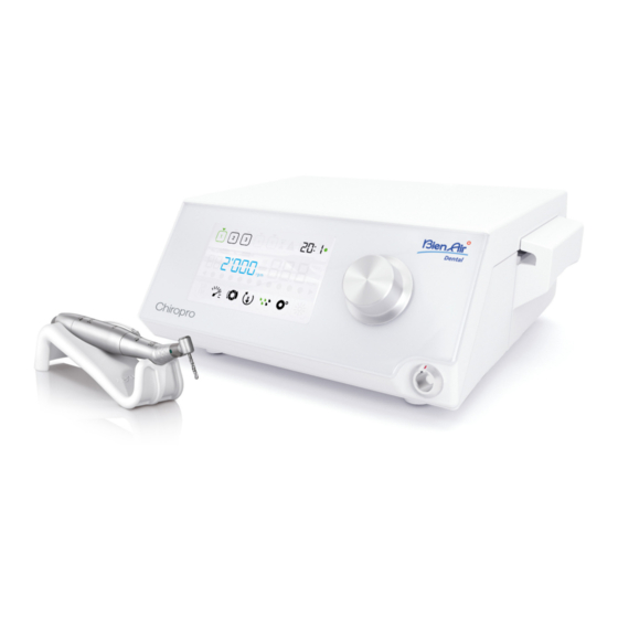
- Page 1 CHIROPRO 3 ENG INSTRUCTIONS FOR USE. Rx Only 0120 REF 2100318-0000/2018.10 © Bien-Air Dental...
- Page 2 Set Chiropro 3 Gen REF 1700708-001 REF 1600995-001 REF 1601008-001 REF 1601009-001 REF 1600631-001 REF 1500984-005 REF 1307727-010 REF 1303393-001 REF 1301575-001 REF 1502329-001 Set Chiropro 3 Gen CA REF 1700707-001 REF 1700708-001 REF 1600692-001 Set Chiropro 3 Gen KM REF 1700737-001 REF 1600995-001 REF 1601008-001 REF 1601009-001...
-
Page 3: Table Of Contents
Table of contents Symbols............. 2 Description of symbols for Chiropro 3 Gen units ....2 Description of symbols for Chiropro 3 Gen accessories ..2 Identification, Intended Use and Notation... 3 Identification ..................3 Intended use ..................3 Notation and chapter links ..............3 Warnings & Precautions of Use ....4 Description............ -
Page 4: Symbols
1 Symbols 1.1 Description of symbols for Chiropro 3 Gen units Symbol Description Symbol Description CE Marking with number of the notified body. Recyclable materials. Separate collection of electric and electronic Main switch - Power OFF. equipment. Main switch - Power ON. Manufacturer. -
Page 5: Identification, Intended Use And Notation
2 Identification, Intended Use and Notation 2.1 Identification 2.3 Notation and chapter links Electronically controlled tabletop device for dentistry allowing • A, B, C, etc. Text preceded by a letter indicates a procedure to be carried operation of a dental handpiece via an MX-i LED 3 out step-by-step. -
Page 6: Warnings & Precautions Of Use
3 Warnings & Precautions of Use CAUTION The power plug is used for disconnection in case of problems, it must be easily accessible at all times. CAUTION Never connect a handpiece on a running MX-i LED 3 micromotor. ... -
Page 7: Description
4 Description 4.1 Chiropro 3 Gen system overview FIG. 1 Peristaltic pump lid Button to start/stop irrigation Pedal connector (10) Foot control to reverse the rotation of the MX-i LED 3 Marking micromotor Bracket support (11) “Program” button to go to next operation step Main switch (12) Motor start Fuse box... -
Page 8: Sets Supplied
4.2 Sets supplied 4.3 Options Chiropro 3 Gen set REF 1700708-001 Designation REF number 3-button pedal 1600631-001 Designation REF number 1601008-001 1600995-001 MX-i LED 3 Gen micromotor Chiropro 3 Gen unit (1x) Contra-angle handpiece CA 20:1 L KM 1601008-001 MX-i LED 3 Gen micromotor (1x) 1600786-001 Micro-Series (light) -
Page 9: Environmental Protection And Information For Disposal
4.5 Environmental protection and Environmental Operating Transport and storage information for disposal conditions (max. 15 weeks) Relative humidity (including 30% to 80% 10% to 100% condensation) The disposal and/or recycling of materials must be performed in Atmospheric 700 hPa to 500 hPa to 1060 hPa accordance with the legislation in force. -
Page 10: Electromagnetic Compatibility - Emissions & Immunity
4.6.3 Electromagnetic compatibility – emissions & immunity Guidance and manufacturer’s declaration – Electromagnetic emissions The Chiropro 3 Gen is intended for use in the electromagnetic environment specified below. The customer or the user of the Chiropro 3 Gen must ensure that it is actually used in such an environment. Emissions test Compliance Electromagnetic environment - guidance... - Page 11 Electromagnetic Immunity test IEC 60601 test level Compliance level environment - guidance Field strengths from fixed RF transmitters, as deter- 0,15 MHz – 80 MHz 0,15 MHz – 80 MHz mined by an electromagne- Conducted disturbances induced by RF fields in ISM bands in ISM bands tic site survey...
-
Page 12: Installation
5 Installation FIG. 1 FIG. 2 FIG. 3 FIG. 4 AAAA-MM-JJ FIG. 5 FIG. 6 FIG. 7 FIG. 8 FIG. 9 FIG. 10 FIG. 11... -
Page 13: Install The Chiropro 3 Rd Gen System
FIG. 7 5.1 Install the Chiropro 3 Gen system I. Connect the flexible hose of the irrigation line to the spray tube of the handpiece or contra-angle. FIG. 1 FIG. 8 A. Place the Chiropro 3 Gen on a flat surface capable of bearing J. -
Page 14: Interface Overview
FIG. 1 FIG. 2 6 Interface overview 6.2 Rotating knob functions overview 6.1 Chiropro 3 Gen modes Note 2 The Chiropro 3 Gen allows to visualize and control operation parameters by the means of the LCD display. Knob action Description A unique screen allows to use the following modes: Increase current value, go to the element FIG. -
Page 15: Sound Alerts
FIG. 3 FIG. 4 6.3 Sound alerts NOTES The Operation mode is the default startup mode. Sound alert Description Activating irrigation, going to next step, Any knob or pedal action will be ignored when the motor is One short beep and switching rotation direction to running. -
Page 16: Operation
FIG. 1 FIG. 2 7 Operation 7.1 Operation screen description • Turn the knob CW or CCW to respectively increase or decrease the micromotor maximum reachable speed (quick FIG. 1 setting mode). The Operation screen differs whether the micromotor is stopped The speedometer is cyan and displays the set micromotor or running and depending on the active step. - Page 17 FIG. 3 FIG. 4 • Turn the knob CW or CCW to respectively increase or decrease the micromotor maximum reachable torque (quick setting mode). NOTES The torquemeter (3) turns cyan and displays the set micromotor maximum reachable torque. Note 11 Real-time speed value is displayed in black when the MX-i LED 3 Gen micromotor is running.
-
Page 18: Settings
FIG. 1 FIG. 2 8 Settings FIG. 1 8.2 MX-i LED 3 Gen micromotor torque The Settings mode allows changing all parameters of each step. It is accessed by long pressing the knob from the Operation mode A. From the Settings mode menu, select the symbol and and leaved by also long pressing the knob or by running the short press on the knob to change maximum reachable torque. -
Page 19: Irrigation Level
FIG. 3 FIG. 4 8.4 Irrigation level A. From the Settings mode menu, select the symbol and NOTES short press on the knob to change irrigation level. Note 1 The rotation direction and the irrigation level symbols differ FIG. 4 depending on the actual settings. -
Page 20: Special Modes
FIG. 1 FIG. 2 9 Special modes The special modes allow to, in the following order: Reverse torque boost value • Display software version; Reverse torque boost allows an automatic increase of torque • Test LCD display; value when in REVERSE mode, in order to ease bur rotation when •... - Page 21 FIG. 3 FIG. 4 NOTES Pressing the footpedal has no effect in the Special modes. Go through all the special modes to display the Settings mode again. The reset no text is displayed by default.
-
Page 22: List Of Errors & Troubleshooting
10 List of errors & Troubleshooting 10.1 Safety warning (operating) Warning description Message Cause of warning Action Excessive power demand of Motor overheating Avoid extended use. Let system cool down. the MX-i LED 3 Gen micro- motor. • Pedal is pressed when accessing settings sub- modes. -
Page 23: Device Operating Error
10.2 Device operating error Error description Cause of error When Action ERROR 1 Electrical failure: short-circuit Motor short-circuit In running mode. Replace motor and/or cable. between motor phases. ERROR 2 Other fault condition detected 1. Switch off system. Main controller error Any time. -
Page 24: Maintenance
FIG. 1 11 Maintenance CAUTION 11.3 Important Only use original Bien-Air Dental maintenance products and parts For maintenance: ........See instructions for use or those recommended by Bien-Air Dental. Using other products MX-i LED 3 Gen micromotor ....REF 2100245 or parts may cause operational failure and/or void the guarantee. Cable for micromotor......REF 2100163 Contra-angle CA 20:1 L, light....REF 2100209 11.1 Servicing... -
Page 25: Replacement Of Fuses
FIG. 2 FIG. 3 11.4 Replacement of fuses A. Switch off the Chiropro 3 Gen unit. NOTES B. Disconnect the mains cable. CAUTION Bien-Air Dental SA recommends the user to have its dynamic The power cable must be disconnected at least 10 seconds before instruments regularly checked or inspected. -
Page 26: General Information And Guarantee
12 General information and guarantee 12.1 General information The device must be used by qualified professionals in compliance with the current legal provisions concerning occupational safety, health and accident prevention measures, and these instructions for use. In accordance with such requirements, the operators: •... - Page 28 Bien-Air USA, Inc. Bien-Air UK Ltd Beijing Bien-Air Bien-Air Dental SA 5 Corporate Park Arundel House Medical Instrument Länggasse 60 Suite 160 Whitworth Road Technology Service Co. Ltd. Case postale Irvine, CA 92606 USA Crawley, West Sussex Room 1415, 2500 Bienne 6, Switzerland Phone +1 800-433-2436 RH11 7XL, England Block B Lucky Tower,...
Need help?
Do you have a question about the CHIROPRO 3rd Gen Series and is the answer not in the manual?
Questions and answers