Table of Contents
Advertisement
Advertisement
Table of Contents

Related Manuals for Benchmark Games Acme Crane Company


Summary of Contents for Benchmark Games Acme Crane Company
- Page 1 70 MAN-C...
-
Page 3: Table Of Contents
TABLE OF CONTENTS Introduction……………………………………………………………………….………………...3 Special Features……………………………………………………………………………………..3 Game Setup………………………………………………………………………………………..4-7 Adjustments and Settings………………………………………………………….……………. • Claw Strength Setting………………………………………………………………………...7 • Setting the Sound Volume……………………………………………………………………7 • Playfield Floor Height Adjustment………………………………………….……………..8 • Dipswitch Settings………………………………………………………………………..8-9 Programming Options………………………………………………………………………..9-10 Repair and Maintenance…………………………………………………………………...….10-14 • Changing the Marquee Light Bulbs……………………………………….………………..10 • Clean Drop Return Claw Opto…………………………………………………………...…11 •... -
Page 4: Introduction
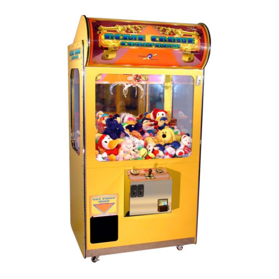
Congratulations! You are now operating the most innovative, reliable, and revenue-generating crane available. Here are some of the highlights of this patented machine: • “Never Empty” illusion created by self-adjusting floor height • Holds more merchandise than much-larger cranes • “Ultimate Tease” air claw lets players feel they almost won every time •... -
Page 5: Game Setup
Game Set Up Note: X-treme model cranes are shipped with Marquee and Control Panel installed. When the game must pass through a narrow door or opening, it may be necessary to remove the Marquee and the Control Panel. If it is necessary to remove the Control Panel, disconnect the Control Panel harness from the main harness, remove the 8 screws securing the control panel in the front door, and remove control panel. - Page 6 • Roll the marquee plastic2 back over the top of the Form Blocks5 and insert attaching studs and nuts through the keyholes6 located in the top of the game, capturing artwork behind t he marquee plastic2. • Tighten nuts in keyholes6. 3.
- Page 7 5. Free Crane Mechanism • Cut cable tie used to s ecure crane mechanism during shipping • Verify crane mechanism is free to move by sliding from side to side and from front to back with your hand 6. Install coin in comparator (skip this step if using a no comparator style coin mech) •...
-
Page 8: Adjustments And Settings
the merchandise side to keep the containment plate from falling over. • Load the game w ith merchandise. djust game volume, claw pressure, and programmable options as necessary. See Game Adjustments section. ote: Do not remove the casters. The game requires the additional height in order to properly operate with full playfield floor travel. -
Page 9: Playfield Floor Height Adjustment
Playfield Floor Height Adjustment The playfield floor automatically adju sts as product is won. If you are not using this feature, the floor can be manually adjusted. • Press the SW1 button1 on the power distribution pcb2 in order to lower the floor. -
Page 10: Programming Options
Attract Movement The claw moves fro m the home position over the playfield, drops into the merchandise, raises, and returns home (simulated game play) approximately every 5 minutes when enabled. Disabled Dip 7 Enabled Auto Playfield Floor Adjustment The crane automatically adjusts the floor height to maintain full look when enabled. -
Page 11: Repair And Maintenance
4. Press the Drop Claw button5 to enter the new value. The 2 digit credit display3 will show , or OK. 5. Bump the joystick4 up or down in order to scroll to another option that you would like to adjust, or go to option 10 (credit display will flash , or EXIT) and press the Drop Claw button5 to exit and save changes. -
Page 12: Clean Drop Return Claw Opto
2. Remove (2) marquee fastening nuts1 located on the inside, upper part of the crane behind the marquee. Pull the marqu ee forward and up releasing the marquee from the keyway slots 2 in the top of the cabinet. Change the b ulb(s) and replace marquee. -
Page 13: Replace Crane Mechanism
5. Reinstall crane mechanism with front Mech Mount Bracket3 located between the Front Rollers4. Replace Side Glass (Extreme Model) 1. Disconnect AC power from machine 2. Disconnect wire harness to the crane mechanism 3. Disconnect wire harness to the crane mechanism side to X-axis Motor Assembly1 (if replacing right side glass) 4. -
Page 14: Replace Prize Sensor
5. Remove (3) screws from each hole cover2 and swivel hole covers so that the prize floor holes3 are exposed. 6. Lift prize floor4 out of game using prize floor holes3 as handles. 7. Remove prize chute5 by removing _ screws attaching the chute to the left side and the back panels. -
Page 15: Replace Floor Lift Sensors
3. Remove mounting screws securing Floor Lift Sensors2. 4. Replace sensors, and reconnect harness. Replace Power Supply 1. Disconnect AC power from the machine. 2. Disconnect harness to power supply. 3. Remove (2) nuts attaching power supply to cabinet side and (3) screws that attach power supply to game bottom. -
Page 16: Claw Has Little Power
o Check to be sure that the sensor tab1 interrupts the opto. When the claw is pushed up toward the top of the cabinet, a LED2 on the opto sensor board3 should light up. If it does not, either the sensor tab1 is out of adjustment or the opto sensor board3 is bad. -
Page 17: Elevator Exceeds Upper Limit
• The LED1 on the sensor board2 should be on until the elevator lift rod3 raises to its upper limit. The sensor LED1 should then turn off when the elevator lift rod3 lifts up beyond the sensor. The output of the sensor board2 should then transition high (+5V). If the LED indicators do not illuminate, or the output does not transition high when the elevator rod lifts beyond the sensor, check the power and connections to the sensor boards. -
Page 18: Schematics
Schematics ac power 115 volt / 220 volt POWER INPUT BOX ON/OFF SWITCH 5 AMP. FUSE BLACK COMPUTER 115/ 230 ac WHITE POWER CORD 50/60 hz 5 AMP. FUSE GREEN/YELLOW 16 GA. EARTH GROUND CONNECTSTO ALL BONDED METAL PARTS POWER SUPPLY PCB Power Distribution Output... - Page 19 Crane Mechanism PCB Z Axis Z Axis Motor Stepper Drive Green/Orange Black Pin 1 Pin 2 Brown Green Pin 2 Pin 9 Yellow/Black Pink Pin 3 Pin 1 White/Green Blue Pin 4 Pin 8 J101 Black Yellow/White/Violet Pin 7 Black/Pink Green Pin 8 Orange/Black...
- Page 20 Control Panel Power Distribution PCB Output Yellow 12VB Black Black Coin J201 Mech 1 White Orange/White Pin 3 Coin Black Mech 2 White Power Distribution PCB Output Yellow 12VB Black White/Brown Dollar Black Bill J201 Validator White/Brown Pin 4 Black (18G) AC Outlet White (18G) at switch box...
- Page 21 Power Distribution Claw Rotate Control PCB Output Yellow/Green/Red Right 12VB Yellow Gear Motor Green/White Black Left PWR Supply Blue -12V Floor Lift Down Limit J201 Power Distribution White/Black Pin 7 PCB Output Black PCB Air Pump PCB Air Pump Air Pump Power Distribution PCB Output Black...
- Page 22 PCB Floor Lift Stepper Drive White/Blue/Orange Black Pin 2 Yellow/Orange Green Pin 9 Floor Lift White/Violet Pink Motor Pin 1 Grey/White Blue Pin 8 J101 Green Yellow/White/Violet Pin 7 Black/Pink Blue Pin 8 Orange/Black Yellow Pin 9 X Axis White/Black/Red Pink Motor Pin 10...
Need help?
Do you have a question about the Acme Crane Company and is the answer not in the manual?
Questions and answers