Advertisement
Available languages
Available languages
Air-Conditioners For Building Application
INDOOR UNIT
Bina Uygulaması için Klimalar
İÇ ÜNİTE
PLFY-M·VEM Series
INSTALLATION MANUAL
For safe and correct use, read this manual and the outdoor unit installation manual thoroughly before installing
the air-conditioner unit.
MONTAJ ELKİTABI
Emniyetli ve doğru kullanım için, klima cihazını monte etmeden önce bu kılavuzu ve dış ünite montaj kılavuzunu
tamamıyla okuyun.
For use with the R32/R410A
R32/R410A ile beraber kullanmak için
FOR INSTALLER
MONTÖR İÇİN
English
Türkçe
Advertisement
Table of Contents

Related Manuals for Mitsubishi Electric CITY MULTI PLFY-M-VEM Series


Summary of Contents for Mitsubishi Electric CITY MULTI PLFY-M-VEM Series
-
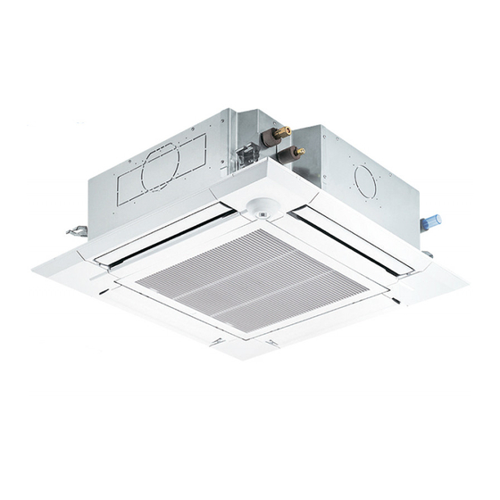
Page 1: Indoor Unit
Air-Conditioners For Building Application INDOOR UNIT Bina Uygulaması için Klimalar İÇ ÜNİTE PLFY-M·VEM Series For use with the R32/R410A R32/R410A ile beraber kullanmak için INSTALLATION MANUAL FOR INSTALLER English For safe and correct use, read this manual and the outdoor unit installation manual thoroughly before installing the air-conditioner unit. - Page 2 Manual Download http://www.mitsubishielectric.com/ldg/ibim/ en Go to the above website to download manuals, select model name, then choose language. de Besuchen Sie die oben stehende Website, um Anleitungen herunterzuladen, wählen Sie den Modellnamen und dann die Sprache aus. Rendez-vous sur le site Web ci-dessus pour télécharger les manuels, sélectionnez le nom de modèle puis choisissez la langue. Ga naar de bovenstaande website om handleidingen te downloaden, de modelnaam te selecteren en vervolgens de taal te kiezen.
-
Page 3: Table Of Contents
Contents 5. Electrical work ...................7 1. Safety precautions ..................1 6. Test run ....................12 2. Installation location ..................2 7. Installing the grille ..................14 3. Installing the indoor unit ................2 4. Refrigerant pipe and drain pipe ..............5 Note: The phrase “Wired remote controller” in this installation manual refers only to the PAR-40MAA. If you need any information for the other remote controller, please refer to either the installation manual or initial setting manual which are included in these boxes. 1. Safety precautions ► Before installing the unit, make sure you read all the “Safety precautions”. -
Page 4: Installation Location
1. Safety precautions 1.1. Before installation (Environment) Caution: • Do not use the unit in an unusual environment. If the air conditioner is • When the room humidity exceeds 80% or when the drainpipe is clogged, installed in areas exposed to steam, volatile oil (including machine oil), or water may drip from the indoor unit. Do not install the indoor unit where sulfuric gas, areas exposed to high salt content such as the seaside, the such dripping can cause damage. - Page 5 3. Installing the indoor unit 3.2. Ceiling openings and suspension bolt installation 950 D locations (Fig. 3-2) 20 – 45 20 – 45 860 – 910 C 795 B Warning: • This unit should be installed in rooms which exceed the floor space specified in outdoor unit installation manual. Refer to outdoor unit installation manual. • Install the indoor unit at least 2.5 m above floor or grade level. For appliances not accessible to the general public. • Refrigerant pipes connection shall be accessible for maintenance purposes. • Using the installation template (top of the package) and the gauge (supplied as an accessory with the grille), make an opening in the ceiling so that the main unit can be installed as shown in the diagram.
- Page 6 3. Installing the indoor unit 3.4. Suspension structure (Give site of suspension strong structure) (Fig. 3-4) A Main unit • The ceiling work differs according to the construction of the building. Building B Grille constructors and interior decorators should be consulted for details. C Pillar (1) Extent of ceiling removal: The ceiling must be kept completely horizontal and the ceiling foundation (framework: wooden slats and slat holders) must be reinforced in order to protect the ceiling from vibration.
-
Page 7: Refrigerant Pipe And Drain Pipe
4. Refrigerant pipe and drain pipe 4.1. Refrigerant and drainage piping locations of indoor unit (Fig. 4-1) The figure marked with * in the drawing represent the dimensions of the main unit excluding those of the optional multi function casement. A Drain pipe B Ceiling C Grille D Refrigerant pipe (liquid) E Refrigerant pipe (gas) (mm) F Main unit Models... - Page 8 4. Refrigerant pipe and drain pipe 4.4. Indoor unit (Fig. 4-3) Heat insulation for refrigerant pipes: A Refrigerant pipe and heat insulation 1 Wrap the enclosed large-sized pipe cover around the gas pipe, making sure that B Pipe cover (large) the end of the pipe cover touches the side of the unit. C Pipe cover (small) 2 Wrap the enclosed small-sized pipe cover around the liquid pipe, making sure D Refrigerant pipe (gas)
-
Page 9: Electrical Work
5. Electrical work 5.1. Indoor unit (Fig. 5-1) 1. Loosen the two screws securing the electrical wiring service panel, and then turn the electrical wiring service panel. [Fig. 5-1 1] 2. Loosen the one screw securing the electrical wiring service panel at the cable entry (remote controller cable and indoor-outdoor connection cable), and then turn the service panel to the position shown in the diagram. - Page 10 5. Electrical work • Connecting two wires on one side is prohib- <When wiring two indoor-outdoor connection cables> ited. • Connecting three wires or more to the same • If the cables have the same diameter, insert them into the terminal is prohibited. cut outs on both sides.
- Page 11 5. Electrical work 5.3. Types of control cables 1. Wiring transmission cables 3. MA Remote control cables Types of transmission cable Shielding wire CVVS or CPEVS Types of remote control cable 2-core cable (unshielded) Cable diameter More than 1.25 mm² Cable diameter 0.3 to 1.25 mm² Length Less than 200 m Length Less than 200 m 2. M-NET Remote control cables Types of remote control cable Shielding wire MVVS...
- Page 12 5. Electrical work 5.6. Switch setting for high ceiling or at the time of changing the number of air outlets (Fig. 5-6) With this unit, the air flow rate and fan speed can be adjusted by setting the SW21 Note: Make sure the SW21 switch are set, otherwise problems such as not getting (slide switch). Select a suitable setting from the table below according to the instal- cool/warm may occur. lation location. PLFY-M20VEM PLFY-M50VEM PLFY-M25VEM...
- Page 13 5. Electrical work 5.9. Initial setting The following settings can be made in the initial setting mode. Item Setting Fig. 5-8 Temperature unit ºC/ºF Time display 12-hour format/24-hour format AUTO mode Single set point/Dual set point Pair No. 0–3 Backlight On/Off 5.9.1. Switching to the initial setting mode 1.
-
Page 14: Test Run
6. Test run 6.1. Before test run ► After completing installation and the wiring and piping of the indoor and ► Do not carry out this test on the control wiring (low voltage circuit) terminals. outdoor units, check for refrigerant leakage, looseness in the power supply Warning: or control wiring, wrong polarity, and no disconnection of 1 phase in the Do not use the air conditioner if the insulation resistance is less than 1.0 MΩ. supply. ► Use a 500-volt megohmmeter to check that the resistance between the power supply terminals and ground is at least 1.0 MΩ. 6.2. Test run Controller interface The following 3 methods are available. 6.2.1. Using wired remote controller (Fig. 6-1) ▌1 [ON/OFF] button Press to turn ON/OFF the indoor unit. ▌2 [SELECT] button Press to save the setting. ▌3 [RETURN] button Press to return to the previous screen. - Page 15 6. Test run Step 1 Switch the remote controller to “Test run”. 1 Select “Service” from the Main menu, and press the button. 2 When the Service menu is selected, a window will appear asking for the password. (Fig. 6-2) To enter the current maintenance password (4 numerical digits), move the cursor to the digit you want to change with the button, and set each number (0 through 9) with the button.
-
Page 16: Installing The Grille
7. Installing the grille 7.1. Checking the contents (Fig. 7-1) • This kit contains this manual and the following parts. Accessory name Q’ty Remarks 1 Grille 950 × 950 (mm) 2 Installation gauge (Divided into 4 parts) 3 Screw (4 × 16) For PLP-6EAE, PLP-6EALE, PLP-6EALME 4 i-see Sensor corner panel For PLP-6EAE, PLP-6EALE, PLP-6EALME 5 Wireless remote controller... - Page 17 7. Installing the grille 7.4.2. Temporary installation of the grille (Fig. 7-6) A Main unit • Join the corner of drain pipe on the main unit with the corner with hole on the grille B Corner of drain pipe and put them together temporarily by hanging the hook of the grille to the claw of C Claw on the main unit the main unit.
- Page 18 7. Installing the grille 7.5. Installing the intake grille (Fig. 7-12) Note: When reinstalling the corner panels (each with a safety strap attached), con- nect the other end of each safety strap to the grille as shown in the illustration. * If the corner panels are not attached surely, they may fall off while the main unit is operating. • Perform the procedure that is described in “7.2. Preparing to attach the grille” in reverse order to install the intake grille and the corner panel.
- Page 19 İçindekiler 1. Güvenlik Önlemleri ..................1 5. Elektrik işleri ....................7 2. Montaj yeri ....................2 6. Çalışma testi ....................12 3. İç ünitenin montajı ..................2 7. Izgaranın takılması ..................14 4. Soğutucu borusu ve drenaj borusu ............5 Not: Bu kurulum kılavuzundaki “Kablolu uzaktan kumanda” terimi PAR-40MAA anlamına gelmektedir. Diğer uzaktan kumanda ile ilgili bilgi için lütfen bu kutuların içindeki kurulum kılavuzuna veya başlangıç ayarı kılavuzuna başvurun. 1. Güvenlik Önlemleri ► Üniteyi monte etmeden önce “Güvenlik Önlemleri” nin hepsini okumalısınız. ► Bu cihazı güç sistemine bağlamadan önce, güç sağlayıcı kurum ile görüşün ya da onayını alın.
- Page 20 1. Güvenlik Önlemleri 1.1. Montajdan önce (Ortam) Dikkat: • Odadaki nem oranı %80’i aştığında veya drenaj borusu tıkandığında, iç ünite • Cihazı alışılmadık ortamlarda kullanmayın. Klima cihazı buhar, uçucu yağ su damlatabilir. İç üniteyi, su damlamasından zarar görebilecek yerlere monte (makine yağı dahil) ve sülfürik gazın bulunduğu ya da deniz kenarı gibi yük- etmeyin. sek tuz oranına maruz kalan yerlerde kurulursa, performansı önemli ölçüde • Cihazı hastane veya iletişim ofislerine monte ederken, gürültü ve elektronik düşebilir ve iç aksamı zarar görebilir. parazite karşı hazırlıklı olun. Akım dönüfltürücüler, ev aletleri, yüksek fre- • Cihazı yanıcı gazların oluşabileceği, sızabileceği, akabileceği veya birike- kanslı tıbbi cihazlar ve radyo iletişim cihazları, klima cihazının çalışmasının bileceği yerlere monte etmeyin. Cihazın yakınında yanıcı gazların birikmesi aksamasına veya bozulmasına yol açabilir. Aynı zamanda klima cihazı da...
- Page 21 3. İç ünitenin montajı 3.2. Tavandaki açıklıklar ve askı cıvatalarının yerleri 950 D (Fig. 3-2) 20 – 45 20 – 45 860 – 910 C 795 B Uyarı: • Bu ünite dış ünitenin montaj kılavuzunda belirtilen zemin alanından daha geniş odalara monte edilmelidir. Dış ünite montaj kılavuzuna bakın. • İç üniteyi tabandan veya zemin seviyesinden en az 2,5 m yükseğe monte edin. Bu cihazlar kamu tarafından erişilebilir değildir. • Soğutucu madde borularının bağlantıları bakım amacıyla erişilebilir olmalıdır. • (Ambalajın üstündeki) montaj şablonunu ve (ızgarayla birlikte aksesuar olarak sağlanan) geyci kullanarak, ana ünite aşağıdaki flemada gösterilen biçimde monte edilecek şekilde, tavanda bir delik açın.
- Page 22 3. İç ünitenin montajı 3.4. Asma düzeninin yapısı (asılacağı yerin yapısını güçlendiriniz) (Fig. 3-4) • Tavanda yapılacak işler, binanın yapısına göre değişir. Bunun ayrıntıları için inşa- A Ana ünite B Izgara atçılara ve iç mimarlara danışılmalıdır. C Dikme (1) Tavanın ne ölçüde açılacağı: Tavan tamamen yatay durumda kalmalı ve tavanı sarsıntının etkilerinden korumak için tavan karkasını...
- Page 23 4. Soğutucu borusu ve drenaj borusu 4.1. İç ünitedeki soğutucu ve drenaj borularının konumları (Fig. 4-1) Resimde * işaretli rakamlar, ana ünitenin seçmeli çok işlevli kasa dışındaki boyutlarını temsil etmektedir. A Drenaj borusu B Tavan C Izgara D Soğutucu borusu (sıvı) E Soğutucu borusu (gaz) (mm) F Ana ünite Modeller Seçmeli çok işlevli kasa monte edildiğinde, resimde belirtilen boyutlara 135 mm 20, 25, 32, 40, 50 76,5 ekleyin.
- Page 24 4. Soğutucu borusu ve drenaj borusu 4.4. İç Ünite (Fig. 4-3) Soğutucu boruları için ısı izolasyonu: A Soğutucu borusu ve izolasyon 1 Birlikte verilen büyük boy boru kılıfını, kılıfın ucunun ünitenin yanına dayanmasına maddesi B Boru kapağı (büyük) dikkat ederek gaz borusunun etrafına sarın. C Boru kapağı (küçük) 2 Birlikte verilen küçük boy boru kılıfını, kılıfın ucunun ünitenin yanına dayanmasına D Soğutucu borusu (gaz) dikkat ederek sıvı...
- Page 25 5. Elektrik işleri 5.1. İç ünite (Fig. 5-1) 1. Elektrik kablosu servis panelini sabitleyen iki vidayı sökün ve ardından elektrik kablosu servis panelini çevirin. [Fig. 5-1 1] 2. Kablo girişindeki (uzaktan kumanda kablosu ve iç-dış bağlantı kablosu) elektrik kablolama servis panelini sabitleyen tek vidayı gevşetin, ardından servis panelini şekilde gösterilen konuma döndürün.
- Page 26 5. Elektrik işleri <İki iç-dış ünite kablosu birbirine bağlandığında> • İki kabloyu aynı tarafa yerleştirmek yasaktır. • Aynı terminale üç veya daha fazla kablo • Kabloların aynı çapa sahip olması halinde onları her iki bağlamak yasaktır. tarafta bulunan kesiklere yerleştirin. • Farklı çaplara sahip kabloları bağlamak UYARI •...
- Page 27 5. Elektrik işleri 5.3. Kontrol kablosu türleri 1. İletim kablosu tesisatı 3. MA Uzaktan kumanda ünitesi kabloları İletim kablosu türleri CVVS ya da CPEVS blendaj kablosu Uzaktan kumanda 2-hatlı kablo (yalıtımsız) ünitesi kablosu türü Kablo çapı 1,25 mm ’den fazla Kablo çapı 0,3 - 1,25 mm Uzunluk 200 m’den kısa Uzunluk 200 m’den kısa 2. M-NET Uzaktan kumanda ünitesi kabloları...
- Page 28 5. Elektrik işleri 5.6. Yüksek tavan için veya hava çıkışlarının sayısının değiştirilmesi sırasında anahtar düzenlemeleri (Fig. 5-6) Bu ünitede hava akış değeri ve fan hızı, SW21 (sürgülü anahtar) ile ayarlanabilir. Not: SW21 anahtarının ayarlandığından emin olun, aksi takdirde sıcak/soğuk ala- Aşağıdaki tablodan montajın yapılığı yere göre uygun düzenlemeyi seçin. mama gibi problemler oluşabilir. PLFY-M20VEM PLFY-M50VEM PLFY-M25VEM PLFY-M63VEM PLFY-M100VEM PLFY-M32VEM PLFY-M80VEM...
- Page 29 5. Elektrik işleri 5.9. Başlangıç ayarı Aşağıdaki ayarlar başlangıç ayar modunda yapılabilir. Öğe Ayar Fig. 5-8 Sıcaklık birimi ºC/ºF Zamanlayıcı ekranı 12 saat biçimi/24 saat biçimi AUTO (OTOMATİK) mod Tek ayar noktası/Çift ayar noktası Çift No. Arka aydınlatma Açma/Kapatma 5.9.1. Başlangıç ayar moduna geçilmesi 1. Klimayı durdurmak için düğmesine 1 basın.
- Page 30 6. Çalışma testi 6.1. İşletme testinden önce ► İç ve dış ünitenin montajının ve kablo ve boru bağlantılarının tamamlanma- ► Bu testi kontrol kablosu (düşük gerilim devresi) terminallerinde yapmayınız. sından sonra, soğutucu kaçağı, elektrik ve kontrol kablolarında gevşeme, Uyarı: hatalı polarite ve fazlardan birinde kopma olup olmadığına bakınız. İzolasyon direnci 1,0 MΩ’dan azsa klimayı kullanmayınız. ► 500-Voltluk bir megommetreyle besleme kaynağı terminalleriyle toprak arasında en az 1,0 MΩ direnç bulunduğunu kontrol ediniz. 6.2. Çalışma testi Kumanda arayüzü Şu 3 yöntem kullanılabilir. 6.2.1. Kablolu uzaktan kumanda kullanarak (Fig. 6-1) ▌1 [AÇMA/KAPATMA] düğmesi İç üniteyi AÇMAK/KAPATMAK için basın. ▌2 [SEÇİM] düğmesi Ayarı kaydetmek için basın. ▌3 [GERİ DÖN] düğmesi Önceki ekrana dönmek için basın.
- Page 31 6. Çalışma testi Adım 1 Uzaktan kumandayı “Test run” (Test çalıştırma) moduna alın. 1 Ana menüden “Service” (Servis) öğesini seçin ve düğmesine basın. 2 Servis menüsü seçildiğinde, bir pencere açılarak parola isteyecektir. (Fig. 6-2) Mevcut bakım parolasını (4 rakam) girmek için, veya düğmesi ile imleci değiştirmek istediğiniz haneye getirin ve her sayıyı (0’dan 9’a kadar) veya düğ- düğmesine basın.
- Page 32 7. Izgaranın takılması 7.1. İçindekilerin kontrolü (Fig. 7-1) • Bu kit, bu elkitabını ve aşağıdaki parçaları içerir. Aksesuarın adı Miktar Açıklama Izgara 950 × 950 (mm) Geyç (dört bölmeli) PLP-6EAE, PLP-6EALE, PLP- Vida (4 × 16) 6EALME için PLP-6EAE, PLP-6EALE, PLP- i-see sensor köşe paneli 6EALME için Kablosuz uzaktan kumanda PLP-6EALM, PLP-6EALME için...
- Page 33 7. Izgaranın takılması 7.4.2. Izgaranın geçici olarak montajı (Fig. 7-6) A Ana ünite • Ana ünitenin drenaj borusu köşesini ızgaradaki delikle denk gelecek şekilde yerleş- B Drenaj borusu köşesi tirin ve ızgaranın kancasını ana ünitede bulunan mandala asarak geçici bir şekilde C Ana ünitedeki mandal birleştirin. D Izgara 1 E Izgaradaki delik 7.4.3. Izgaranın sabitlenmesi F Geçici montaj için kanca...
- Page 34 7. Izgaranın takılması 7.5. Giriş ızgarasının takılması (Fig. 7-12) Not: Köşe panellerini (her birine emniyet teli takılmış olarak) tekrar yerlerine takar- ken, her emniyet telinin diğer ucunu resimde görüldüğü gibi ızgaraya bağlayın. * Eğer köşe panelleri sağlam tutturulmazsa, ünitenin çalışması sırasında düşebilirler. • Giriş ızgarasını ve köşe panelini monte etmek için “7.2. Izgarayı takma hazırlığı” bölümünde anlatılan prosedürü tersten izleyin. • Giriş ızgarasının yönü müşterinin arzusuna uygun olarak değiştirilebilir. A Vida (4 ×...
- Page 36 This product is designed and intended for use in the residential, commercial and light-industrial environment. Please be sure to put the contact address/telephone number on this manual before handing it to the customer. HEAD OFFICE: TOKYO BUILDING, 2-7-3, MARUNOUCHI, CHIYODA-KU, TOKYO 100-8310, JAPAN RG79F456H01 Printed in UNITED KINGDOM...