
Related Manuals for McConnel ROBOCUT RC28


Summary of Contents for McConnel ROBOCUT RC28
- Page 1 McCONNEL Publication 936 May 2019 Part No. 24214.36 Revision: ROBOCUT Model RC28 REMOTE CONTROLLED COMPACT MOWER Operator Manual...
- Page 2 VERIFICATION OF WARRANTY REGISTRATION DEALER WARRANTY INFORMATION & REGISTRATION VERIFICATION It is imperative that the selling dealer registers this machine with McConnel Limited before delivery to the end user – failure to do so may affect the validity of the machine warranty.
-
Page 4: Warranty Policy
1500 hours. Engine warranty will be specific to the Manufacturer of that unit. 1.02. All spare parts supplied by McConnel Ltd and purchased by the end user are warranted to be free from defects in material and workmanship from the date of sale to the original purchaser for a period of 6 months. - Page 5 2.02. Any fault must be reported to an authorised McConnel Ltd dealer as soon as it occurs. Continued use of a machine, after a fault has occurred, can result in further component failure for which McConnel Ltd cannot be held liable.
- Page 6 MISCELLANEOUS 4.01. McConnel Ltd may waive compliance with any of the terms of this limited warranty, but no waiver of any terms shall be deemed to be a waiver of any other term. 4.02. If any provision of this limited warranty shall violate any applicable law and is held to be unenforceable, then the invalidity of such provision shall not invalidate any other provisions herein.
-
Page 7: Declaration Of Conformity
DECLARATION OF CONFORMITY Conforming to EU Machinery Directive 2006/42/EC McCONNEL LIMITED, Temeside Works, Ludlow, Shropshire SY8 1JL, UK Hereby declare that: The Product; Radio Controlled Tracked Mower Product Code; RMOW Serial No. & Date ………………………………… Type …………………………... - Page 8 Shropshire England Telephone: +44 (0)1584 873131 www.mcconnel.com In line with our policy of constant improvement, this publication will be periodically updated; to ensure you have access to the latest version of this manual please visit the manuals library on our website where an ‘up-to-date’ version can be referenced online, or downloaded.
-
Page 9: Table Of Contents
CONTENTS General Information ......................1 Machine Description ......................2 Machine Identification ......................2 Features & Specifications ....................3 Technical Specifications ...................... 4 Safety Information ........................ 5 Machine Delivery ......................... 8 Machine Overview ....................... 9 Engine Compartment ......................9 Emergency Stop Buttons (E-Stop) ..................10 Safety Devices &... - Page 10 Operation ........................... 22 Recommended Safety Gear ..................22 Work Lighting Conditions ....................22 Track Protection ......................22 Brakes ..........................24 Emergency Towing ....................... 24 Parking The Machine ....................24 Fuel ............................ 25 Emergency Control Unit (Get Me Home) ................26 Manual Controller ......................
-
Page 11: General Information
GENERAL INFORMATION Read this manual before fitting or operating the machine or accessory. Whenever any doubt exists contact your local dealer or the McConnel Service Department for assistance. Only use ‘Genuine McConnel Parts’ on McConnel machinery and equipment. DEFINITIONS The following definitions apply throughout this manual;... -
Page 12: Machine Description
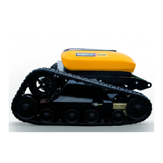
MACHINE DESCRIPTION The McConnel Robocut RC28 is a compact, all-terrain, remote controlled mower with bi- directional cutting capability for high performance efficient mowing/mulching of grass and herbaceous vegetation. Machines feature a powerful Vanguard 28HP petrol engine with low fuel consumption and low emissions which, when combined with its hybrid electric drive, delivers smooth operation on all types of terrain including slopes of up to 55°. -
Page 13: Features & Specifications
FEATURES & SPECIFICATIONS ROBOCUT RC28 28HP 28HP (21kW) Vanguard Petrol Engine ○ Fully enclosed body panels ○ Tracked carriage ○ Electric motor driven tracks ○ Ability to operate on slopes up to 55° ○ Remote controlled cutting height adjustment (25mm to 175mm) ○... -
Page 14: Technical Specifications
TECHNICAL SPECIFICATIONS ROBOCUT RC28 28HP Engine Air-cooled, 2 cylinder, 4-stroke, OHV engine Power 28HP / 21kW Fuel type Petrol Track power Electric motors Travel speed 10kph / 6.2mph Brakes Short-circuit brake system Ground pressure 2800 kg/m² (6173 lbs/m²) Rotor No. -
Page 15: Safety Information
SAFETY INFORMATION This machine has the potential to be extremely dangerous - in the wrong hands it can kill or maim; It is therefore imperative that both owner and operator of the machine reads the following section to ensure they are fully aware of the dangers that do, or may exist, and fully understand their responsibilities surrounding use and operation of this machinery. - Page 16 Never operate the machine when standing directly in the line of travel. Do not use the machine on sand piles, gravel, or other similar loose materials. Only operate the machine in good light conditions. Never start or run the machine in an enclosed area or building. Keep the machine clean to avoid build ups of dry materials that could ignite on hot components.
- Page 17 No advice given here can replace ‘good common sense’ and ‘total awareness’ at all times, but it will go a long way towards the safe use of your McConnel machine. Operating, servicing and maintaining this equipment can...
-
Page 18: Machine Delivery
MACHINE DELIVERY Robocut RC28 machines are delivered ready for use pre-filled with all the necessary lubricants and fluids other than fuel. Before use, all delivery packaging should be removed and the machine fully inspected; if there are any signs of damage or missing components it must be reported to your supplier/dealer immediately. -
Page 19: Machine Overview
MACHINE OVERVIEW Engine Compartment: Antenna Emergency Stop Fuel Tanks Fuse Box Drive Wheels Electrics Deck Actuator Rubber Track Idler Wheels Track Tensioner Undercarriage Track Rollers ENGINE COMPARTMENT Component Identification E-Stop Antenna PCB Controller Receiver Air Filter Feeder Fuel Tank Primary Fuel Tank Engine Oil Reservoir... -
Page 20: Emergency Stop Buttons (E-Stop)
EMERGENCY STOP BUTTONS (E-STOP) Location of Emergency Stop Buttons E-Stop buttons are located on top of the machine at the rear of the engine compartment and on the remote control unit. The E-Stop button on the machine also acts as the main power ON/OFF button for the machine;... -
Page 21: Safety Devices & Emergency Stop (E-Stop)
Do not approach the machine if it is moving. 3) Press machine’s E-Stop button. 4) Turn control unit power switch to the OFF position (anti-clockwise) and remove the key. Contact your Authorised Dealer or McConnel Service; do not attempt to operate the machine until advice has been sought. -
Page 22: Remote Control Unit
REMOTE CONTROL UNIT Operators must wear personal safety gear at all times whilst operating the machine and stand in a safe operating position with a clear view of the machinery and the work area. Controls Identification Steering EMERGENCY STOP Track Bias Speed Engine Speed... -
Page 23: Lcd Display
Control Unit – Function Operation LCD Display Reports the following information; Screen #1 Track Speed (kph) Engine Speed (rpm) Job minutes records the current operating Cutting Height (mm) period only; if the control unit is switched off Job minutes the job minutes reading will return to zero. Press OPT button to ‘toggle’... -
Page 24: Steering Bias Dial
Steering Bias Dial Control for setting steering angle bias when operating on sloped ground. Left Steering Bias: Turn control dial to the left to select desired LH bias. No Steering Bias: Place control dial into the central position. Right Steering Bias: Turn control dial to the right to select desired RH bias. Track Speed (Governor) Sets maximum top speed limit. -
Page 25: Starting & Stopping The Engine
STARTING & STOPPING THE ENGINE Before attempting to start the engine ensure you have read and understood the manual and observed all safety instructions surrounding use of the engine and the machine. Engine must only be started in open air, never in an enclosed environment. -
Page 26: Emergency Stopping (E-Stop)
Emergency Stopping (E-Stop) In emergency situations, the engine and all machine functions can be immediately stopped by pressing an E-Stop button. E-Stop buttons are located on the remote control unit and on the top of the machine to the rear of the engine compartment. When an E-Stop button is pressed (activated), all machine movements and functions will cease immediately and the engine will be automatically switched off. -
Page 27: Driving & Manouevering
DRIVING & MANOUEVERING Operation of the machine must only be performed by a responsible person who has read the manual and is familiar with the machine’s controls and all aspects relating to the safe use of this equipment. e that all new operators practice using the machine, without the rotors running, It is advisabl in a safe open area to familiarise themselves with the controls and movements of the machine. -
Page 28: Steering Bias
Steering Bias The steering bias feature allows the operator to set a ‘degree of steer’ for manoeuvring the machine across slopes, setting and adjustment is performed using the steering bias dial; Turn control dial to the left to select a desired degree of left steering bias. Turn control dial to the right to select a desired degree of right steering bias. -
Page 29: Cutting Deck
CUTTING DECK Cutting Height The machine can be set to cut at any height between 25mm and 175mm. The cutting height selected should be one that offers the desired finish. If the material being cut is particularly tall or thick or causes the machine to ‘labour’ whilst working, it is advisable to begin cutting at a high setting and progressively reduce the height until the required finish is achieved. -
Page 30: Operating Position & Distance
OPERATING POSITION & DISTANCE Only operate the machine from a safe distance and position that provides an unobstructed view of the machine and work area. When operating this machinery you are responsible for your own safety and the safety of all others who enter the work area. 20°... -
Page 31: Work Area Precautions
WORK AREA PRECAUTIONS Work and Work Area Precautions The following checks should be made prior to operation in the work area; Inspect the work area prior to operations; check for and remove foreign bodies such as large stones, metal items, wire, glass etc. which could damage the machinery or be may be ejected by the equipment being used. -
Page 32: Operation
OPERATION Personal Protection Equipment (PPE) Operators must wear suitable safety gear when operating and/or maintaining this machine. Recommended Safety Gear Safety Gloves Safety Boots Eye Protection Protective Overalls Safety Helmet Ear Defenders Dust Mask ... - Page 33 Do not change direction whilst moving on kerbs, rocks or surfaces with considerable differences in height (more than 20cm); in these instances always move perpendicular to the obstacles. When reversing uphill, do not steer when transferring from the level surface to the slope;...
-
Page 34: Brakes
BRAKES Machine movement is controlled by electric track motors which drive the machine when they receive electrical power from the generator, motion is stopped by ‘short-circuiting’ the motors which generates a braking effect to halt the machine. If the engine is switched off, or cuts-out for any reason, the motors ‘lock-out’ to hold the machine;... -
Page 35: Fuel
FUEL Fuel Type: standard unleaded motor vehicle petrol. Fuel Capacity: 20 litres (2x10 litre removable fuel tanks). Only fuel the machine on a level well-ventilated site away from sources of sparks, flames or heat. Machine power must be SHUT-OFF (machine E-Stop activated). Refuelling must only be performed with engine switched off and in a cooled down condition. -
Page 36: Emergency Control Unit (Get Me Home)
EMERGENCY CONTROL UNIT (GET ME HOME) Manual Control Unit (Emergency Track Operation only) A manual control device for track operation is provided with the machine to allow the operator to bypass the radio controller in the event of a controller malfunction. When connected to the machine this devise will allow the operator to start the engine, raise and lower the deck, and manoeuvre the mower in any direction. -
Page 37: Manual Controls Operation
Manual Controls Operation (refer to control illustration above) Starting the engine; Set E-Stop button in the de-activated position. Press rocker button at point ‘1’ to switch ignition ON. Press button ‘2’ to start engine, release button as soon as engine starts. Stopping the engine;... -
Page 38: Maintenance
A purpose-made maintenance stand is available for the RC28 that allows safe and easy access to the base of the machine for service and maintenance duties. Contact McConnel for further details. ENGINE OIL Oil Capacity & Type 6.0 litres (10.56 pints) 5w40 engine oil. -
Page 39: Air Filter
AIR FILTER Air Filters Tools required; no tools are needed to access filter cartridges. Air filters should be checked daily and cleaned on a regular basis. Filter cartridges must be replaced at the specified time periods stated in the service schedule. Filter Cartridge Removal The machine uses 2 filters cartridges, a primary filter and a secondary filter;... -
Page 40: Rotors & Blades
ROTORS & BLADES The machine has two belt-driven rotors equipped with sets of opposing blades mounted on a blade carrier; blade sets comprises of an updraft blade and a top cut blade. The ‘fast-stop’ rotors, which are driven by the engine via an electromagnetic clutch, are mounted on the machine in a staggered configuration to provide overlapped cutting. -
Page 41: Belts
BELTS Access to Belts Access to the belts for checking and/or tensioning is from beneath the machine and requires removal of the cover plate; the plate is secured with 7 bolts. Tools required; 10mm spanner or socket. Belts & Pulley’s - Identification A. -
Page 42: Rotor Belt - Tension Adjustment
Rotor Belt – Tension Adjustment Tools required; 10mm & 12mm spanner. Slacken off both nuts (A). Rotate nut (B) to adjust belt tension. Re-tighten nuts (A) when tension is correct. Re-check belt to confirm tension is correct. Generator Belt –... -
Page 43: Tracks
TRACKS Track Replacement Tracks must be replaced when the treads are excessively worn, or sooner if there are large cuts, cracks, or damage that could affect their safe use. Never attempt to work on any machine that it not safely supported and chocked. Only use suitable equipment for the task that is fully capable of supporting the machines entire weight. -
Page 44: Track Fitting Procedure
Track Fitting Procedure Installation of a track is basically a reversal of the removal procedure, when the track has been installed it must be correctly tensioned to the settings shown below. Track Tension Setting The track is tensioned by a heavy-duty compression spring, to ensure the correct tension is applied to the track the spring must be compressed to a working length of 20-22mm. -
Page 45: Troubleshooting
TROUBLESHOOTING PROBLEM CAUSE REMEDY Rotors not turning V-belt loose Re-tension V-belt V-belt damaged Replace V-belt Blade blocked Clear blockage Clutch fault or failure Check wiring / replace clutch Tracks do not operate Engine speed (RPM) at idle Increase engine RPM Tracks blocked Clear track blockage Track motor wiring defective... - Page 46 PROBLEM CAUSE REMEDY Ignition cable(s) loose Check ignition cables are Engine misfire securely fitted Fuel line clogged / wrong fuel Clean fuel line / add fresh fuel Water or dirt in fuel line Drain and add fresh clean fuel Air filter dirty / contaminated Clean / replace filter cartridges Carburettor incorrectly adjusted Adjust / tune carburettor...
- Page 48 McConnel Limited, Temeside Works, Ludlow, Shropshire SY8 1JL. England. Telephone: 01584 873131. Facsimile: 01584 876463. www.mcconnel.com...
Need help?
Do you have a question about the ROBOCUT RC28 and is the answer not in the manual?
Questions and answers
Donde se ubica la impronta de motor de robomax