Mitsubishi Electric GUG-01SL-E Handbook
Direct expansion coil unit for lossnay
Hide thumbs
Also See for GUG-01SL-E:
- Technical manual (76 pages) ,
- Operating instructions manual (73 pages)
Table of Contents
Advertisement
Advertisement
Table of Contents

Related Manuals for Mitsubishi Electric GUG-01SL-E


Summary of Contents for Mitsubishi Electric GUG-01SL-E
- Page 1 February 2019 No. U220-A DIRECT EXPANSION COIL UNIT FOR LOSSNAY HANDBOOK MODELS Nameplate GUG-01SL-E GUG-02SL-E GUG-03SL-E Note: "Direct expansion coil unit" is abbreviated as "Dx-coil unit." Warning: Repair work must be performed by the manufacturer, its service agent or a similarly qualified person in order to avoid hazards.
-
Page 2: Table Of Contents
4. Outside dimensions ..............6 5. Electrical wiring diagram ............. 7 6. Circuit board diagrams ............. 8-9 7. Troubleshooting ..............10-34 8. Overhauling procedures ............35-46 9. Parts catalog ................ 47-65 GUG-01SL-E ..............48-53 GUG-02SL-E ..............54-59 GUG-03SL-E ..............60-65... -
Page 3: Safety Precautions
1. Safety precautions Read the following precautions thoroughly before the maintenance, and then inspect and repair the product in a safe manner. The types and levels of danger that may arise if the product is handled incorrectly are described with the warning symbols shown below. -
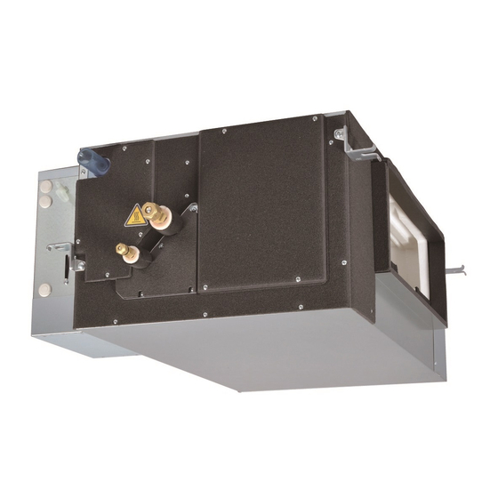
Page 4: Names And Functions Of Components
Incorrect handling of the product may result in injury or Caution damage to properties including buildings and equipment. Caution for injury Prevent water leakage Do not work at a location where you do not have a • Before removing any of the water-related parts, sure footing. -
Page 5: Specifications
[SA (Supply Air) temperature control] Dx-coil unit GUG-02SL-E GUG-03SL-E Connectable LGH-150RVX-E LGH-200RVX-E LGH-80RVX-E LGH-100RVX-E LGH-250RVXT-E Lossnay unit LGH-150RVXT-E LGH-200RVXT-E Connectable PUHZ-ZRP50 PUHZ-ZRP50 PUHZ-ZRP71 PUHZ-ZRP71 PUHZ-ZRP71 outdoor unit Note: GUG-01SL-E cannot be used for the SA temperature control function. ─ 5 ─... -
Page 6: Outside Dimensions
Liquid pipe S Maintenance cover for drain pump, inlet air thermistor and water detecting sensor Model GUG-01SL-E 811 812 330 147 593 520 146 200 100 166 208 192 6.35 12.7 GUG-02SL-E 1033 1034 394 170 600 750 132 250 165 207 258 242 9.52 15.88... -
Page 7: Electrical Wiring Diagram
5. Electrical wiring diagram GUG-01SL-E, GUG-02SL-E, GUG-03SL-E Notes: 1. TB6, TM104 and CN120 shown in dotted lines are field work. 2. Make sure to connect the earth wire. 3. Cut off the power supply (all to the Dx-coil unit, Lossnay unit and outdoor unit) more than five minutes prior to access the electrical parts. -
Page 8: Circuit Board Diagrams
6. Circuit board diagrams Circuit board diagram and check points ( 1 ) Printed circuit board A (PCB A): IF013 Power supply cable connection terminal: TB6 Upper Lower S1, S2, S3 N, L Earth connection Fuse Connection to Outdoor unit Power supply to 3.15 A/250 V CN1 on PCB B... - Page 9 ( 2 ) Printed circuit board B (PCB B): GU-01-E Transformer primary (input): CN2 Transformer 220-240 V/50 Hz secondary 220 V/60 Hz (output): CN4 12 to 17 VAC (PCB A Power supply output: TB6 N, L) PCB B Power supply input: CN1 220-240 V/50 Hz 220 V/60 Hz...
-
Page 10: Troubleshooting
7. Troubleshooting Work precautions • Before starting the service, the power supply isolator must be turned off. Pay sufficient attention to avoid electric shock or injury. • When removing or touching the cables, circuit boards or other parts, make sure to turn off the power supply isolator. - Page 11 See the Lossnay service handbook for individual failures of the Lossnay units, and the outdoor unit service handbook for failures of the outdoor units. Applicable Device Applicable Model Remote controller Dx-coil unit GUG-01SL-E GUG-02SL-E GUG-03SL-E PZ-01RC LGH-150RVX-E, LGH-200RVX-E Connectable LGH-50RVX-E...
- Page 12 7-2 Initial check items Check the following details if the system fails to operate properly after installation is completed. (1) Power supply Check Item Corrective action Is the main power supply of the outdoor unit and Turn the main power supply on. Lossnay unit on? 2 Is the current capacity of the power supply isolator Use an appropriate power supply isolator.
- Page 13 (2) Transmission cables (Remote controller transmission cable, Lossnay connecting cable) Check Item Corrective action 1 Are the designated cables used for the remote control- Use the designated transmission cables. ler transmission cable? (See Table 2.) 2 Is the Lossnay connecting cable securely connected? Connect the cable securely.
- Page 14 (5) LED Indications on PCB A of the Dx-coil unit For description of each LED (LED1, 2, 3) provided on PCB A, refer to the following table. LED1 Indicates whether control power is supplied to PCB A. Make sure that (Power for microcomputer) this LED is always lit.
- Page 15 7-3 Error code and LED display An error code displayed on the remote controller (PZ-01RC or PZ-61DR-E) or the M-NET system controllers, and blinking or illumination of LED11 (green) on PCB B of the Dx-coil unit show the type of an error. This system is comprised of each control circuit of the Dx-coil unit (PCB A and PCB B), Lossnay unit, and outdoor unit.
- Page 16 If an error code is displayed on Dx-coil unit remote controller (PZ-01RC), follow the flowchart below. "P1" displayed on PZ-01RC? Refer to (1). PZ-61DR-E is connected? Refer to (2). 0206, 2600, 2601, 5109, Refer to (3). or 0900 displayed on PZ-61DR-E? Refer to the service handbook of the Lossnay unit for details.
- Page 17 Error code Symptom Cause Corrective action Liquid pipe ther- Faulty connection of thermistor Check the connector connection of CN21 mistor (TH2) connector CN21 on PCB A of the on PCB A. failure Dx-coil unit A break or short in a lead wire for Check the lead wires for thermistor (TH2).
- Page 18 Error code Symptom Cause Corrective action Gas pipe ther- Faulty connection of thermistor Check the connector connection of CN29 mistor (TH5) connector CN29 on PCB A of the on PCB A. failure Dx-coil unit A break or short in a lead wire for Check the lead wires for thermistor (TH5).
- Page 19 Error code Symptom Cause Corrective action Inlet air thermis- Faulty connection of thermistor Check the connector connection of CN23 tor (TH11) failure connector CN23 on PCB A of the on PCB A. Dx-coil unit A break or short in a lead wire for Check the lead wires for thermistor (TH11).
- Page 20 Cause Corrective action (green) 1 blink Temperature The function selection switch (SW1- Dx-coil unit GUG-01SL-E cannot be used control setting 7: Selecting of RA temp. control or for SA temperature control. error SA temp. control) on PCB A of the Set the switch (SW1-7) to ON "RA tem-...
- Page 21 LED11 Symptom Cause Corrective action (green) 2 blinks Drain water Follow the flowchart when "2600" is displayed on Lossnay remote controller (PZ- overflow 61DR-E) or M-NET system controllers. LED11: 2 blinks Error code: “2600” Is the water sensor of the drain pan submerged? After stopping the Dx-coil unit, operate it again.
- Page 22 LED11 Symptom Cause Corrective action (green) 7 blinks Communication Faulty connection of connector Check the connector connection of CN120 error between CN120 (for connecting the Lossnay on PCB B of the Dx-coil unit. the Dx-coil unit unit) on PCB B and Lossnay Faulty connection of connector CN20 Check the connector connection of CN20...
- Page 23 LED11 Symptom Cause Corrective action (green) 9 blinks Errors detect- Some error has occurred in the See the Lossnay service handbook. ed on Lossnay Lossnay unit. control circuit 10 blinks Drain pump Cumulative operation time of the Check the operation of the drain pump, maintenance drain pump has reached 2100 hours.
- Page 24 (3) Error codes displayed on Lossnay remote controller PZ-61DR-E and M-NET system controllers Details about some of the errors that detected on circuit boards of the Dx-coil unit can be checked by LED1 (green) on the control circuit board of the Lossnay unit. When error codes or LED blinking other than the following are shown, refer to the Lossnay service hand- book.
- Page 25 Lossnay unit tween Lossnay and Dx-coil unit. unit and Dx- Lossnay unit Dx-coil unit coil unit LGH-15RVX-E LGH-25RVX-E Unconnectable LGH-35RVX-E LGH-50RVX-E GUG-01SL-E LGH-65RVX-E LGH-80RVX-E GUG-02SL-E LGH-100RVX-E LGH-150RVX-E LGH-200RVX-E LGH-150RVXT-E GUG-03SL-E LGH-200RVXT-E LGH-250RVXT-E Model selection switches (Dx-...
- Page 26 7-4 The system fails to operate properly. (1) If Dx-coil unit remote controller (PZ-01RC) fails to operate properly Symptom Cause Corrective action 1 Nothing is displayed The power of the outdoor unit that is See 7-2 (1). on remote controller connected to the Dx-coil unit is not (PZ-01RC).
- Page 27 Symptom Cause Corrective action 5 Even if you press ON/ Lossnay remote controller (PZ- Check if Lossnay remote controller (PZ- OFF button of remote 61DR-E) was operated almost simul- 61DR-E) was operated simultaneously. controller (PZ-01RC) taneously with the operation of Dx- to operate or stop coil unit remote controller (PZ-01RC).
- Page 28 Symptom Cause Corrective action 12 Even when the target Temperature range that can be set For details, see the operating instructions temperature of re- differs depending on control types of the Dx-coil unit. mote controller (PZ- (RA temp. control or SA temp. con- 01RC) is changed, trol) or operation modes of the Dx- the temperature...
- Page 29 (2) If the Dx-coil unit fails to operate properly Symptom Cause Corrective action Operation mode of the Dx-coil unit is Check the operation mode by Dx-coil unit 1 Air blowing through set to "Fan." remote controller (PZ-01RC). the Dx-coil unit can- not be cooled or Target temperature of the Dx-coil unit Check the temperature setting by Dx-coil...
- Page 30 Symptom Cause Corrective action 1 Air blowing through DIP switches (function selection Check the setting of the function selection the Dx-coil unit can- switches) on PCB A of the Dx-coil switches on PCB A of the Dx-coil unit. not be cooled or unit are not set according to specifi- warmed.
- Page 31 Symptom Cause Corrective action In the case of interlocking with the • Set the operation mode and target tem- 2 The room is too cool City Multi indoor unit, operation mode perature of the Dx-coil unit by using the or too warm. or target temperature is set by the Dx-coil unit remote controller (PZ-01RC) remote controller for the City Multi...
- Page 32 (3) If the Lossnay unit to which the Dx-coil unit is connected fails to operate properly *For symptoms other than the following, see the Lossnay service handbook. Symptom Cause Corrective action 1 The Lossnay unit does The function selection switch (SW7-1: Check the function selection switch not operate even when Setting whether or not the Dx-coil unit...
- Page 33 Symptom Cause Corrective action 6 When the Indoor nega- The function selection switch (SW7-2 When the Indoor negative pressure tive pressure setting of (and SW7-3): Selection of the opera- setting is enabled, set to "Fan speed the Lossnay unit is ena- tion mode from "Temp.
- Page 34 Symptom Cause Corrective action 5 When the system is operated, Some error, which can be detected See 7-3 (3). an error code is displayed on only during operation, has occurred. the remote controllers. 6 Even though no error code is The error code "P1"...
-
Page 35: Overhauling Procedures
8. Overhauling procedures Work precautions • When touching the electric components such as circuit boards, do not touch the components for more than five minutes after power-off, and then start working. When shut down the power of the Dx-coil unit for repair working, make sure to turn off the power to the Lossnay unit as well. - Page 36 4 Remove PCB A from the support pieces (four locations) on each corner. (Pinch the support pieces as shown in the right picture.) Push Push Note Refer to section (9) for installing the circuit board. Support piece ( 3 ) Remove PCB B (GU-01-E), transformer, and ferrite core 1 Remove the control cover.
- Page 37 1 Remove the drain piping from the socket of the drain pump assembly. 2 Unscrew the screws to remove the drain socket cover. For GUG-01SL-E and GUG-02SL-E Drain socket cover (Seven special screws 4×14, indicated by ) (See the photo below.)
- Page 38 3 Unscrew the screws (four PTT screws 4×8, indicated by and shown in the photo below) to remove the drain pump fixing plate. For GUG-01SL-E and GUG-02SL-E For GUG-03SL-E Drain pump fixing plate Drain pump fixing plate 4 Unscrew the screws (two PT screws 4×8, indicated by Drain pump assembly ...
- Page 39 1 Remove the drain socket cover. → See (4) 2. 2 Unscrew the screws (two PTT screws 4×8, indicated by and shown in the photo below), and pull out the thermistor fixing plate. For GUG-01SL-E and GUG-02SL-E For GUG-03SL-E Thermistor fixing plate...
- Page 40 (7) Remove the thermistor (TH9: Supply air temperature thermistor) Note GUG-01SL-E is not equipped with the thermistor (TH9). For GUG-02SL-E 1 Unscrew the screws (four special screws 4×14, indicated Maintenance cover E by and shown in the photo below) to remove the main- tenance cover E.
- Page 41 For GUG-03SL-E 1 Unscrew the screws (five special screws 4×14, indicated Maintenance cover C by and shown in the photo below) to remove mainte- nance cover C. 2 Unscrew the screws (two PTT screws 4×8, indicated by Thermistor fixing plate ...
- Page 42 (8) Remove the thermistors (TH2: Liquid pipe temperature thermistor, TH5: Gas pipe temperature thermistor) For GUG-01SL-E and GUG-02SL-E 1 Remove all the covers from the Dx-coil unit. Maintenance cover B Maintenance cover E a. Unscrew the screws (seven special screws 4×14, shown in the photo below) to remove the drain socket cover.
- Page 43 For GUG-03SL-E 1 Remove the following covers from the Dx-coil unit. Drain socket cover Maintenance cover C a. Unscrew the screws (six special screws 4×14, shown in the photo below) to remove the drain socket cover. → See (4) 2 . b.
- Page 44 Notes: *1 Be aware of the polarity of TB6, and pay attention not to make wrong connection. *2 GUG-01SL-E is not equipped with SA thermistor (TH9). Assembly precautions • Securely connect the connectors between CN82/CN20 on PCB A and CN6 on PCB B. Make sure to con- nect all the connectors, and check for contact failure, wrong connection, or the like.
- Page 45 PCB B of the Dx-coil unit Follow the table below for setting the model selection switches (SW11-9 and SW11-10) SW11 SW11-9 SW11-10 Contents □ □ New circuit board for replacement □ □ GUG-01SL-E □ □ GUG-02SL-E □ □ GUG-03SL-E □ □ □ □...
- Page 46 Note: SW6 setting differs according to the model. □ □ Model SW6-1 SW6-2 SW6-3 SW6-4 □ □ LGH-50RVX-E □ □ LGH-65RVX-E □ □ LGH-80RVX-E LGH-100RVX-E LGH-150RVX-E LGH-200RVX-E LGH-150RVXT-E LGH-200RVXT-E : Factory setting LGH-250RVXT-E 3Function settings by Lossnay remote controller (PZ-61DR-E) When Lossnay remote controller (PZ-61DR-E) is used, enter the setting data of the functions set by PZ-61DR-E.
-
Page 47: Parts Catalog
9. Parts catalog Please note the following when using the parts catalog. 1. When ordering parts, always indicate the part number, part name, and the number of parts required. 2. It may take time for you to receive the parts. Make an inquiry about a rush order. 3. - Page 48 GUG-01SL-E 7 pcs. 2 pcs. 4 pcs. 2 pcs. 4 pcs. 5 pcs. 4 pcs. 2 pcs. <Standard screws> PRC screw 4x30 Symbol Screw name 6 pcs. 2 pcs. 2 pcs. 1 pc. 1 pc. PTT screw 4x8 2 pcs.
- Page 49 GUG-01SL-E Critical Q'ty Name of part Parts No. Remarks pcs/unit safety Flange W50 004 609 Hanger L W36 002 380 Hanger R W50 004 380 Drain pump assembly W50 012 319 Drain hose set Maintenance cover B W50 012 695...
- Page 50 4 pcs. 2 pcs. 2 pcs. 2 pcs. 12 pcs. 2 pcs. <Standard screws> Symbol Screw name PTT screw 4x8 PT screw 4x8 ─ 50 ─ GUG-01SL-E...
- Page 51 GUG-01SL-E Critical Q'ty Name of part Parts No. Remarks pcs/unit safety 31 Special screw 4x8 W00 000 089 32 Control cover W50 012 698 33 Side plate W50 012 715 34 Cord bush W00 000 270 35 Cord band W00 000 258...
- Page 52 PUMP (WHITE) LED6 CN120 SW11 LED7 (GREEN) To Lossnay (CN20) CN10 WATER (RED) SENSOR CN23 CN21 CN29 (WHITE) (YELLOW) CN22 CN82 CN20 TM104 CN20:RED (WHITE) CN23:BROWN TH11 CN29:BLACK CN22:BLUE Others: WHITE Dedicated remote controller PZ-01RC (Accessory) ─ 52 ─ GUG-01SL-E...
- Page 53 GUG-01SL-E Critical Q'ty Name of part Parts No. Remarks pcs/unit safety 61 Lead wire W50 012 214 CN5-CN105 62 Lead wire W50 012 215 CN6-CN22,CN82,CN20 63 Thermistor (TH11) W50 012 217 64 Thermistor (TH2、TH5) W50 012 222 ...
- Page 54 GUG-02SL-E 7 pcs. 2 pcs. 4 pcs. 2 pcs. 4 pcs. 5 pcs. 4 pcs. 2 pcs. PRC screw 4x30 <Standard screws> Symbol Screw name 6 pcs. 2 pcs. 2 pcs. 1 pc. 1 pc. PTT screw 4x8 2 pcs. PT screw 4x12 Special screw 4x16 PT screw 5x10...
- Page 55 GUG-02SL-E Critical Q'ty Name of part Parts No. Remarks pcs/unit safety Flange W50 004 610 Hanger L W36 002 380 Hanger R W50 004 380 Drain pump assembly W50 012 320 Drain hose set Maintenance cover B W50 012 695 Maintenance cover A W50 012 694 Maintenance cover E...
- Page 56 4 pcs. 2 pcs. 2 pcs. 2 pcs. 12 pcs. 2 pcs. <Standard screws> Symbol Screw name PTT screw 4x8 PT screw 4x8 ─ 56 ─ GUG-02SL-E...
- Page 57 GUG-02SL-E Critical Q'ty Name of part Parts No. Remarks pcs/unit safety 31 Special screw 4x8 W00 000 089 32 Control cover W50 012 698 33 Side plate W50 012 715 34 Cord bush W00 000 270 35 Cord band W00 000 258 36 Lead wire clip W00 000 238 37 Circuit board...
- Page 58 To outdoor unit Printed circuit board A (PCB A) TAB1 (IF013) TRANS LED1 LED5 LED4 Printed circuit LED3 board B Fuse 3.15 A 250 V (PCB B) LED2 (GU-01-E) Fuse (RED) 5 A 250 V CN105 LED12 (RED) DRAIN LED11 PUMP (WHITE) LED6...
- Page 59 GUG-02SL-E Critical Q'ty Name of part Parts No. Remarks pcs/unit safety 61 Lead wire W50 012 214 CN5-CN105 62 Lead wire W50 012 215 CN6-CN22,CN82,CN20 63 Thermistor (TH11) W50 012 218 64 Thermistor (TH2、TH5) W50 012 222 ...
- Page 60 GUG-03SL-E 6 pcs. 2 pcs. 5 pcs. 4 pcs. 6 pcs. 3 pcs. 5 pcs. 2 pcs. 6 pcs. <Standard screws> PRC screw 4x30 Symbol Screw name 6 pcs. 2 pcs. 2 pcs. 1 pc. 1 pc. PTT screw 4x8 2 pcs.
- Page 61 GUG-03SL-E Critical Q'ty Name of part Parts No. Remarks pcs/unit safety Flange W50 004 734 Hanger R W50 004 380 Hanger L W36 002 380 Drain socket cover W50 012 699 Special screw 4x14 W00 000 198 Cord band W00 000 292 301mm Heat insulator W50 012 703...
- Page 62 4 pcs. 2 pcs. 2 pcs. 2 pcs. 12 pcs. 2 pcs. <Standard screws> Symbol Screw name PTT screw 4x8 PT screw 4x8 ─ 62 ─ GUG-03SL-E...
- Page 63 GUG-03SL-E Critical Q'ty Name of part Parts No. Remarks pcs/unit safety 31 Special screw 4x8 W00 000 089 32 Control cover W50 012 698 33 Side plate W50 012 715 34 Cord bush W00 000 270 35 Cord band W00 000 258 36 Lead wire clip W00 000 238 37 Circuit board...
- Page 64 To outdoor unit Printed circuit board A (PCB A) TAB1 (IF013) TRANS LED1 LED5 LED4 Printed circuit board B LED3 Fuse 3.15 A 250 V (PCB B) LED2 (GU-01-E) Fuse (RED) 5 A 250 V CN105 LED12 (RED) DRAIN LED11 PUMP (WHITE) LED6...
- Page 65 GUG-03SL-E Critical Q'ty Name of part Parts No. Remarks pcs/unit safety 61 Lead wire W50 012 214 CN5-CN105 62 Lead wire W50 012 215 CN6-CN22,CN82,CN20 63 Thermistor (TH11) W50 012 217 64 Thermistor (TH2、TH5) W50 012 223 ...