Table of Contents
Advertisement
Quick Links
Advertisement
Table of Contents

Related Manuals for PPI claveX Series


Summary of Contents for PPI claveX Series
- Page 1 Clave Autoclave Controller User Manual...
- Page 2 Clave User Manual CONTENTS 1. FRONT PANEL LAYOUT 2. BASIC OPERATION 3. SET UP MODE : ACCESS & OPERATION 4. INPUT / OUTPUT CONFIGURATION PARAMETERS 5. SOAK TIMER PARAMETERS & OPERATION DETAILS SUPERVISORY PARAMETERS ELECTRICAL CONNECTIONS...
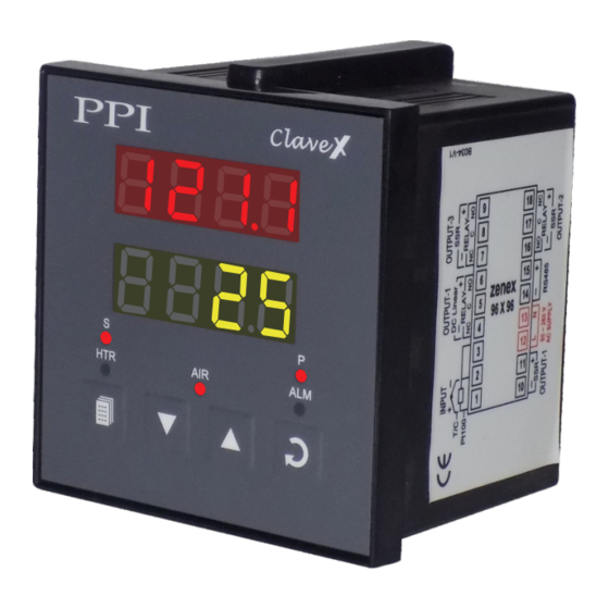
- Page 3 Clave User Manual Section 1 FRONT PANEL LAYOUT Figure 1.1 (a) : 48 X 48 Version Clave Upper Readout Lower Readout Lower Readout Display Mode Indicators Air Outlet Status Heater Status Alarm Status PAGE Key ENTER Key DOWN Key UP Key Figure 1.1 (b) : 96 X 96 Version Clave 96 Upper Readout...
- Page 4 Clave User Manual Table 1.1 Indicator Status Indicates Heater On/Off status. Indicates Air Outlet valve On/Off status. Flashes while the Alarm is active. These two indicators together indicate the parameter name whose value is currently being displayed on the Lower Readout. What Lower Readout Indicates (Start) message.
- Page 5 Clave User Manual Section 2 BASIC OPERATIONS POWER-UP Upon power-up all displays and indicators are lit on for approximately 3 seconds. This is followed by the indication of the controller model name on the Upper Readout and the firmware version on the Lower Readout, for approximately 1 second.
- Page 6 Clave User Manual Notes 1) If the controller is supplied with ‘Water Level Input’ option, the running cycle is aborted if Low water level is detected. Also, a new start command is not accepted until the water level error is removed. While the level is low, the Lower Readout flashes the message (Low Level).
- Page 7 Clave User Manual Use UP/DOWN keys to adjust the value and then press ENTER key to store the set value and scroll to the next parameter. The controller automatically reverts to MAIN Display Mode upon scrolling through the last operator parameter. Alternatively, use PAGE key to return to MAIN Display Mode.
- Page 8 Clave User Manual Section 3 SET-UP MODE : ACCESS AND OPERATION The various parameters are arranged in different groups, called PAGES, depending upon the functions they represent. Each group is assigned a unique numeric value, called PAGE NUMBER, for its access. The parameters are always presented in a fixed format: The Lower Readout displays the parameter prompt (Identification Name) and the Upper Readout displays the set value.
- Page 9 Clave User Manual MASTER LOCKING The controller facilitates locking all the PAGES (except Operator PAGE) by applying Master Lock Code. Under Locking, the parameters are available for view only and cannot be adjusted. The Master Lock, however does not lock the operator parameters .
- Page 10 Clave User Manual Section 4 I / O CONFIGURATION PARAMETERS Table 4.1 Settings Parameter Description (Default Value) HYSTERESIS 1 to 999°C or Sets a differential (dead) band between the ON and OFF heater 0.1 to 99.9°C states. Keep it large enough to avoid frequent switching of the (Default : heater without losing the desired control accuracy.
- Page 11 Clave User Manual Section 5 SOAK TIMER PARAMETERS (Refer end of this section for detailed Soak Timer Operation) Table 5.1 Settings Parameter Description (Default Value) SOAK TIME 1 to 999 Minutes The time duration in ‘Minutes’ for which the autoclave temperature (Default : 20) is maintained at the set control setpoint value.
- Page 12 Clave User Manual SOAK TIMER OPERATION Figure 5.1 Start Band PV enters start band, Timer count down starts Time Set Time Basic Operation The Soak Timer is essentially a Setpoint Dependent Timer. That is, after issuance of Start Command, the count down starts only after the Temperature Value reaches within timer ‘Start Band’.
- Page 13 Clave User Manual Section 6 PAGE-11 : SUPERVISORY PARAMETERS Table 6.1 Settings Parameter Description (Default Value) OFFSET FOR TEMPERATURE VALUE -1999 to 9999 or This parameter adds positive or negative offset to the Measured -199.9 to 999.9 Temperature Value for removal of thermal gradient or known (Default : sensor error.
- Page 14 Clave User Manual Settings Parameter Description (Default Value) BAUD RATE 1200 (Available for Utility Option ‘Serial Comm.’ only) 2400 This parameter defines the communication speed expressed in “Bits per second”. The Baud Rate must be set to match the Baud 4800 Rate set for the Master Device.
- Page 15 Clave User Manual Section 7 ELECTRICAL CONNECTIONS Refer connection diagram shown on the left side of the enclosure. The diagram shows the terminals viewed from the REAR SIDE with the controller label upright. Figure 7.1 48 X 48 96 X 96 9 10 48X48 96X96...
- Page 16 Clave User Manual OUTPUT- 2 (Air Outlet Control) Output-2 can be configured as either Relay or SSR drive through appropriate jumper settings. Figure 7.4(a) 48X48 96X96 Relay Output Potential-free Relay changeover contacts NO (Normally Open) and C (Common) rated 10A/240 VAC (resistive load).
- Page 17 Process Precision Instruments 101, Diamond Industrial Estate, Navghar, Vasai Road (E), Dist. Palghar - 401 210.Maharashtra, India 0250 - 2391722/33/37/42 07498799226, 09321985369 sales@ppiindia.net, support@ppiindia.net w w w . p p i i n d i a . n e t...
Need help?
Do you have a question about the claveX Series and is the answer not in the manual?
Questions and answers