
Related Manuals for PPI HumiTherm-c Series


Summary of Contents for PPI HumiTherm-c Series
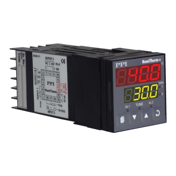
- Page 1 HumiTherm-c Composite ‘Temperature + Humidity’ Self Tune PID Controller Version : Dry-Bulb RTD Pt100, 3-wire Wet-Bulb RTD Pt100, 3-wire Version : RTD Pt100, 3-wire for Temperature DC Linear (Voltage) for Humidity (PID) User Manual...
-
Page 2: Table Of Contents
HumiTherm-c User Manual CONTENTS For Dry-Wet 1. FRONT PANEL LAYOUT 2. BASIC OPERATION 3. PAGES AND PARAMETERS TEMPERATURE PARAMETERS RELATIVE HUMIDITY PARAMETERS SUPERVISORY PARAMETERS 7. OP3 FUNCTION PARAMETER 8. UTILITY PARAMETERS COMPRESSOR OPERATION AND POWER INDIC HARDWARE ASSEMBLY & CONFIGURATIONS MECHANICAL INSTALLATION ELECTRICAL CONNECTIONS For Temp+RH... -
Page 3: Front Panel Layout
HumiTherm-c (Dry-Wet) User Manual Section 1 FRONT PANEL LAYOUT The controller front panel comprises of digital readouts, LED indicators and tactile keys as shown in Figure 1.1 below. Figure 1.1 HumiTherm-c °C Upper Readout Lower Readout Output-1 Indicator Tune Indicator Output-2 Indicator Alarm -1 Indicator Alarm-2 Indicator... - Page 4 HumiTherm-c (Dry-Wet) User Manual KEYS There are four tactile keys provided on the front panel for configuring the controller and setting-up the parameter values. The Table 1.2 below lists each key (identified by the front panel symbol) and the associated function. Table 1.2 Symbol Function...
-
Page 5: Basic Operation
HumiTherm-c (Dry-Wet) User Manual Section 2 BASIC OPERATIONS POWER-UP Upon switching on the power to the controller, all displays and indicators are lit on for approximately 3 seconds during which time the controller runs through a self-test sequence. This is followed by the indication of the controller model name the Upper Readout and the firmware version on the Lower Readout, for approximately 1 second. - Page 6 HumiTherm-c (Dry-Wet) User Manual TEMPERATURE-ONLY MODE The controller can be configured to operate in Temperature-only mode by setting the %RH SP value to 0. In this mode, the controller controls only the Dry Bulb Temperature at the set value through Heater Control Output-1. The %RH Control Output- 2 is kept off.
-
Page 7: Pages And Parameters
HumiTherm-c (Dry-Wet) User Manual Section 3 PAGES AND PARAMETERS ORGANIZATION The controller requires various user settings that determine how the controller will function or operate. These settings are called Parameters. The parameters are always presented in a fixed format: The Lower Readout displays the parameter prompt (Identification Tag) and the Upper Readout displays the set value. - Page 8 HumiTherm-c (Dry-Wet) User Manual adjusting a numeric value; depressing the UP/DOWN key once, increases/decreases the parameter value by one digit. For parameters having a series of options, depressing the UP/DOWN key once takes you to the next/previous option. In each case, keeping the UP/DOWN key pressed speeds up the rate. If the value reaches the maximum / minimum settable value/option, the Upper Readout flashes and the UP (if maximum value is reached) or DOWN (if minimum value is reached) key has no effect.
- Page 9 HumiTherm-c (Dry-Wet) User Manual Unlocking 1. Press and release PAGE key while the controller is in the MAIN Display Mode. The Lower Readout shows PAGE and the Upper Readout shows 0. 2. Adjust the Upper Readout to the value 123 using UP/DOWN keys. 3.
-
Page 10: Temperature Parameters
HumiTherm-c (Dry-Wet) User Manual Section 4 TEMPERATURE PARAMETERS The PAGE-10 lists Alarm and Control related parameters for Dry-Bulb Temperature. The Table 4.1 below describes each parameter. Table 4.1 Settings Parameter Description (Default Value) ALARM-1 BAND Sets symmetrical positive and negative deviation (offset) limits from Temperature control setpoint for both High and Low Alarm-1 0.3 to 25.0°C activation. -
Page 11: Relative Humidity Parameters
HumiTherm-c (Dry-Wet) User Manual Section 5 RELATIVE HUMIDITY (% RH) PARAMETERS The PAGE-11 lists Alarm and Control related parameters for %RH (Wet-Bulb). The Table 5.1 below describes each parameter. Table 5.1 Settings Parameter Description (Default Value) ALARM-2 BAND Sets symmetrical positive and negative deviation (offset) limits from %RH control setpoint for both High and Low Alarm-2 0.3 to 25.0% activation. -
Page 12: Supervisory Parameters
HumiTherm-c (Dry-Wet) User Manual Section 6 SUPERVISORY PARAMETERS The Supervisory Parameters provided on PAGE-12 facilitate supervisory control over the operator level. The Table 6.1 below describes each parameter. Table 6.1 Settings Parameter Description (Default Value) SP ADJUSTMENT ON PAGE-0 Enable Supervisory permission for Temperature and %RH setpoint Disable editing on Operator Page (PAGE-0). -
Page 13: Op3 Function Parameter
HumiTherm-c (Dry-Wet) User Manual Section 7 OP3 FUNCTION PARAMETERS The OP3 Function Parameters presented on PAGE-13 allow the user to configure the Output-3 (OP3) Function as Alarm or Compressor Control. The Table 7.1 below describes each parameter. Table 7.1 Settings Parameter Description (Default Value) OUTPUT-3 FUNCTION SELECTION... -
Page 14: Utility Parameters
HumiTherm-c (Dry-Wet) User Manual Section 8 UTILITY PARAMETERS The Utility Parameters are grouped on PAGE-33 and allow the user to set the Compressor Control Strategy and the Zero- Offset values for Temperature and the Relative Humidity (RH) values. The Table 8.1 below describes each parameter. Table 8.1 Settings Parameter Description... - Page 15 HumiTherm-c (Dry-Wet) User Manual Figure 8.1 Figure 8.2 Dry Bulb Setpoint (°C.SP) Compressor Setpoint (CP.SP) Compressor Setpoint (CP.SP) Dry Bulb Setpoint (°C.SP) Compressor ON Compressor OFF Dry Bulb SP < Compressor SP Dry Bulb SP ≥ Compressor SP Compressor ON Compressor OFF This strategy eliminates the dependency on the user for switching off the compressor (for saving valuable electrical energy) when not required.
-
Page 16: Compressor Operation And Power Indic
HumiTherm-c (Dry-Wet) User Manual Section 9 COMPRESSOR OPERATION & POWER INDICATION The PAGE-1 allows the operator to select the compressor switching as ‘Automatic’ or ‘Manual’, through a parameter ‘Compressor Operation’. This parameter is available and applicable only if the ‘Compressor Control’ is selected for ‘Output-3 (OP3) Function’... -
Page 17: Hardware Assembly & Configurations
HumiTherm-c (Dry-Wet) User Manual Section 10 HARDWARE ASSEMBLY & CONFIGURATIONS OUTER CASE Figure 10.1 Ventilations Rear Terminals Panel Mounting Clamp Panel Sealing Gasket N / C + 5 V N / O Bezel ° C Enclosure S E N Connection Diagram Ratchets Front Label Pullout Grip... - Page 18 HumiTherm-c (Dry-Wet) User Manual Figure 10.2. ‘UP’ inscribed on topside N / C + 5 V N / O Bezel S E N ° C P l a c i n Front Label Pullout Grip Placing Back 1. Hold the bezel with the front label upright. 2.
- Page 19 HumiTherm-c (Dry-Wet) User Manual MOUNTING PLUG-IN MODULES The controller supports Input-2 (DC Linear Voltage) module which is mandatary for measuring Relative Humidity (%RH) Value and two optional plug-in modules, viz. Output-3 (Relay/SSR) module and Serial Communication module. These modules are either pre-fitted while the controller is shipped from the factory (if ordered with the basic configuration) or can be fitted by the user if ordered separately.
- Page 20 HumiTherm-c (Dry-Wet) User Manual Figure 10.5 Mounting Output-3 Module Plug & Socket Connector Output Module Projections Slots Power Supply Board H u m i T h e r m - Front Label Upright For plugging out the module(s), follow the steps below: 1.
-
Page 21: Mechanical Installation
HumiTherm-c (Dry-Wet) User Manual Section 11 MECHANICAL INSTALLATION OUTER DIMENSIONS AND PANEL CUTOUT Figure 11.1 48mm (1.89in) HumiTherm-c °C 45 X 45 mm -0, +0.5 mm (1.77 X 1.77 in) (-0, +0.02 in) Front View Panel Cutout The Figure 11.1 shows the controller front outer dimensions and the panel cutout requirements. for a single controller and also the minimum spacing recommended if several controllers are required to be mounted on a single panel. -
Page 22: Electrical Connections
HumiTherm-c (Dry-Wet) User Manual Section 12 ELECTRICAL CONNECTIONS WARNING MISHANDLING / NEGLIGENCE CAN RESULT IN PERSONAL DEATH OR SERIOUS INJURY. 1. The user must rigidly observe the Local Electrical Regulations. 2. Do not make any connections to the unused terminals for making a tie-point for other wires (or for any other reasons) as they may have some internal connections. - Page 23 HumiTherm-c (Dry-Wet) User Manual DESCRIPTIONS INPUT-1 : Dry-Bulb RTD Pt100, 3-Wire (Terminals 1, 2 and 3) Figure 12.2 (a) Connect single leaded end of RTD bulb to terminal 1 and the double leaded ends to terminal 2 and 3 (interchangeable) as shown in Figure 12.2 (a). Use copper conductor leads of very low resistance for RTD connections.
- Page 24 HumiTherm-c (Dry-Wet) User Manual Relay Potential-free Relay changeover contacts N/O (Normally Open), C (Common) and N/C (Normally Close); rated 2A/240 VAC (resistive load) are provided as Relay output. Use external auxiliary device like contactor with appropriate contact rating for driving the actual load. Drive for SSR DC Voltage level is generated for switching the external SSR (Solid State Relay).
- Page 25 HumiTherm-c (Temp+RH) User Manual HumiTherm-c Temp+RH...
-
Page 26: Front Panel Layout
HumiTherm-c (Temp+RH) User Manual Section 1 FRONT PANEL LAYOUT The controller front panel comprises of digital readouts, LED indicators and tactile keys as shown in Figure 1.1 below. Figure 1.1 HumiTherm-c °C Upper Readout Lower Readout Output-1 Indicator Tune Indicator Output-2 Indicator Alarm -1 Indicator Alarm-2 Indicator... - Page 27 HumiTherm-c (Temp+RH) User Manual Indicator Function Indicates Tuning or Compressor ON/OFF status. • Flashes while the controller is executing the Tuning operation. • Glows continuously while the Compressor is ON. • Remains OFF, if not executing the Tuning operation or Compressor is OFF.
-
Page 28: Basic Operation
HumiTherm-c (Temp+RH) User Manual Section 2 BASIC OPERATIONS POWER-UP Upon switching on the power to the controller, all displays and indicators are lit on for approximately 3 seconds during which time the controller runs through a self-test sequence. This is followed by the indication of the controller model name the Upper Readout and the firmware version on the Lower Readout, for approximately 1 second. - Page 29 HumiTherm-c (Temp+RH) User Manual Tuning operation, the front panel indicator TUN flashes. The user is advised not to disturb the process or alter any parameter values while the tuning is in progress. The TUN indicator automatically turns OFF upon completion of Tuning Procedure. The controller reverts to the MAIN Display Mode and starts maintaining the Temperature and RH values (PV) at their respective Setpoints.
-
Page 30: Pages And Parameters
HumiTherm-c (Temp+RH) User Manual Section 3 PAGES AND PARAMETERS ORGANIZATION The controller requires various user settings that determine how the controller will function or operate. These settings are called Parameters. The parameters are always presented in a fixed format: The Lower Readout displays the parameter prompt (Identification Tag) and the Upper Readout displays the set value. - Page 31 HumiTherm-c (Temp+RH) User Manual adjusting a numeric value; depressing the UP/DOWN key once, increases/decreases the parameter value by one digit. For parameters having a series of options, depressing the UP/DOWN key once takes you to the next/previous option. In each case, keeping the UP/DOWN key pressed speeds up the rate. If the value reaches the maximum / minimum settable value/option, the Upper Readout flashes and the UP (if maximum value is reached) or DOWN (if minimum value is reached) key has no effect.
- Page 32 HumiTherm-c (Temp+RH) User Manual Unlocking 1. Press and release PAGE key while the controller is in the MAIN Display Mode. The Lower Readout shows PAGE and the Upper Readout shows 0. 2. Adjust the Upper Readout to the value 123 using UP/DOWN keys. 3.
-
Page 33: Temperature Parameters
HumiTherm-c (Temp+RH) User Manual Section 4 TEMPERATURE PARAMETERS The PAGE-10 lists Alarm and Control related parameters for Temperature. The Table 4.1 below describes each parameter. Table 4.1 Settings Parameter Description (Default Value) ALARM-1 BAND Sets symmetrical positive and negative deviation (offset) limits from Temperature control setpoint for both High and Low Alarm-1 0.3 to 25.0°C activation. -
Page 34: Relative Humidity Parameters
HumiTherm-c (Temp+RH) User Manual Section 5 RELATIVE HUMIDITY (%RH) PARAMETERS The PAGE-11 lists Alarm and Control related parameters for %RH. The Table 5.1 below describes each parameter. Table 5.1 Settings Parameter Description (Default Value) ALARM-2 BAND Sets symmetrical positive and negative deviation (offset) limits from %RH control setpoint for both High and Low Alarm-2 0.3 to 25.0% activation. -
Page 35: Supervisory Parameters
HumiTherm-c (Temp+RH) User Manual Section 6 SUPERVISORY PARAMETERS The Supervisory Parameters provided on PAGE-12 facilitate supervisory control over the operator level. The Table 6.1 below describes each parameter. Table 6.1 Settings Parameter Description (Default Value) SP ADJUSTMENT ON PAGE-0 Enable Supervisory permission for temperature and %RH setpoint editing Disable on Operator Page (PAGE-0). -
Page 36: Op3 Function Parameter
HumiTherm-c (Temp+RH) User Manual Section 7 OP3 FUNCTION PARAMETERS The OP3 Function Parameters presented on PAGE-13 allow the user to configure the Output-3 (OP3) Function as Alarm or Compressor Control. The Table 7.1 below describes each parameter. Table 7.1 Settings Parameter Description (Default Value) OUTPUT-3 FUNCTION SELECTION... -
Page 37: Utility Parameters
HumiTherm-c (Temp+RH) User Manual Section 8 UTILITY PARAMETERS The Utility Parameters are grouped on PAGE-33 and allow the user to set the Compressor Control Strategy and the Zero- Offset values for Temperature and the Relative Humidity (RH) values. The Table 8.1 below describes each parameter. Table 8.1 Settings Parameter Description... - Page 38 HumiTherm-c (Temp+RH) User Manual Figure 8.1 Figure 8.2 Dry Bulb Set-point (°C.SP) Compressor Set-point (CP.SP) Compressor Set-point (CP.SP) Dry Bulb Set-point (°C.SP) Compressor ON Compressor OFF Dry Bulb SP < Compressor SP Dry Bulb SP ≥ Compressor SP Compressor ON Compressor OFF This strategy eliminates the dependency on the user for switching off the compressor (for saving valuable electrical energy) when not required.
- Page 39 HumiTherm-c (Temp+RH) User Manual %RH LOW AND %RH HIGH The controller is calibrated for 0 to 5 VDC input for % RH. The transmitter output signal, however, may be any voltage between 0 to 5 VDC (for e.g. 0 to 1 VDC, 1 to 3.6 VDC, 0 to 3.3 VDC etc.). The value for ‘Range Low’ and ‘Range High’ parameters must be corresponding to 0 and 5 VDC only.
-
Page 40: Compressor Operation And Power Indic
HumiTherm-c (Temp+RH) User Manual Section 9 COMPRESSOR OPERATION & POWER INDICATION The PAGE-1 allows the operator to select the compressor switching as ‘Automatic’ or ‘Manual’, through a parameter ‘Compressor Operation’. This parameter is available and applicable only if the ‘Compressor Control’ is selected for ‘Output-3 (OP3) Function’... -
Page 41: Hardware Assembly & Configurations
HumiTherm-c (Temp+RH) User Manual Section 10 HARDWARE ASSEMBLY & CONFIGURATIONS OUTER CASE Figure 10.1 Ventilations Rear Terminals Panel Mounting Clamp Panel Sealing Gasket N / C + 5 V N / O Bezel ° C Enclosure S E N Connection Diagram Ratchets Front Label Pullout Grip... - Page 42 HumiTherm-c (Temp+RH) User Manual Figure 10.2. ‘UP’ inscribed on topside N / C + 5 V N / O Bezel S E N ° C P l a c i n Front Label Pullout Grip Placing Back 1. Hold the bezel with the front label upright. 2.
- Page 43 HumiTherm-c (Temp+RH) User Manual MOUNTING PLUG-IN MODULES The controller supports Input-2 (DC Linear Voltage) module which is mandatary for measuring Relative Humidity (%RH) Value and two optional plug-in modules, viz. Output-3 (Relay/SSR) module and Serial Communication module. These modules are either pre-fitted while the controller is shipped from the factory (if ordered with the basic configuration) or can be fitted by the user if ordered separately.
- Page 44 HumiTherm-c (Temp+RH) User Manual Figure 10.5 Mounting Output-3 Module Plug & Socket Connector Output Module Projections Slots Power Supply Board H u m i T h e r m - Front Label Upright For plugging out the module(s), follow the steps below: 1.
-
Page 45: Mechanical Installation
HumiTherm-c (Temp+RH) User Manual Section 11 MECHANICAL INSTALLATION OUTER DIMENSIONS AND PANEL CUTOUT Figure 11.1 48mm (1.89in) HumiTherm-c °C 45 X 45 mm -0, +0.5 mm (1.77 X 1.77 in) (-0, +0.02 in) Front View Panel Cutout The Figure 11.1 shows the controller front outer dimensions and the panel cutout requirements. for a single controller and also the minimum spacing recommended if several controllers are required to be mounted on a single panel. -
Page 46: Electrical Connections
HumiTherm-c (Temp+RH) User Manual Section 12 ELECTRICAL CONNECTIONS WARNING MISHANDLING / NEGLIGENCE CAN RESULT IN PERSONAL DEATH OR SERIOUS INJURY. 1. The user must rigidly observe the Local Electrical Regulations. 2. Do not make any connections to the unused terminals for making a tie-point for other wires (or for any other reasons) as they may have some internal connections. - Page 47 HumiTherm-c (Temp+RH) User Manual DESCRIPTIONS INPUT-1 : RTD Pt100, 3-Wire (Terminals 1, 2 and 3) Figure 12.2 (a) The controller accepts 3-wire RTD Pt100 as input for measuring Dry Bulb Temperature Value. Connect single leaded end of RTD bulb to terminal 1 and the double leaded ends to terminal 2 and 3 (interchangeable) as shown in Figure 12.2 (a).
- Page 48 HumiTherm-c (Temp+RH) User Manual Relay Potential-free Relay changeover contacts N/O (Normally Open), C (Common) and N/C (Normally Close); rated 2A/240 VAC (resistive load) are provided as Relay output. Use external auxiliary device like contactor with appropriate contact rating for driving the actual load. Drive for SSR DC Voltage level is generated for switching the external SSR (Solid State Relay).
- Page 49 Process Precision Instruments 101, Diamond Industrial Estate, Navghar, Vasai Road (E), Dist. Palghar - 401 210.Maharashtra, India 0250 - 2391722/33/37/42 07498799226, 09321985369 sales@ppiindia.net, support@ppiindia.net w w w . p p i i n d i a . n e t...
Need help?
Do you have a question about the HumiTherm-c Series and is the answer not in the manual?
Questions and answers