Advertisement
Quick Links
Thank you for purchasing a Sealey product. Manufactured to a high standard this product will, if used according to these instructions
and properly maintained, give you years of trouble free performance.
IMPORTANT: PLEASE READ THESE INSTRUCTIONS CAREFULLY. NOTE THE SAFE OPERATIONAL REQUIREMENTS, WARNINGS & CAUTIONS.
USE THE PRODUCT CORRECTLY AND WITH CARE FOR THE PURPOSE FOR WHICH IT IS INTENDED. FAILURE TO DO SO MAY CAUSE
DAMAGE AND/OR PERSONAL INJURY AND WILL INVALIDATE THE WARRANTY. PLEASE KEEP INSTRUCTIONS SAFE FOR FUTURE USE.
1.
SAFETY INSTRUCTIONS
! Ensure that the metal bender is in sound condition and good
working order. Take action for immediate repair or replacement of
damaged parts. Use recommended parts only. The use of
improper parts may be dangerous and will invalidate the warranty.
! Keep bender and associated parts clean for best and safest performance.
! Locate the bender in a suitable, well lit work area.
! Keep work area clean and tidy and free from unrelated materials.
! Mount onto a strong, stable work surface or onto level and solid
ground (preferably concrete) as appropriate.
! Ensure all non-essential persons keep a safe distance whilst the
bender is in use.
! Check that all bending dies, pins, stops and attachments are correctly
and securely mounted before commencing a bend.
2.
INTRODUCTION
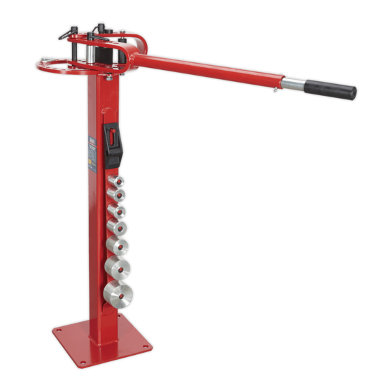
For light workshop use this compact metal bender comes in bench or floor mounted versions and is designed to bend flat, square or round solid
hot rolled mild steel up to the dimensions given below. The bender comes with the following accessories. A stop block, stop block support,
seven circular dies (1”,1.¼”,1.½”,1.¾”,2”,2½”), a sharp angle bend attachment, extending handle, one short hinge pin, two long hinge pins, plus
fixed and adjustable stops to aid repeat production of the same part.
BENDING CAPACITY (around a circular die) : Flat material - up to 5/16” x 2” Square or round material - up to 5/8”
BENDING CAPACITY (using the sharp angle attachment) : Use only flat mild steel 3/16” up to 2” wide or 1/4” up to 1 1/4”wide.
3.
ASSEMBLY & PREPARATION
F
WARNING! Ensure that you have read and understood Section 1 Safety Instructions before operating the bender.
p
F
WARNING! To avoid serious injury do not operate the bender unless it is securely mounted to the floor or workbench.
p
3.1.
Attach the ring/loop assembly to the floor stand or bench stand as indicated in fig.1.
3.1.1
Attach the loop end first by placing the long spacer (1) into the loop. Place a flat washer (3) over the bolt (2) and insert the bolt
through the loop and long spacer. Insert the protruding bolt into the mounting plate at the top of the stand ensuring that there is a
short spacer (6) sandwiched between the loop and the mounting plate. Secure with a lock washer (7) and a nut (8).
3.1.2
Attach the ring end to the stand in the two places indicated using the two 3/8” bolts with countersunk heads (5). Ensure that there is a
short spacer (6) inserted between the ring and the mounting plate through which each bolt passes. Place a flat washer and a lock
washer over each bolt and secure with a lock nut.
3.2
Attach the handle to the ring/loop as indicated in fig.2.
3.2.1
Insert the loop end of the handle inside the loop of the ring/loop assembly and secure it with one of the two longer hinge pins. The
hole selected on the handle loop will depend on the type of bend to be done. (See section 4)
3.3
Extend the handle to its full length. (See fig.2)
3.3.1
Remove the hair clip from the handle pin, then remove the pin from the handle. Pull the extension arm out of the handle tube and
align the hole at the end of the extension with the hole in the handle tube. Reinsert the pin and retain it by reinstalling the hairclip.
3.4
Fix the assembled unit to the floor or bench as appropriate.
3.4.1
Place the bender in the position where you intend to use it and rotate the handle fully in both directions to ensure that there will be no
obstructions during bending. The bender must be attached to a bench or floor using fixings which are strong enough to resist the
turning force exerted on them. Similarly the structure of the bench or floor surface must also be
sound and strong enough to resist the turning force exerted through the fixings.
fig.2
INSTRUCTIONS FOR:
FLOOR & BENCH MOUNTED METAL BENDERS
MODEL NOS:
! Wear safety goggles and gloves when bending parts.
! Always allow enough material to extend beyond the stop block
and forming dies when making bends to ensure that the material
does not come free allowing the handle to release suddenly.
% DO NOT bend any material other than hot rolled mild steel.
% DO NOT operate the metal bender if damaged.
% DO NOT allow untrained persons to operate the bender.
% DO NOT use the metal bender for purposes other than that
for which it is intended.
% DO NOT try to bend round stock using the sharp angle attachment.
% DO NOT modify the bender in any way or use a handle extension
other than the one provided.
% DO NOT try to bend material larger than the maximum sizes
stipulated below.
DO NOT bend round stock using the sharp angle attachment)
PBF04 & PBB04
fig.1
PBF04 & PBB04 - 1 - 161003
Advertisement

Related Manuals for Sealey PBF04


Summary of Contents for Sealey PBF04
- Page 1 PBF04 & PBB04 MODEL NOS: Thank you for purchasing a Sealey product. Manufactured to a high standard this product will, if used according to these instructions and properly maintained, give you years of trouble free performance. IMPORTANT: PLEASE READ THESE INSTRUCTIONS CAREFULLY. NOTE THE SAFE OPERATIONAL REQUIREMENTS, WARNINGS & CAUTIONS.
- Page 2 ( As a rough guide to initially determine an angle when bending around a centrally mounted die there are 16.36 degrees between the holes in the ring.) Measure the angle bent and make any necessary adjustments. PBF04 & PBB04 - 1 - 161003...
- Page 3 INFORMATION: For a copy of our latest catalogue and promotions call us on 01284 757525 and leave your full name and address, including postcode. 01284 757500 Sole UK Distributor www.sealey.co.uk Sealey Group, 9A> 01284 703534 Bury St. Edmunds, Suffolk. sales@sealey.co.uk email PBF04 & PBB04 - 1 - 161003...