Nibe SAM 40 Installer Manual
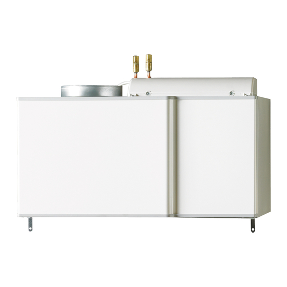
Supply air module
Hide thumbs
Also See for SAM 40:
- Installer manual (32 pages) ,
- User manual (20 pages) ,
- Installation instructions manual (12 pages)
Table of Contents
Advertisement
Quick Links
Advertisement
Table of Contents

Related Manuals for Nibe SAM 40


Summary of Contents for Nibe SAM 40
- Page 1 Installer manual SAM 40 Supply air module IHB GB 1231-2 031934...
-
Page 3: Table Of Contents
Dimensions and pipe connections 8 Accessories Symbol key 9 Technical data Outline diagram Heating medium side Dimensions and setting-out coordinates General ventilation connection Technical specifications Ventilation flow Electrical circuit diagram Adjusting ventilation Item register SAM 40 Table of Contents |... -
Page 4: Important Information
Marking SAM 40 is CE marked and fulfils IP21. The CE marking means that NIBE ensures that the product meets all regulations that are placed on it based on relev- ant EU directives. The CE mark is obligatory for most products sold in the EU, regardless where they are made. - Page 5 Setting ventilation flow supply air Heating medium (page 11) System flushed Accessories bled Check against output and pressure drop diagrams Connected according to outline diagram Electricity (page 15) Supply connected 230 V Connected communication SAM 40 Chapter 1 | Important information...
- Page 6 AIT France, Parc d'activités économique "Les Couturiers",16 rue des couturières, 67240 Bischwiller Tel : 03 88 06 24 10 Fax : 03 88 06 24 11 E-mail: info@nibe.fr www.nibe.fr NIBE Energy Systems Ltd, 3C Broom Business Park, Bridge Way, Chesterfield S41 9QG Tel: 0845 095 1200 Fax: 0845 095 1201 E-mail: info@nibe.co.uk www.nibe.co.uk...
-
Page 7: Delivery And Handling
Installation area Leave a space of 500 mm in front of the supply air mod- ule. All service on SAM 40 can be carried out from the front. NOTE Ensure that there is sufficient space (300 mm) above the supply air module for installing ventil- ation hoses. -
Page 8: The Design Of The Supply Air Module
3 The design of the supply air module Chapter 3 | The design of the supply air module SAM 40... - Page 9 Supply air module Electrical components Accessory card SAM 40 AA5-S2 Dip switch AA100 Joint card Pipe connections Switch, position 0 - 1, main switch XL33 Ventilation connection supply air, Ø 160 mm W101 Cord with connection plug XL34 Ventilation connection outdoor air, Ø 160 mm...
-
Page 10: Pipe And Ventilation Connections
4 Pipe and ventilation connections General pipe connections Dimensions and pipe connec- tions Pipe installation must be carried out in accordance with current norms and directives. Ø22 Chapter 4 | Pipe and ventilation connections SAM 40... -
Page 11: Symbol Key
UKV (CP1), according to outline diagram above. NOTE If several climate systems (ECS 40/ECS 41) are present, SAM 40 must be connected in parallel with climate system 1. SAM 40 Chapter 4 | Pipe and ventilation connections... - Page 12 2. Connect heating medium and ventilation pipes. 2. Remove the top panel on VPB 200 (installed with 6 screws). 3. Install SAM 40 from the top and slide into position. 4. Secure SAM 40 with the 2 supplied screws. 5. Connect heating medium and ventilation pipes.
-
Page 13: Heating Medium Side
Heating medium side A water borne climate system with a volume of at least 20 litres must be present for installation of SAM 40 to be possible. For correct function of SAM 40 the total volume of the climate system (excluding the internal volume in F750) must exceed 40 litres. - Page 14 75 l/h DUT -30 ºC 4000 3800 75 l/h DUT -20 ºC 3600 3400 3200 75 l/h DUT -10 ºC 3000 2800 2600 2400 2200 2000 1800 Luftflöde 1600 (m3/h) (l/s) Chapter 4 | Pipe and ventilation connections SAM 40...
- Page 15 Flöde (l/h) 1000 The diagram shows pressure drop across SAM 40 during different water flows. Note that the pressure drop is the same as that which affects the climate system 1. Check that the working point is inside the grey working area.
-
Page 16: General Ventilation Connection
B. installation efficiency and thus poorer operating economy, and may result in moisture damage to the house. (Pa) 90/100% Ø160 Luftflöd (m3/h) (l/s) Effekt 90/100% Luftflöde (m3/h) (l/s) Chapter 4 | Pipe and ventilation connections SAM 40... -
Page 17: Electrical Connections
This section describes the electrical connection for con- trolling SAM 40 from NIBE F750. The heat pump switch must be in the ” ” and SAM 40's switch in 0position before commencing work. 1. Ensure that the products are completely disconnected from the power source. -
Page 18: Commissioning And Adjusting
2. Fill with water using the filler valve (QM11) in F750. 3. Vent the heating medium system with the vent valves (QM20) above SAM 40, and the vent valves in F750 and fill if necessary using the filler valve (QM11) in F750. -
Page 19: Start-Up And Inspection
Read what menu in the control system this page of the start guide is based on. The digits in brackets refer to the 1. Set switch (SF1) on SAM 40 in position "1". menu number in the control system. 2. Turn the heat pump's switch (SF1) to " ". - Page 20 At outdoor temperatures that lie between the stated points in the diagram below, the supply air temperature can be calculated linearly. The angle of the graph contin- ues outside the stated points. (ºC) (ºC) Chapter 6 | Commissioning and adjusting SAM 40...
-
Page 21: Disturbances In Comfort
Manage alarm Start by checking the following possible fault sources: That the heat pump is running or that the supply cable to SAM 40 is connected. Group and main fuses of the accommodation. The property's earth circuit breaker. The heat pump's miniature circuit breaker (FA1). - Page 22 Vent the heating medium system via its vent valve(QM20). High supply air temperature Incorrect value set in supply air automatic control system. Enter menu 5.3.9 (ext sup air md) and adjust the setting for the supply air temperature. Chapter 7 | Disturbances in comfort SAM 40...
-
Page 23: Accessories
8 Accessories Brackets Wall mounting of SAM 40. Part no. 067 083 Buffer vessel UKV UKV 40 Part no. 088 470 Top cabinet Top cabinet for concealing the ventilation ducts. 245 mm Part no. 089 756 345 mm Part no. 089 757 395-645 mm Part no. -
Page 24: Technical Data
9 Technical data Dimensions and setting-out coordinates Ø22 Ø160 Chapter 9 | Technical data SAM 40... -
Page 25: Technical Specifications
Part No. 067 147 The value varies with the selected fan curve. Visit www.nibe.eu for more extensive sound data including sound to channels. The value can vary with the room's damping capacity. These values apply with a damping of 4 dB. -
Page 26: Electrical Circuit Diagram
Electrical circuit diagram Chapter 9 | Technical data SAM 40... -
Page 27: Item Register
Preparations, 16 Removing the covers, 5 Safety information, 2 Contact information, 4 Inspection of the installation, 3 Marking, 2 Serial number, 2 Symbols, 2 Serial number, 2 Start-up and inspection, 17 Symbol key, 9 SAM 40 Chapter 10 | Item register... - Page 28 Chapter 10 | SAM 40...
- Page 29 SAM 40 Chapter 10 |...
- Page 30 Chapter 10 | SAM 40...
- Page 32 NIBE AB Sweden Hannabadsvägen 5 Box 14 SE-285 21 Markaryd info@nibe.se www.nibe.eu 031934...
Need help?
Do you have a question about the SAM 40 and is the answer not in the manual?
Questions and answers