Nibe SAM 40 Installer Manual
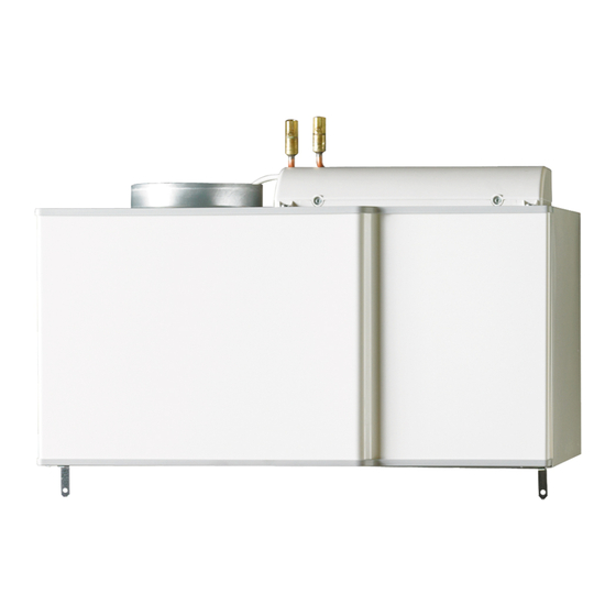
Supply air module
Hide thumbs
Also See for SAM 40:
- Installer manual (32 pages) ,
- User manual (20 pages) ,
- Installation instructions manual (12 pages)
Table of Contents
Advertisement
Quick Links
Advertisement
Table of Contents

Related Manuals for Nibe SAM 40


Summary of Contents for Nibe SAM 40
- Page 1 Installer manual SAM 40 Supply air module IHB EN 1846-1 531368...
-
Page 3: Table Of Contents
Adjusting ventilation Dimension and ventilation connections 5 Electrical connections General Connections 6 Commissioning and adjusting Preparations Filling and venting Start-up and inspection 7 Program settings Menu system 8 Disturbances in comfort Info-menu Troubleshooting 9 Accessories SAM 40 Table of Contents |... -
Page 4: Important Information 4 10 Technical Data
The serial number can be found at the bottom left inside the front cover. NOTE If the supply cable is damaged, only NIBE, its service representative or similar authorised person may re- place it to prevent any danger and damage. - Page 5 Setting ventilation flow supply air Heating medium (page 10) System flushed Accessories bled Check against output and pressure drop diagrams Connected according to outline diagram Electricity (page 16) Supply connected 230 V Connected communication SAM 40 Chapter 1 | Important information...
-
Page 6: Delivery And Handling
Installation area Leave a free space of 800 mm in front of the supply air module. All service on SAM 40 can be carried out from the front. NOTE Ensure that there is sufficient space (300 mm) above the supply air module for installing ventilation hoses. -
Page 7: The Design Of The Supply Air Module
3 The design of the supply air module BT22 XL33 QM20 XL34 BT23 PF 1 HQ11 AA100 AA5-S2 XL33 QM20 XL34 QN40 BT69 BT68 HQ11 Svenskt produktblad XL37 EP13 XL36 W102 W101 QN40 SAM 40 Chapter 3 | The design of the supply air module... -
Page 8: Pipe Connections
Temperature sensor, outdoor air Rating plate BT68 Temperature sensor, flow Not visible in the image BT69 Temperature sensor, return Designations in component locations according to standard IEC 81346-1 and 81346-2. Chapter 3 | The design of the supply air module SAM 40... -
Page 9: Pipe And Ventilation Connections General Pipe Connections
Compatible NIBE heat pumps SAM 40 is installed in a cold climate. SAM 40 is installed together with a compatible exhaust air heat pump from NIBE. You adjust the settings and SAM 40 read off sensor values etc. -
Page 10: Dimensions And Pipe Connections
2. Work from the current supply air flow. 3. Work from the desired supply air temperature, then calculate the output that SAM 40 must give at DOT. 4. Determine the water flow across SAM 40 from the correct output diagram. - Page 11 200 l/h 200 l/h 4600 4000 4200 3600 3800 3200 3400 75 l/h 2800 3000 2400 75 l/h 2600 2000 2200 1600 1800 1200 1400 Tilluftsflöde Tilluftsflöde Tilluftsflöde Tilluftsflöde (l/s) (l/s) SAM 40 Chapter 4 | Pipe and ventilation connections...
- Page 12 Supply temperature 55°C, DUT -20°C Flöde Effekt Effekt The diagram shows the climate system’s required pres- (watt) sure drop. The pressure drop across SAM 40 is the same 6400 as that across the climate system that is parallel with 6000 SAM 40. 5600...
-
Page 13: Installation Alternative
4. Install SAM 40 from the top and slide into position. Installation alternative SAM 40 can be installed in several different ways, some of which are shown below. More information about the options is available at nibe.eu. Mounting Installing on brackets 1. - Page 14 If there are closed tem, for example. thermostat valves blocking the flow through the radiat- SAM 40 is connected in parallel with the extra climate ors/underfloor heating coils, the volume in these cannot system. be included in the system volume.
-
Page 15: General Ventilation Connection
■ hood/grille, bear in mind that the two air flows must not short circuit to prevent the extract air from being drawn into SAM 40 again. ■ When external devices that affect the ventilation are used, for example kitchen fans and stoves, the heat pump must be in operation. -
Page 16: Electrical Connections
Connecting to compatible heat pump The heat pump switch must be moved to position " " and the switch (SF1) on SAM 40 to position 0, before any work can be started. 1. Ensure that the products are completely disconnec- Connection of external frost protection ted from the power source. -
Page 17: Commissioning And Adjusting
Filling the climate system Fill with water using the filler valve in the heat pump. Venting the climate system 1. Vent SAM 40 through the vent valve (QM20) and the other climate systems through their respective vent valves. 2. Keep topping up and venting until all air has been removed and the pressure is correct. -
Page 18: Start-Up And Inspection
Even if ventilation is roughly set at installation it is import- mate system" on page 17 for information about venting. ant that a ventilation adjustment is ordered and permit- ted. NOTE Order a ventilation adjustment to complete the setting. Chapter 6 | Commissioning and adjusting SAM 40... -
Page 19: Program Settings
°C Caution This accessory may require a program software update in your heat pump. The heat pump software must be version 8432R2 (F370)/3585R2 (F750) or later. SAM 40 Chapter 7 | Program settings... -
Page 20: Disturbances In Comfort
That the heat pump is running or that the supply cable ■ ing the source of the fault. to SAM 40 is connected. Group and main fuses of the accommodation. ■ Low pressure alarm The property's earth circuit breaker. - Page 21 Low supply air temperature Air in the heating medium system. ■ Vent SAM 40 using vent valve (QM20). – Incorrect value set in supply air automatic control sys- ■ tem. Enter menu 5.3.9 (ext sup air md) and reduce the –...
-
Page 22: Accessories
9 Accessories Bracket BAU 10 Wall mounting of SAM 40. Part no. 067 526 Buffer vessel UKV UKV 40 Part no. 088 470 Top cabinet Top cabinet that conceals the ventilation ducts. Height 245 mm Height 345 mm Part no. 067 517 Part no. - Page 23 10 Technical data Dimensions and setting-out coordinates Ø22 Ø160 SAM 40 Chapter 10 | Technical data...
- Page 24 Part No. 067 147 The value varies with the selected fan curve. For more detailed sound data including sound to channels visit nibe.eu. The value may vary with the room’s damping capacity. These values apply with 4 dB of damping.
-
Page 25: Electrical Circuit Diagram
Electrical circuit diagram SAM 40 Chapter 10 | Technical data... - Page 26 Heating medium side, 10 Preparations, 17 Removing the covers, 6 Safety information, 4 Inspection of the installation, 5 Marking, 4 Symbols on SAM 40, 4 Serial number, 4 Start-up and inspection, 18 Setting the ventilation, 18 Symbols, 4 Symbols on SAM 40, 4...
- Page 27 Tel: +7 831 419 57 06 E-mail: kuzmin@evan.ru www.nibe-evan.ru NIBE AB Sweden, Box 14, Hannabadsvägen 5, SE-285 21 Markaryd Tel: +46 (0)433 73 000 E-mail: info@nibe.se www.nibe.se For countries not mention in this list, please contact Nibe Sweden or check www.nibe.eu for more information.
- Page 28 WS name: Anna SAM WS version: a2 (working edition) Publish date: 2018-11-21 08:36 NIBE AB Sweden Hannabadsvägen 5 Box 14 SE-285 21 Markaryd info@nibe.se www.nibe.eu 531368...
Need help?
Do you have a question about the SAM 40 and is the answer not in the manual?
Questions and answers