Table of Contents
Advertisement
Quick Links
Advertisement
Table of Contents

Related Manuals for Datalogic Laser Sentinel


Summary of Contents for Datalogic Laser Sentinel
- Page 1 Laser Sentinel INSTRUCTION MANUAL Safety Laser Scanner...
- Page 2 Electronic versions of this document may be downloaded from the Datalogic website (www.datalogic.com). If you visit our website and would like to make comments or suggestions about this or other Datalogic pub- lications, please let us know via the "Contact" page.
-
Page 3: End User License Agreement
Products; (iv) rent or transfer all or some of the Software to any other party without Datalogic’s prior written consent. 1.3. Title to the licensed Software shall be and remain with Datalogic or the third party from whom Datalogic has obtained a license right. This Agreement does not grant to End User any intellectual property rights. - Page 4 (additional) license fees due and any further damages, if any. 2. License Fee License fees shall be due by End User to Datalogic according to the terms provided for in the relevant contract for the purchase of the Datalogic Product.
- Page 5 Technical Data and Computer Software clause at DFARS 252.227-7013(c)(1)(ii), which- ever is applicable. 8.2 If End User is using the Datalogic Product outside of the United States, End User must comply with the applicable local laws of the country in which the Datalogic Prod- uct is used and with U.S.
- Page 6 11. General Provisions. 11.1. Entire Agreement; Amendment. This document contains the entire agreement between the parties relating to use of the Datalogic Products and the licensing of the Software and supersedes all prior or contemporaneous agreements, written or oral, between the parties concerning the use of the Datalogic Products and licensing of the Software.
- Page 7 Any dispute arising out of or in connection with this contract, including any question regarding its existence, validity or termination, shall be referred to and finally resolved by arbitration administered by the Singapore International Arbitration Centre (“SIAC”) in accordance with the Arbitration Rules of the Singapore International Arbitration Cen- tre ("SIAC Rules") for the time being in force, which rules are deemed to be incorpo- rated by reference in this clause.
-
Page 8: Table Of Contents
Reseller Technical Support ....................... xii GENERAL VIEW.......................XIII Laser Sentinel Master Model ..................xiii Laser Sentinel Slave Model .................... xiv Laser Sentinel Stand Alone Model ................... xv LEDs and Indicators ....................... xvi Model Selection and Order Information ................xvii Connectors used ......................xvii GENERAL INFORMATION .................... - Page 9 Memory Group Unmounting for Cable Connection ............35 Safety Information Regarding Mounting ................37 ELECTRICAL CONNECTIONS ..................38 Laser Sentinel Stand Alone Model Connectors ..............38 Machine Interface Connections ......................39 Master Slave System Connection ..................40 Master Connection ......................41 Master M12 8-Pole Connector ......................41...
- Page 10 Fast Replacement of the Master device ..................115 Fast Replacement of a Slave device ....................116 TECHNICAL DATA ....................117 OVERALL DIMENSIONS ..................122 Laser Sentinel Stand Alone Model ................. 122 Laser Sentinel Master Model ..................123 Laser Sentinel Slave Model ................... 123 ACCESSORIES ......................124 Mounting Brackets .......................
-
Page 11: Preface
WARNING TECHNICAL SUPPORT Support Through the Website Datalogic provides several services as well as technical support through its website. Log on to ( www.datalogic.com For quick access, from the home page click on the search icon , and type in the name of the product you’re looking for. -
Page 12: Reseller Technical Support
PREFACE Reseller Technical Support An excellent source for technical assistance and information is an authorized Datalogic reseller. A reseller is acquainted with specific types of businesses, application software, and computer systems and can provide individualized assistance. SAFERY LASER SCANNER... -
Page 13: General View
GENERAL VIEW LASER SENTINEL MASTER MODEL 1. Ethernet Input Connector 4.-5. I/O Connectors (8+12 poles or 17+8 (configuration PC or host) poles, according to model) 2. Direct Mounting Holes (2) 6. Ethernet Output Connector (to Slaves) 3. Bracket Mounting Holes (4) 7. -
Page 14: Laser Sentinel Slave Model
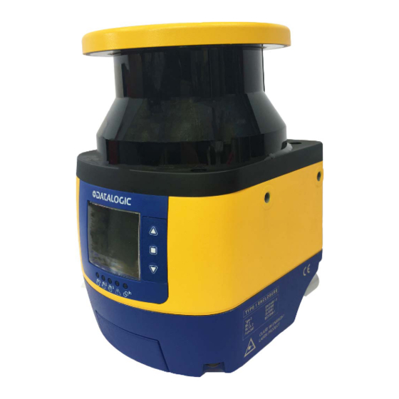
GENERAL VIEW LASER SENTINEL SLAVE MODEL 1. Laser scanner window 5. Ethernet Input Connector 2. Display 6. Ethernet Output Connector 3. LED Indicators 7. Device Class and Warning Labels 4. Keypad 8. Direct Mounting Holes (2) Figure 2 - Slave model... -
Page 15: Laser Sentinel Stand Alone Model
LASER SENTINEL STAND ALONE MODEL LASER SENTINEL STAND ALONE MODEL 1. Laser scanner window 5. Keypad 2. Display 6. I/O Connector (8 poles) 3. LED Indicators 7. Device Class and Warning Labels 4. Ethernet Connector 8. Direct Mounting Holes (2) -
Page 16: Leds And Indicators
GENERAL VIEW LEDS AND INDICATORS Figure 4 - Laser Sentinel LEDs and Indicators SYMBOL DEFINITION COLOR MEANING OUTPUT STATUS LED 1: Object No object detected in Green OSSDs ON Detection in Safety Zone 1 Safety Zone 1 Object detected in... -
Page 17: Model Selection And Order Information
MODEL SELECTION AND ORDER INFORMATION MODEL SELECTION AND ORDER INFORMATION MODEL DESCRIPTION CODE SLS-SA5-08 Stand Alone 5.5 m 6 zone sets Enhanced 958001090 SLS-SA3-08 Stand Alone 3 m 6 zone sets Enhanced 958001080 SLS-M5-0812 Master 5.5 m 10 zone sets 958001040 SLS-M5-0812-E Master 5.5 m 10 zone sets Enhanced... - Page 18 GENERAL VIEW xviii SAFERY LASER SCANNER...
-
Page 19: General Information
CHAPTER 1 GENERAL INFORMATION GENERAL DESCRIPTION The Laser Sentinel is an electro-sensitive protective equipment (ESPE). It employs active opto-electronic protective devices responsive to the diffuse reflection of a radiation (AOPDDRs), according to the definition and requirements of international safety stan- dard IEC 61496-3. -
Page 20: Reference Standards And Regulations
GENERAL INFORMATION REFERENCE STANDARDS AND REGULATIONS The safety laser scanner is a safety system used as an accident-prevention protection device and is manufactured in accordance with the international Standards in force for safety, in particular: STANDARD DESCRIPTION Harmonisation of the laws of the Member States 2014/30/EU EMC Directive relating to electromagnetic compatibility. -
Page 21: Package Contents
As the required knowledge may not be completely included in this manual, we suggest contacting Datalogic Technical Service for any further information relative to the func- tioning of the safety laser scanner and the safety rules that regulate the correct installa-... -
Page 22: Typical Applications
This area cannot be used for safety pur- poses. The possible applications to employ the Laser Sentinel are: Horizontal (to monitor an area that must be crossed in order to reach the hazardous point) and Vertical (to moni- tor an access point). -
Page 23: Horizontal Application Configuration
The device uses a horizontal protective field (the red area in the figures) to detect the presence of an object or a person. The Laser Sentinel will scan the environment surrounding the hazardous point to detect approaching objects or people. If someone is detected in the safety zone (with a given detection capability), a stopping signal is sent to the machine by the device. -
Page 24: Vertical Application Configuration
TYPICAL APPLICATIONS VERTICAL APPLICATION CONFIGURATION Figure 3 - Vertical application The device uses a vertical protective field (the red area in the figure) to detect someone passing through it. In this example the only way to reach the hazardous point is to pass through an open- ing: all other access points to the machine are protected by some physical barrier or other sensors. -
Page 25: Applications With Master And Slave Connection
The Laser Sentinel can effectively solve this situation: irrespective of the use in horizon- tal or vertical position, up to 4 Laser Sentinel units can be easily connected to each other through Ethernet-based safe communication bus, working as a single system. -
Page 26: Safety Information
(e.g. motor power supplies, inverters, etc.). • Do not connect any of the Laser Sentinel inputs to DC power sources outside of the declared range or to any AC power source, to avoid the risk of electric shock. SAFERY LASER SCANNER... - Page 27 • Every access to the configuration tools must be allowed only to restricted and highly qualified personnel. The configuration upload through the GUI is only allowed by password. • Periodically monitor the optical window during the entire product life-cycle check- ing for any damage, scratches or dirt spots.
-
Page 28: Installation
• The safety laser scanner must be mounted securely and must not be able to be moved. • Make sure that the Laser Sentinel output window is not obstructed by any object. SAFERY LASER SCANNER... -
Page 29: Getting Started
GETTING STARTED Here are the basic steps to start a safety configuration. • Package Contents: Check that the Laser Sentinel and all parts supplied with the equipment are present and intact when opening the packaging (refer to " Package Contents" on page 3 •... -
Page 30: Light Interference
INSTALLATION Light Interference Reflecting surfaces located near the safety device may cause passive reflections. These can affect the detection of an object inside the safety zone. The passive light sources can be an incandescent lamp, sunlight, a fluorescent light, a strobe light or other infra- red light sources (e.g. -
Page 31: High Reflecting Background
If there is a high reflecting background within 3 meters of the safety zone boundary, e.g. a metallic glossy surface, the Laser Sentinel might fail to recognize the exact distance of the detected object because of an increase in the measure error. -
Page 32: Zone With Limited Detection Capability
INSTALLATION ZONE WITH LIMITED DETECTION CAPABILITY Laser Sentinel may not properly detect an object located at a distance of 10 cm or less from the safety zone origin. This zone is called “zone with limited detection capability.” In this circumstance, a risk assessment is recommended taking into account the possi- bility that an object can cross a zone with limited detection capability. -
Page 33: Device Positioning And Minimum Distance Calculations
DEVICE POSITIONING AND MINIMUM DISTANCE CALCULATIONS The Laser Sentinel must be carefully positioned to fulfill its safety function. In fact, access to the dangerous area must only be possible by passing through the safety zone. Under standard operating conditions, starting the machine must not be possible while operators are inside the safety area. -
Page 34: Minimum Safety Distance Calculations For Horizontal Applications
INSTALLATION Minimum Safety Distance Calculations for Horizontal Applications The Minimum Safety Distance cannot exceed the nominal maximum limit of the Safety Zone for the scanner (5.5 m). NOTE If the device is mounted with a detection angle of less than 30° with respect to the hori- zontal plane (floor), the application is considered horizontal (parallel approach). - Page 35 Example of additional distance due to Height: With a given machine stopping time of 0.4 s and a selected Laser Sentinel Response Time of 62 ms, detection capability = 70 mm and without any ambient interference: S = [(1600 mm/s*(0.062 s+0.4 s)] + [(1200 mm –...
- Page 36 INSTALLATION Example of additional distance due to Ambient Interference: From the previous example with a height of 300 mm, but in the presence of high reflec- tive backgrounds and/or direct bright light: Minimum safety distance S - C = [(1600 mm/s*(0.062 s + 0.4 s)] + (1080 mm + 100 mm) = 1919.2 AMBIENT INTERF = 200 mm for “dust filter level”...
-
Page 37: Minimum Safety Distance Calculations For Vertical Applications
K = 1600 mm/s or 2000 mm/s (see Note) T = t C = 8(d -14 mm) or 850 mm (see Note) = Response time of the Laser Sentinel (s) (see " Response Time and Scan Cycle Setting" on page 62... - Page 38 100 mm. Figure 7 - Access protection shows the use of Laser Sentinel as a whole-body safety device where the refer- Figure 7 ence boundary is the edge of the safeguarded aperture. In this application we have to...
-
Page 39: Unprotected Zone
UNPROTECTED ZONE UNPROTECTED ZONE The unprotected zone (a) must be small enough to ensure that a person cannot approach the danger zone or stay between the danger zone and the safety zone without being detected. This can require additional mechanical protection. Figure 8 - Safety Distance Example (Top View) Figure 9 - Safety Distance Example (Side View) INSTRUCTION MANUAL... -
Page 40: Distance To Wall
INSTALLATION DISTANCE TO WALL The Safety Zone must maintain a tolerance of at least 40 mm from any wall or fixed object (a and b in the image above). This value is generally enough to guarantee normal operation, however accord- NOTE ing to the real reflectance characteristics of the wall, a higher value may be necessary. -
Page 41: Devices Orientation
Specific mounting requirements must be followed to prevent a dangerous failure. • Tilt the Laser Sentinel so that the scanning plane does not enter the output win- dow of any other scanner. Figure 10 - Scanner mounted ad different scanning angles •... - Page 42 INSTALLATION • Install a shielding plate to block scanning signal interference. Figure 12 - Shielding plate between scanners • Make the safety area smaller. SAFERY LASER SCANNER...
-
Page 43: Checks After First Installation
To test the detection capability of the device(s), the user can use a suitable test piece, e.g. an optically dark, opaque cylinder. The effective diameter should match the configured resolution. Datalogic suggests adopting the following procedure: Place the test piece on several points at the edges of the safety area. The safety laser scanner must detect the test piece at each position and go to STOP. - Page 44 Test the device by triggering the safety function, e.g. the machine builder can observe the reaction of the OSSDs. • For all device applications: check if the Laser Sentinel shows the interruption of the safety field using the LEDs and/or the display. •...
-
Page 45: Mechanical Mounting
CHAPTER 5 MECHANICAL MOUNTING For mechanical mounting, the Laser Sentinel has two different procedures depending on the operation necessities. The two mounting possibilities are: • direct mounting, OR • angle adjustment bracket mounting (if the pitch and the roll angles need to be adjusted). -
Page 46: Direct Mounting
MECHANICAL MOUNTING DIRECT MOUNTING The device has two M5 threaded holes on the back and four M5 threaded holes on the side. For direct mounting, use both M5 threaded holes in the back or all four M5 threaded holes on the two sides, considering the following values: •... -
Page 47: Protection Bracket Mounting (Sls-Bracket-C) (Optional)
Fasten the Protection Bracket (1) on the back of the Laser Sentinel, by using two M5 screws (2) (Maximum 2.9-3.1 Nm Torque). -
Page 48: Angle Adjustment Bracket Mounting
MECHANICAL MOUNTING ANGLE ADJUSTMENT BRACKET MOUNTING First, provide two M5 holes with 73 mm spacing on the intended wall or mounting sur- face. The M5 UNI 5933 screws used for mounting the brackets to a wall are not supplied in the SLS bracket mounting kits; they must be supplied by the user. -
Page 49: Pitch Angle Adjustment Bracket (Sls-Bracket-B)
ANGLE ADJUSTMENT BRACKET MOUNTING Pitch Angle Adjustment Bracket (SLS-BRACKET-B) Mount the pitch adjustment bracket (3) to the wall or panel by inserting two M5 UNI 5933 screws (not included), and tighten them, repeatedly alternating between one and the other, until they are completely tight. Figure 5 - Pitch Angle Adjustment Bracket INSTRUCTION MANUAL... -
Page 50: Scanner Mounting And Pitch Angle Adjustment
MECHANICAL MOUNTING SCANNER MOUNTING AND PITCH ANGLE ADJUSTMENT Make sure to use the specific Torques indicated for the different proce- dures to avoid damaging the device permanently. CAUTION The pitch angle adjustment is a procedure related to both SLS-BRACKET-A and SLS-BRACKET-B. NOTE The Positioning Memory Bracket (one piece) (8) saves the inclination angle set for the installation. - Page 51 SCANNER MOUNTING AND PITCH ANGLE ADJUSTMENT Figure 7 - Scanner Mounting and Pitch Angle Adjustment To place a device with a specific pitch angle: • Screw without tightening the M5 Scanner Fastening Screws (7), the M5 Pitch Adjusting Screws (6) and the Positioning Memory Bracket (8) with the M4 screw (9).
-
Page 52: Roll Angle Adjustment
MECHANICAL MOUNTING ROLL ANGLE ADJUSTMENT The roll angle adjustment is a procedure related only to SLS-BRACKET-A. NOTE Rotate the brackets to reach the desired roll angle within the allowed range (+/-8.5 °) and then tighten the M4 Roll Adjusting Screws (5) (1.4 - 1.5 N/m Torque). Figure 8 - Roll Angle Adjustment SAFERY LASER SCANNER... -
Page 53: Memory Group Unmounting For Cable Connection
MEMORY GROUP UNMOUNTING FOR CABLE CONNECTION MEMORY GROUP UNMOUNTING FOR CABLE CONNECTION Follow the Master model’s memory group unmounting procedure to connect the M12 8/12/17-pole connector (according to model) for machine interface. Adjustable torque driver with 2.5 mm hex key. NOTE 1. - Page 54 MECHANICAL MOUNTING The memory group is tightened to the scanner with captive screws, so the operator only needs to loosen them to extract it from the scanner. NOTE 4. Connect the power M12 8/12/17-pole connector (according to model). 5. Insert the memory group and tighten the two M3 fixing screws (Torque 1 N/m). 6.
-
Page 55: Safety Information Regarding Mounting
SAFETY INFORMATION REGARDING MOUNTING SAFETY INFORMATION REGARDING MOUNTING Make sure that the protection level assured by the Laser Sentinel is compatible with the danger level of the working machine, according to EN ISO 13849-1 or EN 62061. For further information refer to Chapter 4, Installation . -
Page 56: Electrical Connections
CHAPTER 6 ELECTRICAL CONNECTIONS LASER SENTINEL STAND ALONE MODEL CONNECTORS The Laser Sentinel Stand Alone model includes: M12 4-pole connector (Programming and monitoring of safety laser scanner with Graphic User Interface) M12 8-pole connector (Machine interface: power supply and inputs/outputs) -
Page 57: Machine Interface Connections
LASER SENTINEL STAND ALONE MODEL CONNECTORS Machine Interface Connections The Laser Sentinel Stand Alone model has one OSSD pair and three signals programma- ble as inputs and outputs. These signals allow the user to configure the device with sev- eral functions: •... -
Page 58: Master Slave System Connection
ELECTRICAL CONNECTIONS MASTER SLAVE SYSTEM CONNECTION The Laser Sentinel series includes various models that differ in some features, such as electrical configuration and connection type. There are two main safety laser scanner models: the Master (that can be used individu- ally or to run other slave devices) and the Slave (that must be connected to a Master and has only a particular connection to be connected to its Ethernet network). -
Page 59: Master Connection
Through the GUI, the user can choose the type of configuration. The operator must fol- low the indications for the type of pin selected and the safety standards. Input and output connected to the Laser Sentinel must be aligned with the features of the used pin. -
Page 60: Master M12 12-Pole Connector
ELECTRICAL CONNECTIONS Master M12 12-Pole Connector The M12 12-pole Master model has various pin typologies. The features of all the elec- trical pins are showed in the chart below. Figure 3 - Connector (M12, 12-pole Male) CATEGORY TYPE COLOR DESCRIPTION PIN OUT POWER SUPPLY BROWN... - Page 61 MASTER CONNECTION Make sure that the signals are aligned with the pin features and their spe- cific function. In addition, they must be correctly connected to the external device. NOTE Multi Out (8-pole and 12-pole models) The Multi Out are output signals, configurable depending on the safety application needed.
-
Page 62: Master M12 17-Pole Connector
ELECTRICAL CONNECTIONS Master M12 17-Pole Connector The M12 17-pole Master model has various pin typologies. The features of all the elec- trical pins are showed in the chart below. Figure 4 - Connector (M12, 17-pole Male) CATEGORY TYPE COLOR DESCRIPTION PIN OUT POWER SUPPLY BROWN... -
Page 63: Master M12 17+8 Pole Connector
MASTER CONNECTION Master M12 17+8 Pole Connector The M12 17-pole connector can be associated to the M12 8-pole connector for addi- tional functions, e.g. encoders. The features of all the electrical pins of the additional 8-pole connector are showed in the chart below. - Page 64 ELECTRICAL CONNECTIONS Multi In (17 pole and 17+8 pole models) The Multi In are input signals configurable depending on the safety application needed. These input signals can have the following functions: TYPE FUNCTION DESCRIPTION CONNECTION Enables the Shut Off function for energy SHUT OFF saving EDM 1...
- Page 65 MASTER CONNECTION Multi In Speed (17+8 pole models) The Multi In Speed are input signals configurable depending on the safety application needed. If the application uses encoders, all encoder inputs are employed (ENCODER 11, ENCODER 12, ENCODER 21, ENCODER 22). TYPE FUNCTION DESCRIPTION...
- Page 66 ELECTRICAL CONNECTIONS Multi In/Out (17 pole and 17+8 pole models) The Multi In/Out are signals that can be configured both as inputs and outputs. Laser Sentinel allows the operator to connect from one to three OSSD pairs; it is possible to assign to the same electrical pin input and output signals defined as Multi In or Multi Out.
-
Page 67: Laser Sentinel: The Slave
LASER SENTINEL: THE SLAVE LASER SENTINEL: THE SLAVE To create the Laser Sentinel network, the operator has to connect the Slave devices. These are equipped with rotatable side connectors for the input and output connection and will receive data and power supply from the previous devices which in turn will send it to the others. -
Page 68: Master Slave Connection
ELECTRICAL CONNECTIONS MASTER SLAVE CONNECTION Connection cables are listed in " and " Ethernet Cables" on page 125 Electrical Cables" on page 125 Do not reverse the connections: it may cause malfunctions! CAUTION A label on the rotating connector helps the user identify the right connec- tion. -
Page 69: Power Supply Connections
POWER SUPPLY CONNECTIONS POWER SUPPLY CONNECTIONS All power connections to the Laser Sentinel must strictly comply with standard regula- tions. The device requires a supply voltage of 24 Vdc. Power must be supplied in accor- dance with SELV/PELV (IEC 60204-1) for all the devices electrically connected to the safety laser scanner. -
Page 70: Laser Sentinel Setup And Configuration
LASER SENTINEL SETUP AND CONFIGURATION This chapter is dedicated to the Laser Sentinel setup and configuration using the DLSen- tinel software. The aim of this chapter is to guide the user through all the fundamental procedures of configuring the device. -
Page 71: Program Installation
When the installation is complete, the DLSentinel entry is created in the Start > All Pro- grams menu under “Datalogic” along with a desktop icon. Double-click the desktop icon to run it. A dedicated computer running DLSentinel must be connected to a Safety Laser Scanner through the Ethernet port to perform the configuration and monitoring features. -
Page 72: Functions
Laser Sentinel and no input signals are needed to manage it. Laser Sentinel allows the user to set up a given number of Zone Sets: a maximum of six Zone Sets for the Stand Alone model, a maximum of three Zone Sets for the 8-pole Mas- ter model, a maximum of ten Zone Sets for the 12-pole Master model, and a maximum of seventy Zone Sets for the 17+8 pole Master model. -
Page 73: Zone Set Switching
ZONE SETTING CONFIGURATION AND SELECTION • Define the input combinations. • Make sure that the system, which generates the input combination, can dynami- cally switch the state of the inputs within the required time and without passing through intermediate invalid combination states. It is possible to insert a delay up to 100 ms for the input switching (INPUT DELAY) to guarantee the correct timing during the Area Switching. - Page 74 NOTE 3. Assign each Area Switch to an available Input Signal Pin. The Stand Alone Laser Sentinel has three configurable Inputs. If the user chooses to employ from three to six Zone Sets there will be no available I/ O for other functions. For example, it will not be possible to employ the NOTE Manual Restart or send an electrical warning signal.
- Page 75 ZONE SETTING CONFIGURATION AND SELECTION The following figure shows the possible input combinations in case of six Zone Sets. Figure 3 - Six Zone Sets (Stand Alone model) M12 12-pole Master model: 10 Zone Sets The M12 12-pole Master model can monitor up to 10 different areas. To do that, the user must configure the input combination by selecting the signal “Area Switch”, set five inputs as Area Switch and then create a sequence of univocal combinations as described above.
- Page 76 FUNCTIONS M12 17+8 pole Master model: 70 Zone Sets The M12 17+8 pole Master model can monitor up to 70 different areas. To do that: 1. Set the Zone Set No. to “70”. 70 Zone Sets will appear with their relative Area Switch combinations.
-
Page 77: Detection Capability Setting
The detection capability is the ability to detect an object of given dimensions within the detection zone. In particular, for the Laser Sentinel, the test piece taken as reference is an opaque cylinder with at least 300mm height and the diameter equal to the detection capability measured in millimeters. -
Page 78: Automatic And Manual Restart
FUNCTIONS AUTOMATIC AND MANUAL RESTART If Laser Sentinel detects an opaque object, the OSSD outputs switch to the OFF-status (the opening of the safety contacts). The restart mode allows the safety laser scanner to return to a normal operating condition. - Page 79 AUTOMATIC AND MANUAL RESTART The Manual Restart input must be connected to a 24 Vdc normally open contact. NOTE If an object is not removed from the Safety zone and the operator attempts to restart the device, by pressing the button for more than 500 ms, the Safety Laser Scanner remains in Interlock OFF status.
-
Page 80: Response Time And Scan Cycle Setting
The response time of the Laser Sentinel is the time from when an object enters the safety zone to when the OSSD goes to the OFF-status due to the detection of the object. The Laser Sentinel scans cyclically with a constant speed and it employs 30 ms to do one complete rotation. -
Page 81: Reference Points Monitoring Settings
Example application for movable structure protection When the reference points (minimum 3), are set on the position of a movable structure, such as a door, the OSSD goes to the OFF-state if the Laser Sentinel detects a change in the position of the door. - Page 82 GUI gives a warning message indicating that this configuration is not valid for whole body protection applications (greater than 1.6 m/s). To safely apply the Laser Sentinel in applications with normal approach (i.e. when the monitored plane is vertical), refer to IEC 61496-3 Annex A.12.
-
Page 83: Safety Outputs (Ossds)
SAFETY OUTPUTS (OSSDS) SAFETY OUTPUTS (OSSDs) The OSSD (Output Signal Switching Device) is a safety output for safety-related parts of a machine control system. When the device detects an object or a person in the Safety zone, the OSSD goes to the OFF-status (the machine stops). The device generates signals to monitor the OSSD status and these periodically force the OSSD into a temporary OFF condition if the OSSD is ON (when there is no object detected in the Safety zone). -
Page 84: Ossd Test
FUNCTIONS OSSD 1/1 must be paired with OSSD 1/2. OSSD 2/1 must be paired with OSSD 2/2. OSSD 3/1 must be paired with OSSD 3/2. NOTE OSSD test The following diagram illustrates the different times needed for OSSD tests. Figure 13 - OSSD test Where: s T1 (Test pulse width) = 115... -
Page 85: Muting
MUTING MUTING The Muting feature allows the automatic deactivation of the safety status on the whole (Total Muting) or part (Partial Muting) of the safety area. This feature is particularly suit- able when an object, but not a person, has to pass through the dangerous area. This allows carrying out definite cyclical operations without blocking a working machine. -
Page 86: Muting Enable
FUNCTIONS Muting Enable When the Muting feature is implemented (through two Muting inputs), a third input can be used to dynamically control whether Muting will be performed or not. The third input is labeled MUTING ENABLE and works as follows: prior to a valid Muting sequence on the Muting inputs, if the MUTING ENABLE signal is at a high level, the Muting feature is enabled, and Muting will be performed;... - Page 87 MUTING The sensors A1/A2 are connected to Muting 1 input and the sensors B1/B2 are con- nected to Muting 2 input. The user has to mount the sensors A1/A2 or B1/B2 at a “D” distance. “D” depends on the package length (L): D < L; “d1” is the maximum dis- tance between the Muting sensors (this distance depends on the package speed (V): d1max[cm] = V[m/s] * T12[s] * 100);...
-
Page 88: Unidirectional Muting
FUNCTIONS Unidirectional Muting In Unidirectional type operation, the device enters in Muting if the Muting 2 input goes high after the rising of Muting 1 (or vice versa). The user can set the value of Max Mut- ing Inputs Delay between Muting 1 and Muting 2 from a minimum of 1 sec to a maxi- mum of 16 sec. -
Page 89: Configuring The Muting Function On Dlsentinel
MUTING Configuring the Muting Function on DLSentinel To enable the Muting function on DLSentinel and configure the Muting area, follow the procedure below: 1. On the Output Configuration page, set the Muting item to ENABLED. 2. On the Input Configuration page, assign the Muting signals to the available pins. INSTRUCTION MANUAL... - Page 90 FUNCTIONS 3. On the Zones Configuration page, first draw your Safety Area, then click on the Muting 1 label in the panel on the left side. A warning message is displayed informing the user that any change to the Safety Area will remove the Muting zone.
- Page 91 MUTING 5. If a Total Muting zone was created, the Muting zone (colored blue) will overlap the Safety Area, as illustrated in the picture below. A Total Muting zone can be turned into a Partial Muting zone by dragging and dropping the points of the shape.
-
Page 92: Override
Muting Dependent Override in Stand Alone Model The Override feature is possible when the Laser Sentinel is in the SAFE state (detection in the Safety Zone) and allows the user to force the OSSDs to ON state whenever it is necessary to restart the machine. - Page 93 OVERRIDE Single input line pattern The input sequence to be followed for activation is indicated in the figure below: Level triggered pattern The input sequence to be followed for activation is indicated in the figure below: Edge triggered pattern The input sequence to be followed for activation is indicated in the figure below: The Level and the Edge triggered patterns can be enabled with the M12 12 or 17-pole Master connector only.
-
Page 94: Edm
FUNCTIONS The External Device Monitoring (EDM) function controls external devices by verifying the OSSDs status. EDM enabled When EDM is enabled it is necessary to connect the EDM input to a 24 VDC normally- closed contact of the device to be monitored. The figures below show how to connect the EDM input. - Page 95 The function controls the 24VDC normally-closed contact switching according to the changes of the OSSDs status. Figure 17 - EDM timings The EDM status is antivalent with OSSDs: the timing diagram explains the relationship between the cause (OSSDs) and the effect (EDM) with the maximum permissible delay. DLSentinel makes it possible to adjust the maximum permissible delay between 200 and 1000 ms.
-
Page 96: Encoders
FUNCTIONS ENCODERS In dynamic applications, the safety area can change according to the position, direction, and speed of the vehicle. A typical example is the use of the Safety Laser Scanner on an Automated Guided Vehicle (AGV). If the speed changes, the minimum safety distance changes accordingly (the faster the movement, the longer the distance). - Page 97 ENCODERS To configure the necessary zone sets for a dynamic application, enable the encoder function in the Zone Set configuration page on DLSentinel. Input Delay Max [msec] This parameter is valid when there are at least two Zone Sets. It determines the delay to apply between switching from one Zone Set to the next.
- Page 98 FUNCTIONS • If the vehicle speed is in the range between -30 cm/s and -10 cm/s or +10 cm/s and +30 cm/s, the Encoder Δ can be exceeded for max. 60 s. • If the vehicle speed is in the range ≤ -30 cm/s or ≥ +30 cm/s, the Encoder Δ can be exceeded for max.
- Page 99 ENCODERS In the example above, the EncR value is 10,000 / 125.66 = 79.58 p/cm. Therefore, on DLSentinel the rounded value “80” must be entered in the relevant Encoder [p/cm] field. The software will calculate the max. allowed speed based on this data. After setting the encoder values, the Zone Sets must be configured.
- Page 100 FUNCTIONS Encoder 2 ratio = 60 p/cm 2 = 100,000 / 60 = 1,667 cm/s 2 = - 100,000 / 60 = - 1,667 cm/s Therefore, the maximum and minimum speeds that the Safety Laser Scanner can read equal respectively 1,667 cm/s and -1,667 cm/s. The Speed Ranges of each Zone Set can- not exceed these values.
-
Page 101: Dust Filtering
A High Dust Filter Level is used in dirty environments to filter (ignore) detection of air- borne particles from being confused with objects to detect. The Laser Sentinel is less sensitive to dust and therefore avoids shutting down the machinery unnecessarily. -
Page 102: Shut Off
FUNCTIONS SHUT OFF The Shut Off function allows energy saving, which can be particularly useful when the Safety Laser Scanner is used in battery-powered applications (e.g. AGV). When the Safety Laser Scanner is in Shut Off status, some of its functions are deacti- vated, but the device is still active and ready to restore to normal operation when needed. -
Page 103: Reset
RESET RESET Reset is a function that allows restoring normal operation after a failure lockout condi- tion, due to system error, without disconnecting the power supply. The aim of the Reset is to return the system to a power-on phase, by resetting all the variables and starting a new integrity test session. -
Page 104: Wink
FUNCTIONS WINK Wink is a function that allows recognizing which device is to be configured from those available on the Network. The Wink function can be activated through the discovery by clicking on the wink but- ton, and then the Wink icon will be displayed. Figure 20 - GUI Wink button Figure 21 - Wink displayed icon SAFERY LASER SCANNER... -
Page 105: Safety Report Generation And Acceptance
SAFETY REPORT GENERATION AND ACCEPTANCE SAFETY REPORT GENERATION AND ACCEPTANCE The Safety Report is a file that sums up all the parameters selected for a configuration and is generated by the GUI after creating a configuration. The Report file is displayed on the right side of the panel. It is possible to save it as a PDF file and print it. -
Page 106: Diagnostics
CHAPTER 9 DIAGNOSTICS MONITORING BY DISPLAY DISPLAYED ICON NAME DESCRIPTION Configuration Configuration valid pending acceptance The device is correctly func- tioning (OSSDs GO Condi- ON State tion). No presence detected in the Safety and Warning Area. The device is correctly func- Warning for tioning. -
Page 107: Diagnostic Notes, Warnings, And Errors
Invalid boot. Re-boot the system until the normal condition is BOOTF NORMAL restored. If warning persists, con- tact Datalogic Technical Support. Muting has expired because it is MUT TIMEOUT NORMAL maintained beyond the maximum timeout time. Muting has not activated because... - Page 108 DIAGNOSTICS DISPLAYED DISPLAYED DEVICE OSSD DESCRIPTION ICON FAULT CODE STATUS STATUS OVERRIDE NORMAL The Override function is active The external temperature is above OVERTEMP NORMAL the limit. The Override timeout function has OVR TIMEOUT NORMAL expired. A high reflecting background is detected that could have an impact on detection capability.
- Page 109 Check network connector or the integrity of Slave devices and INFT20 NORMAL restore normal network operation. If failure persists, contact Datalogic Technical Support. The input received from Encoder 1 or Encoder 2 exceeds the maximum pulse frequency. ENC OUT OF FREQ...
- Page 110 DIAGNOSTICS DISPLAYED DISPLAYED DEVICE OSSD DESCRIPTION ICON FAULT CODE STATUS STATUS This error can occur if one of the following conditions is met: •The difference between the speed measures collected by Encoder 1 ENC ERROR LOCKOUT and Encoder 2 exceeds the Encoder Δ...
- Page 111 DIAGNOSTIC NOTES, WARNINGS, AND ERRORS DISPLAYED DISPLAYED DEVICE OSSD DESCRIPTION ICON FAULT CODE STATUS STATUS Fast replacement backup phase in BKP IN PROGRESS BOOT progress. Wait and do not push any button. Fast replacement backup phase BKP DONE BOOT completed. Fast replacement backup phase BKP FAILED BOOT...
-
Page 112: Safety
Except for the procedures described in this document, the device components must not be opened. If you cannot remedy the fault with the help of the information provided in this chapter, please contact Datalogic Technical Service. NOTE SAFERY LASER SCANNER... -
Page 113: Leds And Display
LEDS AND DISPLAY LEDs AND DISPLAY The safety laser scanner is equipped with three lateral buttons, a graphical display and four status LEDs located below the display. Diagnostic and Status LEDs The safety laser scanner has diagnostic LEDs for initial diagnostics. The OFF state and ON state LEDs can be found below the safety laser scanner display. -
Page 114: Display Menu
DIAGNOSTICS Display Menu To enter the Display Menu, push the squared button. By using the up and down arrows button, it is possible to browse the menu. To select an area, press the squared button. To exit every menu option, push the squared button after selecting it. The menu is divided into three main areas: Information, Settings and Exit: INFORMATION Device Name... -
Page 115: Diagnostic Log
DIAGNOSTIC LOG DIAGNOSTIC LOG Several categories of events (regarding the Master and the Slave devices) are logged into a specific file saved both in the Memory Group and the Master device. To view the events occurred to your device(s), launch DLSentinel, discover your device or cluster, then go to Scanner >... - Page 116 DIAGNOSTICS Once the log file creation is completed, the following information window is displayed: You can now view your log file. Figure 1 - Log file example The following categories of logged events are included: • Output events (intrusions into safety areas) •...
-
Page 117: Periodical Checks
If any of these checks are not verified, it is not allowed to continue to work on the machine. In this case the installation of the laser Sentinel must be checked by qualified safety personnel and tested following the “CHECKS AFTER FIRST INSTALLATION” proce- dure as indicated. -
Page 118: Device Maintenance
DEVICE MAINTENANCE GENERAL INFORMATION AND USEFUL DATA The Laser Sentinel does not include any repairable components; avoid repairing or replacing device parts not mentioned in this manual. Failing to observe this instruction may cause malfunction due to severe device damage. -
Page 119: Window Cleaning
WINDOW CLEANING WINDOW CLEANING The Laser Sentinel optical window needs periodical cleaning, and the frequency depends on the type of environment in which the device operates. Contamination of the optical window (due to dust, oil, etc.) in the presence of background reflection may impair the detection capability of the safety laser scanner. - Page 120 DEVICE MAINTENANCE It is necessary to clean the underside of the end cap (the black surface under the yellow cap on top of the scanner). NOTE SAFERY LASER SCANNER...
-
Page 121: Window Replacement
Order the replacement window from Datalogic and carefully follow the procedure below. In all other cases, please contact Datalogic for device repair or replacement. Warning Terms - Disclaimer for Window Replacement and Calibration PLEASE READ CAREFULLY THIS STATEMENT. BY REPLACING AND CALI- BRATING THE WINDOW, YOU ACKNOWLEDGE AND ACCEPT THE FOLLOWING WARNING TERMS. -
Page 122: Prerequisites For Window Replacement
THE POTENTIAL RISKS AND LIABILITIES ARISING FROM THE WINDOW REPLACEMENT PROCEDURE, AS WELL AS FROM FAILURE TO COMPLY WITH THE INSTRUCTIONS PRO- VIDED BY DATALOGIC IN THIS RESPECT. TO THE FULLEST EXTENT PERMITTED BY LAW, DATALOGIC (AND ITS DIRECTORS, OFFICERS, AFFILIATES) SHALL NOT BE HELD LIABLE FOR... -
Page 123: Window Replacement Procedure
WINDOW REPLACEMENT Window Replacement Procedure After establishing that the replacement of the optical window is necessary and after making sure that all above-mentioned prerequisites are met, start the window replace- ment procedure. The new optical window package contains the following parts: •... - Page 124 DEVICE MAINTENANCE 3. Remove the optical window with a linear, vertical movement. Take the utmost care to avoid touching or damaging the internal parts of the device. CAUTION 4. Remove the seal positioned on the device body. Avoid touching or damaging the internal parts of the device.
- Page 125 WINDOW REPLACEMENT 5. Position the new seal, gently pressing it on the device body and making sure it perfectly adheres to it. Before closing the window, take sufficient measure to prevent dust and any polluting agent from enter- CAUTION ing the device, as this could affect the detection capability of the Safety Laser Scanner.
-
Page 126: New Window Calibration
DEVICE MAINTENANCE New Window Calibration A 2-meter free area around the 275° angle range of the Laser Scanner is necessary to calibrate and validate the new optical window. Keep this area free for the whole duration of the procedure. NOTE If the Window Replacement procedure is performed on a Slave device, this must be connected to a Master device. - Page 127 WINDOW REPLACEMENT 13. Select the device undergoing window replacement and enter the serial number of the new window. 14. Window calibration will start now. Make sure that the device has a 2-meter free area around its 275° angle range. When window calibration is in progress, the device first switches to offline status (black display), then to offline test mode, displaying the following message.
- Page 128 DEVICE MAINTENANCE 15. If the test area is not compliant, an error message will be displayed. Clear the required area and retry. SAFERY LASER SCANNER...
- Page 129 WINDOW REPLACEMENT 16. To validate the calibration procedure, the user must test the device detection capability with a test configuration. The test area is automatically configured. To test the detection capability of the device(s), use a suitable test piece, e.g. an optically dark, opaque cylinder, with a diameter of 40 mm.
- Page 130 Should the calibration fail again, replace the window or NOTE contact Datalogic to repair or replace the device. If the Window Replacement procedure is performed on a Master device, the last configuration saved on it is preserved. If the procedure is performed on a Slave device, this must be connected to a Master device.
- Page 131 WINDOW REPLACEMENT 17. After window calibration has successfully completed, the following fault message is displayed. Click OK. The device display will show the “Commit On Field” warning message. 18. Restore the Safety Laser Scanner on field. See Chapter 4, Installation Chapter 5, , and .
-
Page 132: Fast Replacement
Fast replacement allows the user to quickly replace a Master or Slave device or a Mem- ory Group when these have suffered irreparable damage (see Chapter 9, Diagnostics The user is recommended to contact Datalogic Technical Support before performing Fast Replacement to assess the severity of the damage. NOTE This procedure must be performed by authorized personnel only. -
Page 133: Fast Replacement Of The Master Device
FAST REPLACEMENT Fast Replacement of the Master device When the Master device must be replaced and the Memory Group is already config- ured, follow the procedure below: 1. unmount the Memory Group from the damaged Master device and connect it to the new one (see "... -
Page 134: Fast Replacement Of A Slave Device
DEVICE MAINTENANCE Fast Replacement of a Slave device The Fast Replacement of a Slave device can occur only when a damaged Slave device is replaced with a new Slave device of the same model, and therefore only the serial num- bers do not match. -
Page 135: Technical Data
APPENDIX A TECHNICAL DATA PHYSICAL CHARACTERISTICS Protection class III (EN 61140 / IEC 61140) Supply voltage (Uv) 24 Vdc (19.2 V … 30 Vdc) (SELV/PELV) Residual ripple ± 5% Start-up current (1) < 0.6 A To meet the requirements of the relevant product standards (e.g. EN 61496-1), the external voltage sup- ply for the devices (SELV) must be able to bridge a brief mains failure of 20 ms. - Page 136 TECHNICAL DATA OSSD (SAFETY OUTPUT) OSSD logic and protection PUSH-PULL, Overcurrent protection Output voltage for ON status (HIGH) ≥ Uv-2V @ 250 mA Output voltage for OFF status (LOW) ≤ 0.2V Output current for ON status (HIGH) max. 250 mA Leakage current <...
- Page 137 MECHANICAL DATA Dimensions (W × H × D) 112.5 x 152 x 102 Weight (including system plug) 1.5 kg Housing material Aluminum Alloy Housing color YellowRAL1003 Optics cover material Optics cover surface Acrylic ENVIRONMENTAL DATA Max 95% non-condensing According to Humidity IEC 61496-1 5.4.2 IEC 61496-3 5.4.2;...
- Page 138 TECHNICAL DATA FEATURES 5.5 m Models 3 m Models 0.05 … 5.5 m for 70/150 mm of detection capability 0.05 … 3 m for 40/50/70/150 mm of detection capability 0.05 … 4 m for 50 mm of detection capability Safety protective zone range 0.05 …...
- Page 139 LIGHT BEAM DIAMETER At front screen 8 mm At middle field distance 10 mm At max distance 20 mm Detectable remission 1.8% - “1000%” Maximum homogeneous contamination of the optics cover without preventing the detection - 30% of nominal optic power capability SAFETY DATA Type...
-
Page 140: Overall Dimensions
APPENDIX B OVERALL DIMENSIONS LASER SENTINEL STAND ALONE MODEL SAFERY LASER SCANNER... -
Page 141: Laser Sentinel Master Model
LASER SENTINEL MASTER MODEL LASER SENTINEL MASTER MODEL LASER SENTINEL SLAVE MODEL INSTRUCTION MANUAL... -
Page 142: Accessories
APPENDIX C ACCESSORIES MOUNTING BRACKETS MODEL DESCRIPTION CODE SLS-BRACKET-A Complete bracket system 95ASE2920 SLS-BRACKET-B Pitch regulation bracket system 95ASE2930 SLS-BRACKET-C Head protective bracket 95ASE2940 Figure 1 - Kit A Figure 2 - Kit B Figure 3 - Kit C SAFERY LASER SCANNER... -
Page 143: Ethernet Cables
ETHERNET CABLES ETHERNET CABLES MODEL DESCRIPTION CODE CAB-ETH-M01 M12-IP67 ETHERNET Ethernet cable to Host 1 m 93A051346 CAB. (1M) CAB-ETH-M03 M12-IP67 ETHERNET Ethernet cable to Host 3 m 93A051347 CAB. (3M) CAB-ETH-M05 M12-IP67 ETHERNET Ethernet cable to Host 5 m 93A051348 CAB. -
Page 144: Safety Units
ACCESSORIES SAFETY UNITS MODEL DESCRIPTION CODE SE-SR2 Safety Unit 95ACC6170 CSME-03VU24-Y14 Forcibly guided relay interface 95ASE1270 The CSME interface requires the activation and correct wiring of an EDM signal on the Safety Laser Scanner. NOTE MAINTENANCE ACCESSORIES MODEL DESCRIPTION CODE SLS-WINDOW Replacement window 95ASE2971... -
Page 145: Glossary
APPENDIX D GLOSSARY NAME DESCRIPTION Active opto-electronic A device whose sensing function is performed by optoelectronic protective device emitting and receiving elements. These detect the diffuse reflec- responsive to diffuse tion of optical radiations generated within the device by an reflection (AOPDDR) object located in a detection zone (specified in two dimensions). - Page 146 A High Dust Filter Level is used in dirty environments to filter (ignore) detection of airborne particles from being confused with objects to detect. The Laser Sentinel is less sensitive to Dust Filtering dust and therefore avoids shutting down the machinery unnec- essarily.
- Page 147 This number depends on the parameter set in the configuration. State in which the output circuit is interrupted and does not per- mit the flow of current. When Laser Sentinel detects an object in OFF-state the safety zone it switches to this state which causes the dan- gerous machinery to stop working.
- Page 148 This is the area around the Safety Zone; the device can signal a Warning Zone warning lamp or siren if it detects an object in this area. This is an area (zone) that is controlled by the Laser Sentinel. Zone Set More than one zone can be defined and therefore switched (set) by a combination of inputs.
- Page 152 © 2018-2019 Datalogic S.p.A. and /or its affiliates • All rights reserved • Without limiting the rights under copyright, no part of this documentation may be repro- duced, stored in or introduced into a retrieval system, or transmitted in any form or by any means, or for any purpose, without the express written permission of Data- logic S.p.A.
Need help?
Do you have a question about the Laser Sentinel and is the answer not in the manual?
Questions and answers