Table of Contents
Advertisement
Advertisement
Table of Contents

Related Manuals for Datalogic Magellan 3450VSi


Summary of Contents for Datalogic Magellan 3450VSi
- Page 1 Magellan™ 3450VSi Omni-Directional Imaging Scanner Product Reference Guide...
- Page 2 Datalogic representative. Electronic versions may either be downloadable from the Datalogic website (www.datalogic.com) or provided on appropriate media. If you visit our website and would like to make comments or suggestions about this or other Datalogic pub- lications, please let us know via the "Contact Datalogic" page.
-
Page 3: Table Of Contents
Table of Contents Chapter 1. GETTING STARTED...................................1 About This Manual .....................................1 Manual Conventions ..................................1 Connecting the Scanner ..................................2 Mount Installation ....................................4 Wall Mount ....................................5 Countertop Mount ..................................5 Adjustable Riser ..................................5 Chapter 2. PROGRAMMING..................................7 Introduction to Label Programming ..............................7 Understanding the Basics .................................7 Using the Programming Bar Codes ............................7 Resetting the Standard Product Defaults ..........................8 Using a Bar Code Mask ................................9... - Page 4 Set Single Cable RS-232 STX Character ........................82 Single Cable RS-232 Use ETX ..............................83 Set Single Cable RS-232 ETX Character ........................83 Single Cable RS-232 Datalogic Extensions ........................... 84 Single Cable RS-232 Pacesetter Plus ............................ 85 USB-OEM Interface Features ................................. 86 USB OEM Scanner Device Type ..............................
- Page 5 USB Keyboard Caps Lock State ...............................91 No Keyboard Support ................................92 USB Keyboard Send Control Characters ..........................93 Quiet Interval .....................................94 USB Keyboard Intercharacter Delay ............................95 DATA EDITING....................................... 97 Data Editing Overview ..................................98 Please Keep In Mind................................98 Global Prefix/Suffix ..................................99 Global Prefix ....................................99 Global Suffix ...................................
- Page 6 EAN-8 Minimum Segment Length ............................141 EAN-8 Decoding Levels ................................. 143 Other UPC/EAN Options ................................144 In-Store Printed Label Minimum Read ..........................145 UPC/EAN Correlation ................................146 UPC/EAN Guard Insertion ..............................147 UPC/EAN Stitch Exact Label Halves ............................ 148 UPC/EAN Stitch Unlike Label Halves ..........................149 UPC/EAN Minimum Segment Length ..........................
- Page 7 Code 32 Start Stop Character Transmission ........................196 Code 32 Check Character Transmission ..........................197 Code 128 ......................................198 Code 128 Enable ..................................198 Code 128 Transmit Function Characters ..........................199 Expand Code128 to Code 39 ..............................200 Code 128 Minimum Read ..............................201 Code 128 Correlation ................................
- Page 8 MSI Length 2 ..................................245 MSI Stitching ..................................246 Standard 2 of 5 ....................................247 Standard 2 of 5 Enable ................................247 Standard 2 of 5 Check Character Calculation ........................248 Standard 2 of 5 Check Character Transmission ......................... 249 Standard 2 of 5 Minimum Read ............................
- Page 9 From microSD Card to Scanner ............................329 Application code load to scanner ..........................329 Configuration load to scanner ............................. 329 Appendix I. HANDHELD DATA FORMAT REQUIREMENTS ....................... 331 Handheld Data Format Requirements General ......................... 331 Datalogic Handheld Data Format Requirements ....................... 332 Product Reference Guide...
- Page 10 GS1 DataBar Omnidirectional ............................332 GS1 DataBar Expanded ..............................332 UPC-A ..................................... 332 UPC-A with 2-Digit Supplemental ..........................332 UPC-A with 5-Digit Supplemental ..........................332 UPC-E ..................................... 332 UPC-E with 2-Digit Supplemental ..........................332 UPC-E with 5-Digit Supplemental ..........................333 EAN-8 .....................................
-
Page 11: Chapter 1 Getting Started
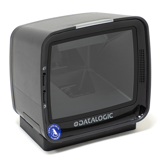
Chapter 1 Getting Started The Magellan™ 3450VSi On-Counter Vertical Presentation Scanner is designed for small counter retail checkout environments where there is a relatively high number of transactions with a fairly small number of items per transaction. The scanner has a reduced footprint, allowing more room for item merchandising of high margin impulse items clustered around the POS (Point of Sale). -
Page 12: Connecting The Scanner
Connecting the Scanner Connecting the Scanner The scanner kit you ordered to match your interface should provide a compati- ble cable for your installation. Alternatively, if your scanner receives Power Off the Terminal (POT) it might be possible to connect using a cable from a previ- ously existing installation (except for USB). - Page 13 Manual Conventions Connect the scanner to a USB port on the terminal/PC using USB Connection — the correct USB cable for the interface type you ordered. Reference Figure 1 on page USB installations may require a power connection via an approved A/C Adapter as shown in Figure 1 .
-
Page 14: Mount Installation
Mount Installation Figure 4. Scanner Features - Bottom View USB Aux Port USB Micro-B MicroSD Card Power Host Port EAS Wire Cavity Mount Installation Options for mounting the scanner to a wall or countertop include an L-Bracket or an adjustable riser. Figure 5 shows the scanner being seated in an L-Bracket. -
Page 15: Wall Mount
Wall Mount Wall Mount Attach the L-Bracket to the wall, securing it in the desired position with two screws through the two holes in the back face of the L-Bracket as shown in Fig- 5. It is recommended to use two pan head (8.2mm or 5/16” maximum head diameter) #8 screw with a thread profile that suits the mounting surface mate- rial in the wall. - Page 16 Mount Installation NOTES Magellan™ 3450VSi...
-
Page 17: Chapter 2 Programming
Chapter 2 Programming Introduction to Label Programming The programming bar code labels contained in this manual will allow you to customize and configure features and settings for your scanner. To ensure full compatibility and proper function, use only the programming bar codes in this manual and other product-specific publications to program scanner features. -
Page 18: Resetting The Standard Product Defaults
Understanding the Basics Resetting the Standard Product Defaults If you are unsure of what programming options are in your scanner, or you’ve Stan- changed some options and want the factory settings restored, scan the dard Product Default Settings bar code below. This will copy the factory config- uration for the currently active interface to the current configuration. -
Page 19: Using A Bar Code Mask
Using a Bar Code Mask Using a Bar Code Mask The programming bar codes in this manual have been placed as multiples per page. In order to present them only one at a time to the scanner, a bar code mask is provided on the opposite side of this page. -
Page 20: Bar Code Mask
Bar Code Mask Bar Code Mask Cut a hole in this page and remove it from the manual as indicated to create a sleeve through which bar codes (starting in the following section) can be indi- vidually viewed and scanned. It is important that only one bar code at a time be presented to the scanner. -
Page 21: General Scanner Features
General Scanner Features starting on page 12 CANNING EATURES 1D Double Read Timeout on page 12 • 2D Double Read Timeout on page 13 • Digital Watermark (DWM) Features on page 14 • Digital Watermark (DWM) Enable on page 14 Digital Watermark (DWM) Double Read Timeout on page 15 Digital Watermark (DWM) Data Format on page 16 Sleep Mode Timer on page 17... -
Page 22: Double Read Timeout
Enter/Exit Programming Mode 1D Double Read Timeout SCANNING FEATURES 1D Double Read Timeout The 1D Double Read Timeout feature specifies the minimum allowable time which must pass before reading the same 1D label again (e.g. two identical items in succession). To set the Double Read Timeout: 1. -
Page 23: Double Read Timeout
2D Double Read Timeout Enter/Exit Programming Mode 2D Double Read Timeout The 2D Double Read Timeout feature specifies the minimum allowable time which must pass before reading the same 2D label again (e.g. two identical items in succession). To set this feature: 1. -
Page 24: Digital Watermark (Dwm) Features
Enter/Exit Programming Mode Digital Watermark (DWM) Features Digital Watermark (DWM) Features Digital Watermark (DWM) Enable Enables/Disables the ability of the scanner to decode Digital Watermarks. To set this feature: 1. Scan the Enter/Exit Programming Mode bar code. 2. Scan your selection from the bar codes below. You’ll need to cover any unused bar codes on this and the facing page to ensure that the scanner reads only the bar code you intend to scan. -
Page 25: Digital Watermark (Dwm) Double Read Timeout
Digital Watermark (DWM) Features Enter/Exit Programming Mode Digital Watermark (DWM) Double Read Timeout Specifies the minimum allowable time which must pass before reading the same Digital Watermark (DWM) label again (e.g. two identical items in succes- sion). To set this feature: 1. -
Page 26: Digital Watermark (Dwm) Data Format
Enter/Exit Programming Mode Digital Watermark (DWM) Features Digital Watermark (DWM) Data Format Selects the format for the watermark data. Choices are: • Compatibility mode • Databar-14 • Native 1. Scan the Enter/Exit Programming Mode bar code. 2. Scan your selection from the bar codes below. You’ll need to cover any unused bar codes on this and the facing page to ensure that the scanner reads only the bar code you intend to scan. -
Page 27: Sleep Mode Timer
Sleep Mode Timer Enter/Exit Programming Mode Sleep Mode Timer This feature specifies the amount of time of inactivity (with no label reads) before the scanner enters sleep mode. To set this feature: 1. Scan the Enter/Exit Programming Mode bar code. 2. -
Page 28: Inverse Read Control
Enter/Exit Programming Mode 1D Inverse Read Control 1D Inverse Read Control This configuration item is used to toggle inverted label reading for 1D bar codes, for example, a label printed as white on black as opposed to black on white. To set this feature: 1. -
Page 29: Inverse Read Control
2D Inverse Read Control Enter/Exit Programming Mode 2D Inverse Read Control This configuration item is used to toggle inverted label reading for 2D bar codes, for example, a label printed as white on black as opposed to black on white. To set this feature: 1. -
Page 30: Illumination During Disable Mode
Enter/Exit Programming Mode Illumination During Disable Mode Illumination During Disable Mode This feature allows illumination to be turned off when the scanner is in “disable” mode. It determines if the imager illumination is controlled by host interface enable/disable commands. = Illumination is not controlled by host enable/disable commands, Disable illumination stays on when disabled. -
Page 31: Object Sense Control
Object Sense Control Enter/Exit Programming Mode Object Sense Control This feature determines whether the main illumination is controlled by the Object Sensing system, or alternatively, stays continuously on. = Illumination is controlled by using Object Sense Enable = Normal illumination is used but it goes off during sleep mode / Disable disable mode To set this feature:... -
Page 32: Reading Illumination Duration
Enter/Exit Programming Mode Reading Illumination Duration Reading Illumination Duration This feature specifies how long the illumination stays on after a label or label segment is read. To set this feature: 1. Scan the Enter/Exit Programming Mode bar code. 2. Scan your selection from the bar codes below. You’ll need to cover any unused bar codes on this and the facing page to ensure that the scanner reads only the bar code you intend to scan. -
Page 33: Power On Alert
Power On Alert Enter/Exit Programming Mode LED AND BEEPER INDICATORS Power On Alert Disables or enables the indication that the scanner has finished all its power up tests and is now ready for operation (usually a single beep). This feature is configurable so the beep can be replaced with a .wav file. -
Page 34: External Read Indicator (Eri) Active State High
Enter/Exit Programming Mode External Read Indicator (ERI) Active State High External Read Indicator (ERI) Active State High This feature is available only through use of a special cable. NOTE 00F900(CR) DEFAULT ERI Active State = Active Low 00F901(CR) ERI Active State = Active High Magellan™... -
Page 35: Eri Timeout
ERI Timeout Enter/Exit Programming Mode ERI Timeout Specifies the amount of time the External Read Indicator (ERI) signal is held active for a good read. Sets the ERI timeout duration using hex values from 000 to 255 in increments of ten milliseconds (10ms or 0.01 seconds). To configure this feature: 1. -
Page 36: Good Read Led Idle State
Enter/Exit Programming Mode Good Read LED Idle State Good Read LED Idle State This feature specifies the state of the green scanner LEDs when the scanner is idle and ready to read a label. Options are: • • On dim To set the Scanner LEDs Idle State: 1. -
Page 37: Scanner Control Button Options
Scanner Control Button Options Enter/Exit Programming Mode Scanner Control Button Options Configure the Scanner Control Button to one of the following modes of opera- tion: • Enable all functions: Volume, tone, diagnostics and reset. • Enable only volume, tone and reset. •... -
Page 38: Good Read Beep Control
Enter/Exit Programming Mode Good Read Beep Control Good Read Beep Control This feature enables/disables scanner beep upon successfully decoding of a label. To set this feature: 1. Scan the Enter/Exit Programming Mode bar code. 2. Scan your selection from the bar codes below. You’ll need to cover any unused bar codes on this and the facing page to ensure that the scanner reads only the bar code you intend to scan. -
Page 39: Good Read Beep Frequency
Good Read Beep Frequency Enter/Exit Programming Mode Good Read Beep Frequency Adjusts the scanner’s good read beep to sound at low, medium, or high fre- quency (controls the beeper’s pitch/tone). • • Medium • High To set this feature: 1. Scan the Enter/Exit Programming Mode bar code. 2. -
Page 40: Good Read Beep Length
Enter/Exit Programming Mode Good Read Beep Length Good Read Beep Length Specifies the duration of a good read beep. To set this feature: 1. Scan the Enter/Exit Programming Mode bar code. 2. Scan the bar code, Set Good Read Beep Length on page 30. -
Page 41: Good Read Beep Volume
Good Read Beep Volume Enter/Exit Programming Mode Good Read Beep Volume Selects the beeper volume upon a good read beep. There are five selectable volumes, with each volume increment adding approximately five decibels to the previous level: • • Medium High •... -
Page 42: Good Read When To Indicate
Enter/Exit Programming Mode Good Read When to Indicate Good Read When to Indicate This feature specifies when the scanner will provide indication (beep and/or flash its green LEDs) upon successfully reading a bar code. • Good Read = Indicate after decode. •... -
Page 43: Host Download To Handheld
Host Download to Handheld Enter/Exit Programming Mode Host Download to Handheld Attached Datalogic handheld scanners can be updated via the host port. Con- tact Technical Support for details. Handheld Host Download Timeout This feature sets the timeout (in seconds) to wait for a response from the hand- held when performing a host download to the handheld. - Page 44 Enter/Exit Programming Mode Host Download to Handheld NOTES Magellan™ 3450VSi...
-
Page 45: Imaging Features
Imaging Features starting on page 36 MAGING EATURES Image Capture to the Host by Camera Button on page 38 • Camera Button Mode on page 38 Image Destination on page 39 Cell Phone Mode on page 40 • Cell Mode Percent on page 41 •... -
Page 46: Imaging Features
Enter/Exit Programming Mode How to Capture an Image Imaging Features How to Capture an Image There are two methods of capturing images as discussed below: • Image Capture to a microSD Card by Scanning a Special Label on page 36 •... -
Page 47: Image Capture To The Host By Host Command
Imaging Features Enter/Exit Programming Mode Image Capture to the Host by Host Command This feature is only available for RS-232 and USB COM interfaces. If the USB COM interface has been selected, follow the instruc- tions in USB-COM Interface Setup on page 57 . NOTE The host command format is as follows: P<cnt>pSBC... -
Page 48: Image Capture To The Host By Camera Button
Enter/Exit Programming Mode Image Capture to the Host by Camera Button Image Capture to the Host by Camera Button Perform the following steps to set up the Camera Button. 1. Set the Camera Button Mode to enabled. 2. Set the Image Capture destination to host port. 3. -
Page 49: Image Destination
Imaging Features Enter/Exit Programming Mode Image Destination Specifies the destination for pictures/images taken with a camera button press. 042500(CR) DEFAULT Image Destination = Disable 042501\r Image Destination = SD card 042503\r Image Destination = Host port Product Reference Guide... -
Page 50: Cell Phone Mode
Enter/Exit Programming Mode Image Capture to the Host by Camera Button Cell Phone Mode Enables/disables the operating mode for mobile phone read. When cell phone mode is enabled, the scanner stays on regardless of host com- mand or button push. It will not enter sleep mode. 046701(CR) Cell Phone Mode = Disable 046702(CR) -
Page 51: Cell Mode Percent
Imaging Features Enter/Exit Programming Mode Cell Mode Percent Specifies the rate of frames dedicated to reading cell phones. Cell reading fea- ture must be enabled for this to be active. The setting reflects a variable setting (or percentage) of frames dedicated to cell reading As the percentage is increased, object sense (if enabled) will become less responsive. -
Page 52: Picture Retrieval Timeout
Enter/Exit Programming Mode Image Capture to the Host by Camera Button Picture Retrieval Timeout This feature sets the amount of time after the picture retrieval label is sent to the POS that the scanner will allow subsequent picture taking requests via but- ton press. - Page 53 Imaging Features Enter/Exit Programming Mode Picture Retrieval Timeout (continued) 042306(CR) Picture Retrieval Timeout = 6 seconds 042307(CR) Picture Retrieval Timeout = 7 seconds 042308(CR) Picture Retrieval Timeout = 8 seconds 042309(CR) Picture Retrieval Timeout = 9 seconds 04230A(CR) Picture Retrieval Timeout = 10 seconds Product Reference Guide...
-
Page 54: Image Capture Delay
Enter/Exit Programming Mode Image Capture Delay Image Capture Delay This feature specifies the amount of time after the image capture is initiated by a button press until the picture is taken. 042700(CR) Image Capture Delay = 0 seconds 042701(CR) Image Capture Delay = 1 second 042702(CR) Image Capture Delay = 2 seconds 042705(CR) -
Page 55: Image Format
Imaging Features Enter/Exit Programming Mode Image Format This feature specifies the output format for images taken using the camera function of the scanner. Choices are: • • 03E900(CR) DEFAULT Image Format = JPG 03E901(CR) Image Format = BMP Product Reference Guide... -
Page 56: Image Size
Enter/Exit Programming Mode Image Size Image Size This feature specifies the size of the captured image. Choices are: Video Graphics Array. 640 x 480 pixels. VGA — Wide Video Graphics Array, various physical sizes, 16:9 shape WVGA. Maximum image height and width. Largest image. Full Size. -
Page 57: Image Brightness
Imaging Features Enter/Exit Programming Mode Image Brightness Specifies the image brightness value. The selectable range is from 0 to 10, with 10 being the brightest. 03EB00(CR) DEFAULT Image Brightness = 0 03EB01(CR) Image Brightness = 1 03EB02(CR) Image Brightness = 2 03EB03(CR) Image Brightness = 3 03EB04(CR) - Page 58 Enter/Exit Programming Mode Image Brightness Image Brightness (continued) 03EB08(CR) Image Brightness = 8 03EB09(CR) Image Brightness = 9 03EB0A(CR) Image Brightness = 10 Magellan™ 3450VSi...
-
Page 59: Image Contrast
Imaging Features Enter/Exit Programming Mode Image Contrast This feature sets the contrast level for a captured image. The selectable range is from 0 to 10, with 0 being the lowest and 10 being the highest contrast. 03EC00(CR) DEFAULT Image Contrast = 0 03EC01(CR) Image Contrast = 1 03EC02(CR) - Page 60 Enter/Exit Programming Mode Image Contrast Image Contrast (continued) 03EC08(CR) Image Contrast = 8 03EC09(CR) Image Contrast = 9 03EC0A(CR) Image Contrast = 10 Magellan™ 3450VSi...
-
Page 61: Image Compression
Imaging Features Enter/Exit Programming Mode Image Compression Specifies the starting image compression factor. 03ED05(CR) Image Compression = 5 03ED0A(CR) Image Compression = 10 03ED19(CR) Image Compression = 25 03ED32(CR) Image Compression = 50 03ED46(CR) Image Compression = 70 03ED50(CR) Image Compression = 80 03ED5A(CR) Image Compression = 90 03ED64(CR) -
Page 62: Region Of Interest (Roi)
Enter/Exit Programming Mode Region of Interest (ROI) Region of Interest (ROI) This feature specifies the X-Y coordinates for the Region of Interest (ROI). The region of interest coordinates are defined as follows: Where xmax is the x-size of a full size image (1279 pixels), and ymax is the y-size of a full size image (1023 pixels). - Page 63 Region of Interest (ROI) Region of Interest (continued) 04EC000004FF000003FF(CR) DEFAULT Region of Interest = default 04EC0000028000000200(CR) Region of Interest = upper left quadrant 04EC028004FF00000200(CR) Region of Interest = upper right quadrant 04EC00000280020003FF(CR) Region of Interest = lower left quadrant 04EC028004FF020003FF(CR) Region of Interest = lower right quadrant Product Reference Guide...
- Page 64 Imaging Features NOTES Magellan™ 3450VSi...
-
Page 65: Interface Related Features
Set Single Cable RS-232 STX Character on page 82 Single Cable RS-232 Use ETX on page 83 • Set Single Cable RS-232 ETX Character on page 83 Single Cable RS-232 Datalogic Extensions on page 84 • Single Cable RS-232 Pacesetter Plus on page 85 •... -
Page 66: Interface Type
Interface Type starting on page 88 USB K EYBOARD EATURES Keyboard Layout on page 88 • USB Keyboard Country Mode on page 88 • USB Keyboard Caps Lock State on page 91 • No Keyboard Support on page 92 • USB Keyboard Send Control Characters on page 93 •... -
Page 67: Usb-Com Interface Setup
USB-COM Interface Setup The scanner has two USB-COM interfaces, USB-COM and USB-COM DL (Data- logic). The Datalogic USB-COM driver works for both USB-COM interfaces. Before plugging your scanner into the Host PC, please ensure you have already copied the executable DLS USB-COM driver file to your PC and that the scan- ner’s interface is set to USB COM or USB COM DL. -
Page 68: Usb Interface Selection
Enter/Exit Programming Mode USB Interface Selection USB Interface Selection Remember to cover any unused bar codes on this and the facing page to ensure that the scanner reads only the bar code you intend to scan. Great care should be taken to select the correct interface type, since you can cause damage to the scanner and/or POS termi- nal by attempting to change to an incompatible interface. -
Page 69: Keyboard Interface Selection
Interface Type Enter/Exit Programming Mode Keyboard Interface Selection Remember to cover any unused bar codes on this and the facing page to ensure that the scanner reads only the bar code you intend to scan. Great care should be taken to select the correct interface type, since you can cause damage to the scanner and/or POS terminal by attempting to change to an incompatible interface. -
Page 70: Maximum Host-Transmitted Message Length
Enter/Exit Programming Mode Maximum Host-Transmitted Message Length INTERFACE FEATURES Maximum Host-Transmitted Message Length Specifies the maximum number of data characters allowed in messages trans- mitted to the host. To set the Maximum Host-Transmitted Message Length: 1. Scan the Enter/Exit Programming Mode bar code. 2. -
Page 71: Rs-232 Interface Features
RS-232 Interface Features Enter/Exit Programming Mode RS-232 Interface Features A setting of no parity with 7 data bits is invalid and will default to 8 data bits and no parity. NOTE RS-232 Baud Rate 001D04(CR) RS-232 Baud Rate = 1200 001D03(CR) RS-232 Baud Rate = 2400 001D02(CR) - Page 72 Enter/Exit Programming Mode RS-232 Baud Rate RS-232 Baud Rate (continued) 001D07(CR) RS-232 Baud Rate = 57600 001D08(CR) RS-232 Baud Rate = 115200 001D09(CR) RS-232 Baud Rate = 230400 Magellan™ 3450VSi...
-
Page 73: Number Of Data Bits
RS-232 Interface Features Enter/Exit Programming Mode RS-232 Number of Data Bits Specifies number of data bits required for sending and receiving data. A setting of 7 data bits with no parity will default to 8 data bits and no parity. NOTE 009B00(CR) RS-232 Number of Data Bits = 7... -
Page 74: Parity
Enter/Exit Programming Mode RS-232 Parity RS-232 Parity Specifies parity required for sending and receiving data. Options for this setting are: • RS-232 PARITY = NONE • RS-232 PARITY = EVEN • RS-232 PARITY = ODD A setting of no parity with 7 data bits will default to 8 data bits and no parity. -
Page 75: Hardware Control
RS-232 Interface Features Enter/Exit Programming Mode RS-232 Hardware Control Enables/disables use of the RS-232 CTS signal for flow control and/or scan control. Options are: • Disable — The scanner transmits to the host regardless of any activity on the CTS line. •... -
Page 76: Intercharacter Delay
Enter/Exit Programming Mode RS-232 Intercharacter Delay RS-232 Intercharacter Delay Specifies delay between the end of one character and the beginning of the next in 10-millisecond increments. This delay is inserted after each data character transmitted. If the transmission speed is too high, the system may not be able to receive all characters. -
Page 77: Software Flow Control
RS-232 Interface Features Enter/Exit Programming Mode RS-232 Software Flow Control Enables/disables RS-232 Flow Control using XON/ XOFF characters. This item will be ignored when the feature, RS-232 NAK Charac- ter, is enabled NOTE To set this feature: 1. Scan the Enter/Exit Programming Mode bar code. 2. -
Page 78: Beep On Ascii Bel
Enter/Exit Programming Mode RS-232 Beep on ASCII BEL RS-232 Beep on ASCII BEL Enables/disables ability of scanner to beep (sound a good read tone) on receiv- ing an ASCII BEL (07 hex). 069D00(CR) DEFAULT RS-232 Beep on ASCII BEL = Disable 069D01(CR) RS-232 Beep on ASCII BEL = Enable Beep on Not on File... -
Page 79: Ack Nak Features
RS-232 Interface Features Enter/Exit Programming Mode RS-232 ACK NAK Features ACK NAK Enable This enables/disables the ability of the scanner to support the RS-232 ACK/ NAK protocol. When configured, the scanner and/or host sends an “ACK” when it receives data properly, and sends “NAK” when the data is in error. Selections for this option are: •... -
Page 80: Rs-232 Ack Character
Enter/Exit Programming Mode RS-232 ACK NAK Features RS-232 ACK Character This feature specifies which ASCII character will be used as an ACK character. DO NOT set this feature to use previously defined char- acters such as XON, XOFF or host commands as this will conflict with normal operation of these characters. -
Page 81: Rs-232 Nak Character
RS-232 Interface Features Enter/Exit Programming Mode RS-232 NAK Character This feature specifies which ASCII character will be used as a NAK character. DO NOT set this feature to use previously defined char- acters such as XON, XOFF or host commands as this will conflict with normal operation of these characters. -
Page 82: Rs-232 Retry On Ack Nak Timeout
Enter/Exit Programming Mode RS-232 ACK NAK Features RS-232 Retry on ACK NAK Timeout This option specifies the action scanner performs on expiration of the RS-232 ACK NAK Timeout Value. 032100(CR) RS-232 Retry on ACK NAK Timeout = Disable 032101(CR) DEFAULT RS-232 Retry on ACK NAK Timeout = Enable Magellan™... -
Page 83: Rs-232 Ack Nak Timeout Value
RS-232 Interface Features Enter/Exit Programming Mode RS-232 ACK NAK Timeout Value This item specifies the time the scanner will wait for an ACK character from the host following a label transmission. • 0 = Infinite timeout • 1 - 75 = Timeout in 200-millisecond increments To set the ACK NAK Timeout Value: 1. -
Page 84: Rs-232 Ack Nak Retry Count
Enter/Exit Programming Mode RS-232 ACK NAK Features RS-232 ACK NAK Retry Count This feature sets the number of times for the scanner to retry a label transmis- sion under a retry condition. To set the RS-232 ACK NAK Retry Count: 1. -
Page 85: Rs-232 Ack Nak Error Handling
RS-232 Interface Features Enter/Exit Programming Mode RS-232 ACK NAK Error Handling This item specifies the method the scanner will use to handle errors detected while waiting to receive the ACK character from the host. Errors include unrec- ognized host commands and communication errors such as parity or framing errors. -
Page 86: Indicate Transmission Failure
Enter/Exit Programming Mode RS-232 Indicate Transmission Failure RS-232 Indicate Transmission Failure This feature enables / disables the ability of the scanner to sound a bad label beep indication when a transmission failure occurs. To set this feature: 1. Scan the Enter/Exit Programming Mode bar code. 2. -
Page 87: Ignore Host Commands
RS-232 Interface Features Enter/Exit Programming Mode RS-232 Ignore Host Commands When set to ignore host commands, the scanner will ignore all host commands except the minimum set necessary to keep the interface active and transmit labels. For normal operation of the interface, select Obey Host Commands. 04F400(CR) DEFAULT RS-232 Ignore Host Commands = Don’t Ignore... -
Page 88: Single Cable Rs-232 Features
Enter/Exit Programming Mode Single Cable RS-232 Shared Options Single Cable RS-232 Features Single Cable RS-232 Shared Options The RS-232 Single Cable interface shares some configuration options with other RS-232 interfaces. Rather than repeat them in this section as Single Cable options, please find them referenced as follows: RS-232 Baud Rate on page 61 RS-232 Number of Data Bits on page 63... -
Page 89: Single Cable Rs-232 Rts Cts Selection
Single Cable RS-232 Features Enter/Exit Programming Mode Single Cable RS-232 RTS CTS Selection Specifies how RTS and CTS are used to control the data flow. RTS is controlled by the Scanner and can be continuously held high/low, or can be asserted during label transmission. -
Page 90: Single Cable Rs-232 Use Bcc
Enter/Exit Programming Mode Single Cable RS-232 Use BCC Single Cable RS-232 Use BCC Enables/disables the ability of the scanner to use BCC (Block Check Character). 047D00(CR) DEFAULT Single Cable RS-232 Use BCC = Disable 047D01(CR) Single Cable RS-232 Use BCC = Enable Single Cable RS-232 Use ACK/NAK Enables/disables the ability of the scanner to use ACK/NAK. -
Page 91: Single Cable Rs-232 Use Stx
Single Cable RS-232 Features Enter/Exit Programming Mode Single Cable RS-232 Use STX Enables/disables the ability of the scanner to use STX. To set this feature: 1. Scan the Enter/Exit Programming Mode bar code. 2. Scan either the enable or disable bar code below. You’ll need to cover any unused bar codes on this and the facing page to ensure that the scanner reads only the bar code you intend to scan. -
Page 92: Set Single Cable Rs-232 Stx Character
Enter/Exit Programming Mode Single Cable RS-232 Use STX Set Single Cable RS-232 STX Character This feature selects the STX character. To specify the STX Character: 1. Scan the Enter/Exit Programming Mode bar code. 2. Scan the bar code, Set Single Cable RS-232 STX Character below. -
Page 93: Single Cable Rs-232 Use Etx
Single Cable RS-232 Features Enter/Exit Programming Mode Single Cable RS-232 Use ETX Enables/disables the ability of the scanner to use ETX.. 048000(CR) Single Cable RS-232 Use ETX = Disable 048001(CR) DEFAULT Single Cable RS-232 Use ETX = Enable Set Single Cable RS-232 ETX Character Allows selection of the ETX character. -
Page 94: Single Cable Rs-232 Datalogic Extensions
Enter/Exit Programming Mode Single Cable RS-232 Datalogic Extensions Single Cable RS-232 Datalogic Extensions Enables Datalogic extensions to the interface. Contact Customer Support for more information about this feature. 050A00(CR) DEFAULT Single Cable RS-232 Datalogic Extensions = Standard Protocol 050A01(CR) Single Cable RS-232 Datalogic Extensions = Support Datalogic Extensions to Protocol Magellan™... -
Page 95: Single Cable Rs-232 Pacesetter Plus
Single Cable RS-232 Features Enter/Exit Programming Mode Single Cable RS-232 Pacesetter Plus This option enables the scanner’s ability to send Pacesetter Plus information as trailers to UPC/EAN bar codes. To set this feature: 1. Scan the Enter/Exit Programming Mode bar code. 2. -
Page 96: Usb-Oem Interface Features
Enter/Exit Programming Mode USB OEM Scanner Device Type USB-OEM Interface Features USB OEM Scanner Device Type The OEM-USB protocol allows for the scanner to be identified as one of two dif- ferent types of bar code scanners. Depending on what other scanners you may already have connected to a USB POS, you may need to change this setting to enable all scanners to communicate. -
Page 97: Usb Oem Additional Interface Options
USB-OEM Interface Features Enter/Exit Programming Mode USB OEM Additional Interface Options To set this feature: 1. Scan the Enter/Exit Programming Mode bar code. 2. Scan your selection from the bar codes below. You’ll need to cover any unused bar codes on this and the facing page to ensure that the scanner reads only the bar code you intend to scan. -
Page 98: Usb Keyboard Features
Enter/Exit Programming Mode Keyboard Layout USB Keyboard Features As a keyboard interface, the scanner supports most popular PC terminals. Keyboard Layout The Keyboard Layout option supports many countries. For details about Key- board Layout, please refer to your operating system manual. USB Keyboard Country Mode This feature specifies the country/language that will be supported by the key- board. - Page 99 USB Keyboard Features Enter/Exit Programming Mode USB Keyboard Country Mode (continued) 030206(CR) USB Keyboard Country Mode = Italy 030207(CR) USB Keyboard Country Mode = Norway 030208(CR) USB Keyboard Country Mode = Portugal 030209(CR) USB Keyboard Country Mode = Spain 03020A(CR) USB Keyboard Country Mode = Sweden 03020B(CR)
- Page 100 Enter/Exit Programming Mode USB Keyboard Country Mode USB Keyboard Country Mode (continued) 03020D(CR) USB Keyboard Country Mode = Hungary 03020E(CR) USB Keyboard Country Mode = Czech Republic 03020F(CR) USB Keyboard Country Mode = Slovakia 030210(CR) USB Keyboard Country Mode = Romania 030211(CR) USB Keyboard Country Mode =...
-
Page 101: Usb Keyboard Caps Lock State
USB Keyboard Features Enter/Exit Programming Mode USB Keyboard Caps Lock State This feature specifies the format in which the scanner sends character data. Selections are: Send character data in normal format Caps Lock OFF — Send character data in reverse case Caps Lock ON —... -
Page 102: No Keyboard Support
Enter/Exit Programming Mode No Keyboard Support No Keyboard Support Enables the scanner to perform host communications normally performed by an attached keyboard. To set this feature: 1. Scan the Enter/Exit Programming Mode bar code. 2. Scan either the enable or disable bar code below. You’ll need to cover any unused bar codes on this and the facing page to ensure that the scanner reads only the bar code you intend to scan. -
Page 103: Usb Keyboard Send Control Characters
USB Keyboard Features Enter/Exit Programming Mode USB Keyboard Send Control Characters This feature specifies how the scanner transmits ASCII control characters to the host. Affects suffix and prefix characters. When disabled, only ASCII characters between 20H and 127H inclusive (space... delete) plus special characters 0DH (carriage return), 08H (backspace), 27H (ESC), 09H (right tab) and 0BH (left tab) are transmitted. -
Page 104: Quiet Interval
Enter/Exit Programming Mode Quiet Interval Quiet Interval This setting specifies the amount of time to monitor for keyboard activity before breaking the keyboard connection. To set this feature: 1. Scan the Enter/Exit Programming Mode bar code. 2. Scan the bar code below, Set Quiet Interval. -
Page 105: Usb Keyboard Intercharacter Delay
USB Keyboard Features Enter/Exit Programming Mode USB Keyboard Intercharacter Delay Specifies a time delay between characters. To set this feature: 1. Scan the Set USB Keyboard Intercharacter Delay bar code below. 2. Scan the appropriate characters/digits from the Alpha-Numeric Keypad in Appendix C that represent the desired delay. - Page 106 Enter/Exit Programming Mode USB Keyboard Intercharacter Delay NOTES Magellan™ 3450VSi...
-
Page 107: Data Editing
Data Editing starting on page 98 DITING VERVIEW starting on page 99 LOBAL REFIX UFFIX Global Prefix on page 99 • Global Suffix on page 100 • starting on page 101 AIM ID starting on page 102 ABEL Label ID Control on page 102 •... -
Page 108: Data Editing Overview
Enter/Exit Programming Mode Data Editing Overview Data Editing Overview When a bar code is scanned, additional information can be sent to the host computer along with the bar code data. This combination of bar code data and supplementary user-defined data is called a “message string.” The features in this chapter can be used to build specific user-defined data into a message string. -
Page 109: Global Prefix/Suffix
Global Prefix Enter/Exit Programming Mode Global Prefix/Suffix Global Prefix This feature applies to RS-232 interfaces (Standard, Wincor-Nixdorf, and Single Cable). It specifies the prefix that is added to beginning of label transmission. To specify the Global Prefix Character(s): 1. Scan the Enter/Exit Programming Mode bar code. 2. -
Page 110: Global Suffix
Enter/Exit Programming Mode Global Prefix/Suffix Global Suffix This feature applies to RS-232 interfaces (Standard, Wincor-Nixdorf, and Single Cable). It specifies the suffix that is added to end of a label transmission. Three standard options are available below. Contact your dealer for other alternate settings for this feature. -
Page 111: Aim Id
Global Suffix Enter/Exit Programming Mode AIM ID AIM (Automatic Identification Manufacturers) label identifiers are assigned from a globally standardized list — as opposed to custom label ID characters you select yourself — and can be included with scanned bar code data. AIM label identifiers consist of three characters as follows: •... -
Page 112: Label Id
Enter/Exit Programming Mode Label ID Label ID Label ID Control This feature specifies whether or not Label IDs are transmitted to the host and if so, whether to attach them as a prefix or suffix. Choices are: • Disable • Enable as a Prefix •... -
Page 113: Setting Label Id
Setting Label ID Enter/Exit Programming Mode Setting Label ID This feature allows the setting of custom Label ID character(s) for each available symbology type if other than the default Label ID is desired. To set this feature: 1. Scan the Enter/Exit Programming Mode bar code. 2. -
Page 114: Symbologies
Enter/Exit Programming Mode Label ID 1D Symbologies 0024(CR) Default Label ID for this symbology is: 41 = A Set UPC-A Label ID 002D(CR) Default Label ID for this symbology is: 41 = A Set UPC-A 2-Digit Supplemental Label ID 002E(CR) Default Label ID for this symbology is: 41 = A Set UPC-A 5-Digit Supplemental Label ID... - Page 115 1D Symbologies Enter/Exit Programming Mode Setting Label ID (continued) 002F(CR) Default Label ID for this symbology is: 45 = E Set UPC-E 2-Digit Supplemental Label ID 0030(CR) Default Label ID for this symbology is: Set UPC-E 5-Digit Supplemental Label ID 45 = E 0027(CR) Default Label ID for this symbology is:...
- Page 116 Enter/Exit Programming Mode Label ID Setting Label ID (continued) 0034(CR) Default Label ID for this symbology is: Set EAN-8 5-Digit Supplemental Label ID 4646 = FF 0560(CR) Default Label ID for this symbology is: 47 = G Set GTIN Label ID 0561(CR) Default Label ID for this symbology is: Set GTIN 2-Digit Supplemental Label ID...
- Page 117 1D Symbologies Enter/Exit Programming Mode Setting Label ID (continued) 04DB(CR) Default Label ID for this symbology is: 5258 = RX DataBar Expanded Label ID 0367(CR) Default Label ID for this symbology is: DataBar Expanded Composite Label ID 5258 = RX 0365(CR) Default Label ID for this symbology is: 5258 = RX...
- Page 118 Enter/Exit Programming Mode Label ID Setting Label ID (continued) 0036(CR) Default Label ID for this symbology is: 69 = i I 2 of 5 Label ID 0037(CR) Default Label ID for this symbology is: Codabar Label ID 25 = % 0038(CR) Default Label ID for this symbology is: 26 = &...
-
Page 119: Symbologies
2D Symbologies Enter/Exit Programming Mode 2D Symbologies 0105(CR) Default Label ID for this symbology is: 446D = Dm Data Matrix Label ID 05A9(CR) PDF 417 Label ID Default Label ID for this symbology is: 50 = P 0353(CR) Default Label ID for this symbology is: Micro PDF 417 Label ID 6D50 = mP 03DC(CR) -
Page 120: Global Mid-Label Id
Enter/Exit Programming Mode Label ID Global Mid-Label ID This feature specifies a global mid-label ID that is added between two bar codes for transmission. To set this feature: 1. Scan the Enter/Exit Programming Mode bar code. 2. Scan the Set Global Mid-Label ID on page 110 bar code below. -
Page 121: Case Conversion
Global Mid-Label ID Enter/Exit Programming Mode Case Conversion This option can change the case of all alphabetic characters in scanned bar code data to upper or lower case. Case conversion affects ONLY scanned bar code data, and does not affect Label ID, Prefix, Suffix, or other appended data. -
Page 122: Character Conversion
Character Conversion Character Conversion Character conversion is an eight byte configuration item. The eight bytes are 4 character pairs represented in hexadecimal ASCII values. The first character in the pair is the character that will be converted. The second character in the pair is the character to convert to. -
Page 123: 1D Symbology Programming
1D Symbology Programming 1D Symbologies If the scanner’s interface type must be changed, always be sure that inter- face configuration is the FIRST item scanned during a programming session. (Selecting an interface type resets ALL other configuration items — includ- ing symbology programming —... -
Page 124: Coupon Control
Enter/Exit Programming Mode Coupon Control Enable Coupon Control Coupon Control Enable This feature is used to control the method of processing coupon labels. For the puposes of this feature, coupon labels are defined as: 1. UPC-A labels that start with a ‘5’ 2. -
Page 125: Coupon Label Priority Timer
Coupon Label Priority Timer Enter/Exit Programming Mode Coupon Label Priority Timer This feature sets the duration of the UPCA / DataBar coupon label priority timer. To set this feature: 1. Scan the Enter/Exit Programming Mode bar code. 2. Scan your selection from the bar codes below. You’ll need to cover any unused bar codes on this and the facing page to ensure that the scanner reads only the bar code you intend to scan. -
Page 126: Upc-A
Enter/Exit Programming Mode UPC-A Enable UPC-A UPC-A Enable Enables/disables the ability of the scanner to decode UPC-A labels. To set this feature: 1. Scan the Enter/Exit Programming Mode bar code. 2. Scan either the enable or disable bar code below. You’ll need to cover any unused bar codes on this and the facing page to ensure that the scanner reads only the bar code you intend to scan. -
Page 127: Upc-A Number System Character Transmission
UPC-A Number System Character Transmission Enter/Exit Programming Mode UPC-A Number System Character Transmission Enables/disables transmission of a UPC-A number system character. This item is ignored when the advanced feature, Full Label Edit, is enabled. NOTE To set this feature: 1. Scan the Enter/Exit Programming Mode bar code. 2. -
Page 128: Upc-A Check Character Transmission
Enter/Exit Programming Mode UPC-A Check Character Transmission UPC-A Check Character Transmission Enables/disables transmission of a UPC-A check character. This item is ignored when the advanced feature, Full Label Edit, is enabled. NOTE To set this feature: 1. Scan the Enter/Exit Programming Mode bar code. 2. -
Page 129: Upc-A Minimum Read
UPC-A Minimum Read Enter/Exit Programming Mode UPC-A Minimum Read This feature specifies the minimum number of consecutive UPC-A decodes before is accepted as good read. To set this feature: 1. Scan the ENTER/EXIT Programming Mode bar code. 2. Scan your selection from the bar codes below. You’ll need to cover any unused bar codes on this and the facing page to ensure that the scanner reads only the bar code you intend to scan. -
Page 130: Expand Upc-A To Ean-13
Enter/Exit Programming Mode Expand UPC-A to EAN-13 Expand UPC-A to EAN-13 Enables/disables expansion of UPC-A labels to EAN/JAN-13. To set this feature: 1. Scan the Enter/Exit Programming Mode bar code. 2. Scan either the enable or disable bar code below. You’ll need to cover any unused bar codes on this and the facing page to ensure that the scanner reads only the bar code you intend to scan. -
Page 131: Upc-E
UPC-E Enable Enter/Exit Programming Mode UPC-E UPC-E Enable Enables/disables the ability of the scanner to decode UPC-E labels. To set this feature: 1. Scan the Enter/Exit Programming Mode bar code. 2. Scan either the enable or disable bar code below. You’ll need to cover any unused bar codes on this and the facing page to ensure that the scanner reads only the bar code you intend to scan. -
Page 132: Upc-E Number System Character Transmission
Enter/Exit Programming Mode UPC-E Number System Character Transmission UPC-E Number System Character Transmission Enables/disables transmission of a UPC-E number system character. This item is ignored when the advanced feature, Full Label Edit, is enabled. NOTE To set this feature: 1. Scan the Enter/Exit Programming Mode bar code. 2. -
Page 133: Upc-E Check Character Transmission
UPC-E Check Character Transmission Enter/Exit Programming Mode UPC-E Check Character Transmission Enables/disables transmission of a UPC-E check character. This item is ignored when the advanced feature, Full Label Edit, is enabled. NOTE To set this feature: 1. Scan the Enter/Exit Programming Mode bar code. 2. -
Page 134: Expand Upc-E To Upc-A
Enter/Exit Programming Mode Expand UPC-E to UPC-A Expand UPC-E to UPC-A Enables/disables expansion of UPC-E labels to UPC-A. To set this feature: 1. Scan the Enter/Exit Programming Mode bar code. 2. Scan either the enable or disable bar code below. You’ll need to cover any unused bar codes on this and the facing page to ensure that the scanner reads only the bar code you intend to scan. -
Page 135: Expand Upc-E To Ean-13
Expand UPC-E to EAN-13 Enter/Exit Programming Mode Expand UPC-E to EAN-13 Enables/disables expansion of UPC-E labels to EAN/JAN-13. To set this feature: 1. Scan the Enter/Exit Programming Mode bar code. 2. Scan either the enable or disable bar code below. You’ll need to cover any unused bar codes on this and the facing page to ensure that the scanner reads only the bar code you intend to scan. -
Page 136: Upc-E Minimum Read
Enter/Exit Programming Mode UPC-E Minimum Read UPC-E Minimum Read This feature specifies the minimum number of consecutive UPC-E decodes before is accepted as good read. To set this feature: 1. Scan the ENTER/EXIT Programming Mode bar code. 2. Scan your selection from the bar codes below. You’ll need to cover any unused bar codes on this and the facing page to ensure that the scanner reads only the bar code you intend to scan. -
Page 137: 127
EAN-13 Enable Enter/Exit Programming Mode EAN-13 EAN-13 Enable Enables/disables the ability of the scanner to decode EAN/JAN-13 labels. To set this feature: 1. Scan the Enter/Exit Programming Mode bar code. 2. Scan either the enable or disable bar code below. You’ll need to cover any unused bar codes on this and the facing page to ensure that the scanner reads only the bar code you intend to scan. -
Page 138: Ean-13 First Character Transmission
Enter/Exit Programming Mode EAN-13 First Character Transmission EAN-13 First Character Transmission Enables/disables transmission of EAN/JAN-13 first character. This item is ignored when the advanced feature, Full Label Edit, is enabled. NOTE To set this feature: 1. Scan the Enter/Exit Programming Mode bar code. 2. -
Page 139: Ean-13 Check Character Transmission
EAN-13 Check Character Transmission Enter/Exit Programming Mode EAN-13 Check Character Transmission Enables/disables transmission of an EAN/JAN-13 check character. This item is ignored when the advanced feature, Full Label Edit, is enabled. NOTE To set this feature: 1. Scan the Enter/Exit Programming Mode bar code. 2. -
Page 140: Ean-13 Isbn Conversion Enable
Enter/Exit Programming Mode EAN-13 ISBN Conversion Enable EAN-13 ISBN Conversion Enable Enables/disables conversion of EAN/JAN-13 labels starting with 978 to Bookland ISBN labels. To set this feature: 1. Scan the Enter/Exit Programming Mode bar code. 2. Scan either the enable or disable bar code below. You’ll need to cover any unused bar codes on this and the facing page to ensure that the scanner reads only the bar code you intend to scan. -
Page 141: Ean-13 Minimum Read
EAN-13 Minimum Read Enter/Exit Programming Mode EAN-13 Minimum Read This feature specifies the minimum number of consecutive EAN-13 decodes before is accepted as good read. To set this feature: 1. Scan the ENTER/EXIT Programming Mode bar code. 2. Scan your selection from the bar codes below. You’ll need to cover any unused bar codes on this and the facing page to ensure that the scanner reads only the bar code you intend to scan. -
Page 142: 132
Enter/Exit Programming Mode EAN-8 Enable EAN-8 EAN-8 Enable Enables/disables the ability of the scanner to decode EAN/JAN-8 labels. To set this feature: 1. Scan the Enter/Exit Programming Mode bar code. 2. Scan either the enable or disable bar code below. You’ll need to cover any unused bar codes on this and the facing page to ensure that the scanner reads only the bar code you intend to scan. -
Page 143: Ean-8 Check Character Transmission
EAN-8 Check Character Transmission Enter/Exit Programming Mode EAN-8 Check Character Transmission Enables/disables transmission of an EAN/JAN-8 check character. This item is ignored when the advanced feature, Full Label Edit, is enabled. NOTE To set this feature: 1. Scan the Enter/Exit Programming Mode bar code. 2. -
Page 144: Expand Ean-8 To Ean-13
Enter/Exit Programming Mode Expand EAN-8 to EAN-13 Expand EAN-8 to EAN-13 Enables/disables expansion of EAN/JAN-8 labels to EAN/JAN-13. To set this feature: 1. Scan the Enter/Exit Programming Mode bar code. 2. Scan either the enable or disable bar code below. You’ll need to cover any unused bar codes on this and the facing page to ensure that the scanner reads only the bar code you intend to scan. -
Page 145: Ean-8 Minimum Read
EAN-8 Minimum Read Enter/Exit Programming Mode EAN-8 Minimum Read This feature specifies the minimum number of consecutive EAN-8 decodes before is accepted as good read. To set this feature: 1. Scan the ENTER/EXIT Programming Mode bar code. 2. Scan your selection from the bar codes below. You’ll need to cover any unused bar codes on this and the facing page to ensure that the scanner reads only the bar code you intend to scan. -
Page 146: Ean-8 Guard Insertion
Enter/Exit Programming Mode EAN-8 Guard Insertion EAN-8 Guard Insertion This setting enables the insertion of either a missing leading or trailing guard to a scanned bar code. To set this feature: 1. Scan the Enter/Exit Programming Mode bar code. 2. Scan either the enable or disable bar code below. You’ll need to cover any unused bar codes on this and the facing page to ensure that the scanner reads only the bar code you intend to scan. -
Page 147: Ean-8 Guard Substitution
EAN-8 Guard Substitution Enter/Exit Programming Mode EAN-8 Guard Substitution This setting enables the scanner to substitute a guard pattern for even-parity 6 for EAN8/JAN8 labels. To set this feature: 1. Scan the Enter/Exit Programming Mode bar code. 2. Scan either the enable or disable bar code below. You’ll need to cover any unused bar codes on this and the facing page to ensure that the scanner reads only the bar code you intend to scan. -
Page 148: Ean-8/Jan-8 Both Guards Substitution
Enter/Exit Programming Mode EAN-8/Jan-8 Both Guards Substitution EAN-8/Jan-8 Both Guards Substitution Enables/disables the ability of the scanner to find an EAN/JAN8 guard pattern in cases where the EAN/JAN8 margin makes the guard look like a character. To set this feature: 1. -
Page 149: Ean-8 Stitch Exact Label Halves
EAN-8 Stitch Exact Label Halves Enter/Exit Programming Mode EAN-8 Stitch Exact Label Halves This setting enables the stitching of exact EAN-8 label halves with no overlap- ping characters. To set this feature: 1. Scan the Enter/Exit Programming Mode bar code. 2. -
Page 150: Ean-8 Stitch Unlike Label Halves
Enter/Exit Programming Mode EAN-8 Stitch Unlike Label Halves EAN-8 Stitch Unlike Label Halves This setting enables the stitching of two EAN-8 label halves together that may have different characters. To set this feature: 1. Scan the Enter/Exit Programming Mode bar code. 2. -
Page 151: Ean-8 Minimum Segment Length
EAN-8 Minimum Segment Length Enter/Exit Programming Mode EAN-8 Minimum Segment Length Specifies the minimum number of characters necessary in an EAN-8/JAN-8 label segment in order for the scanner to accept a label for decoding. Selectable from 5 to 15 characters. Default setting for this feature is: 08 (8 characters). 049D05(CR) EAN-8 Minimum Segment Length = 5 characters... - Page 152 Enter/Exit Programming Mode EAN-8 Minimum Segment Length 049D0C(CR) EAN-8 Minimum Segment Length = 12 characters 049D0D(CR) EAN-8 Minimum Segment Length = 13 characters 049D0E(CR) EAN-8 Minimum Segment Length = 14 characters 049D0F(CR) EAN-8 Minimum Segment Length = 15 characters Magellan™ 3450VSi...
-
Page 153: Ean-8 Decoding Levels
EAN-8 Decoding Levels Enter/Exit Programming Mode EAN-8 Decoding Levels Decoding levels allow the decoder to be set to perform at one of four selectable levels: • Very Conservative — Slower scan time, virtually eliminates misreads. The most secure setting. • Slightly More Aggressive —... -
Page 154: Other Upc/Ean Options
Enter/Exit Programming Mode EAN-8 Decoding Levels Other UPC/EAN Options The following pages contain other selectable features for UPC/EAN symbolo- gies: • In-Store Printed Label Minimum Read on page 145 • UPC/EAN Correlation on page 146 • UPC/EAN Guard Insertion on page 147 •... -
Page 155: In-Store Printed Label Minimum Read
In-Store Printed Label Minimum Read Enter/Exit Programming Mode In-Store Printed Label Minimum Read This feature specifies the minimum number of consecutive In-Store Printed Label decodes before is accepted as good read. To set this feature: 1. Scan the ENTER/EXIT Programming Mode bar code. 2. -
Page 156: Upc/Ean Correlation
Enter/Exit Programming Mode UPC/EAN Correlation UPC/EAN Correlation Enables/disables character correlation for UPC/EAN. To set this feature: 1. Scan the ENTER/EXIT Programming Mode bar code. 2. Scan either the enable or disable bar code below. You’ll need to cover any unused bar codes on this and the facing page to ensure that the scanner reads only the bar code you intend to scan. -
Page 157: Upc/Ean Guard Insertion
UPC/EAN Guard Insertion Enter/Exit Programming Mode UPC/EAN Guard Insertion This setting enables the insertion of either a missing leading or trailing guard to a scanned bar code. To set this feature: 1. Scan the Enter/Exit Programming Mode bar code. 2. Scan either the enable or disable bar code below. You’ll need to cover any unused bar codes on this and the facing page to ensure that the scanner reads only the bar code you intend to scan. -
Page 158: Upc/Ean Stitch Exact Label Halves
Enter/Exit Programming Mode UPC/EAN Stitch Exact Label Halves UPC/EAN Stitch Exact Label Halves This setting enables the stitching of exact UPC-A/EAN-13 label halves with no overlapping characters. To set this feature: 1. Scan the Enter/Exit Programming Mode bar code. 2. Scan either the enable or disable bar code below. You’ll need to cover any unused bar codes on this and the facing page to ensure that the scanner reads only the bar code you intend to scan. -
Page 159: Upc/Ean Stitch Unlike Label Halves
UPC/EAN Stitch Unlike Label Halves Enter/Exit Programming Mode UPC/EAN Stitch Unlike Label Halves This setting enables the stitching of two UPC-A/EAN-13 label halves together that may have different characters. To set this feature: 1. Scan the Enter/Exit Programming Mode bar code. 2. -
Page 160: Upc/Ean Minimum Segment Length
Enter/Exit Programming Mode UPC/EAN Minimum Segment Length UPC/EAN Minimum Segment Length This feature specifies the minimum number of characters needed in a UPC/EAN segment in order to be accepted for decoding. To set this feature: 1. Scan the Enter/Exit Programming Mode bar code. 2. - Page 161 UPC/EAN Minimum Segment Length Enter/Exit Programming Mode UPC/EAN Minimum Segment Length (continued) 048F0A(CR) UPC/EAN Minimum Segment Length = 10 Characters 048F0B(CR) UPC/EAN Minimum Segment Length = 11 Characters 048F0C(CR) UPC/EAN Minimum Segment Length = 12 Characters 048F0D(CR) UPC/EAN Minimum Segment Length = 13 Characters 048F0E(CR) UPC/EAN Minimum Segment Length = 14 Characters 048F0F(CR)
-
Page 162: Price Weight Check
Enter/Exit Programming Mode Price Weight Check Price Weight Check Enables/disables calculation and verification of price/weight check digits. Applies to all UPC-A and EAN/JAN-13 labels with eligible Number System/First Character digits. Options are: • Disable • 4-digit price/weight • 5-digit price/weight •... - Page 163 Price Weight Check Enter/Exit Programming Mode Price Weight Check (continued) 005C03(CR) Price Weight Check = 4-digit European price/weight 005C04(CR) Price Weight Check = 5-digit European price/weight Product Reference Guide...
-
Page 164: Enable Ean Two Label
Enter/Exit Programming Mode Enable EAN Two Label Enable EAN Two Label Enables/disables the ability of the scanner to decode EAN two-label pairs. To set this feature: 1. Scan the Enter/Exit Programming Mode bar code. 2. Scan either the enable or disable bar code below. You’ll need to cover any unused bar codes on this and the facing page to ensure that the scanner reads only the bar code you intend to scan. -
Page 165: Ean Two Label Minimum Read
EAN Two Label Minimum Read Enter/Exit Programming Mode EAN Two Label Minimum Read This feature specifies the minimum number of consecutive EAN Two Label decodes before is accepted as good read. To set this feature: 1. Scan the ENTER/EXIT Programming Mode bar code. 2. -
Page 166: Ean Two Label Combined Transmission
Enter/Exit Programming Mode EAN Two Label Combined Transmission EAN Two Label Combined Transmission Enables/disables the transmitting of an EAN two label pair as one label. To set this feature: 1. Scan the Enter/Exit Programming Mode bar code. 2. Scan either the enable or disable bar code below. You’ll need to cover any unused bar codes on this and the facing page to ensure that the scanner reads only the bar code you intend to scan. -
Page 167: Add-Ons
Add-ons Enter/Exit Programming Mode Add-ons The scanner is capable of processing different types of add-on codes, includ- ing: • 2-Digit Supplemental • 5-Digit Supplemental Options are provided on the following pages for your convenience: • Disable all add-ons — The scanner will not look for or read add-ons. •... -
Page 168: P2 Add-On Minimum Read
Enter/Exit Programming Mode Other UPC/EAN Options P2 Add-on Minimum Read This feature specifies the minimum number of times a P2 add-on must decode before it is marked valid. To set this feature: 1. Scan the Enter/Exit Programming Mode bar code. 2. - Page 169 Add-ons Enter/Exit Programming Mode P2 Add-on Minimum Read (continued) 005F07(CR) P2 Add-on Minimum Read = 7 005F08(CR) P2 Add-on Minimum Read = 8 005F09(CR) P2 Add-on Minimum Read = 9 005F0A(CR) P2 Add-on Minimum Read = 10 005F0B(CR) P2 Add-on Minimum Read = 11 005F0C(CR) P2 Add-on Minimum Read = 12 005F0D(CR)
- Page 170 Enter/Exit Programming Mode Add-ons P2 Add-on Minimum Read (continued) 005F0E(CR) P2 Add-on Minimum Read = 14 005F0F(CR) P2 Add-on Minimum Read = 15 Magellan™ 3450VSi...
-
Page 171: P5 Add-On Minimum Read
Add-ons Enter/Exit Programming Mode P5 Add-on Minimum Read This feature specifies the minimum number of times a P5 add-on must decode before it is marked valid. To set this feature: 1. Scan the Enter/Exit Programming Mode bar code. 2. Scan the bar code representing the desired option on this and the follow- ing page. - Page 172 Enter/Exit Programming Mode Add-ons P5 Add-on Minimum Read (continued) 007D07(CR) P5 Add-on Minimum Read = 7 007D08(CR) P5 Add-on Minimum Read = 8 007D09(CR) P5 Add-on Minimum Read = 9 007D0A(CR) P5 Add-on Minimum Read = 10 007D0B(CR) P5 Add-on Minimum Read = 11 007D0C(CR) P5 Add-on Minimum Read = 12 007D0D(CR)
- Page 173 Add-ons Enter/Exit Programming Mode P5 Add-on Minimum Read (continued) 007D0E(CR) P5 Add-on Minimum Read = 14 007D0F(CR) P5 Add-on Minimum Read = 15 Product Reference Guide...
-
Page 174: Upc/Ean Composites
Enter/Exit Programming Mode UPC/EAN Composites UPC/EAN Composites Enables/Disables Composites for the UPC/EAN families of labels. Options are: To set this feature: 1. Scan the Enter/Exit Programming Mode bar code. 2. Scan the bar code below. You’ll need to cover any unused bar codes on this and the facing page to ensure that the scanner reads only the bar code you intend to scan. -
Page 175: Gtin
GTIN Enable Enter/Exit Programming Mode GTIN GTIN Enable Enables/Disables the ability to convert UPCE, UPCA, EAN8, and EAN13 labels into the GTIN 14-character format. If add-on information is present on the base label prior to the conversion taking place, the add-on information will be appended to the converted GTIN bar code. -
Page 176: Gs1 Databar
Enter/Exit Programming Mode DataBar Omnidirectional Enable GS1 DataBar The symbology family GS1 DataBar™ was formerly known as Reduced Space Symbology (RSS). For the purpose of simplicity, GS1 DataBar variants are listed in this manual as “DataBar.” DataBar Omnidirectional DataBar Omnidirectional Enable Enables/disables the ability of the scanner to decode DataBar Omnidirectional labels. -
Page 177: Databar Omnidirectional/Ean-128 Emulation
DataBar Omnidirectional/EAN-128 Emulation Enter/Exit Programming Mode DataBar Omnidirectional/EAN-128 Emulation Enables/disables the ability of DataBar Omnidirectional to be transmitted as EAN-128. 1. To set this feature: 2. Scan the ENTER/EXIT Programming Mode bar code. 3. Scan either the enable or disable bar code below. You’ll need to cover any unused bar codes on this and the facing page to ensure that the scanner reads only the bar code you intend to scan. -
Page 178: Databar Omnidirectional 2D Component Enable
Enter/Exit Programming Mode DataBar Omnidirectional 2D Component Enable DataBar Omnidirectional 2D Component Enable When this feature is enabled, the software will not decode an DataBar Omnidi- rectional bar code with a 2D component associated with it, and the 2D compo- nent will be discarded. -
Page 179: Databar Omnidirectional Minimum Read
DataBar Omnidirectional Minimum Read Enter/Exit Programming Mode DataBar Omnidirectional Minimum Read This feature specifies the minimum number of consecutive DataBar Omnidirec- tional decodes before is accepted as good read. To set this feature: 1. Scan the ENTER/EXIT Programming Mode bar code. 2. -
Page 180: Databar Omnidirectional Double Read Timeout
Enter/Exit Programming Mode DataBar Omnidirectional Double Read Timeout DataBar Omnidirectional Double Read Timeout Specifies the minimum allowable time which must pass before reading the same DataBar Omnidirectional label again (e.g. two identical items in succession). To set this feature: 1. Scan the Enter/Exit Programming Mode bar code. 2. -
Page 181: Databar Limited
DataBar Limited Enable Enter/Exit Programming Mode DataBar Limited DataBar Limited Enable Enables/disables the ability of the scanner to decode DataBar Expanded labels. To set this feature: 1. Scan the ENTER/EXIT Programming Mode bar code. 2. Scan either the enable or disable bar code below. You’ll need to cover any unused bar codes on this and the facing page to ensure that the scanner reads only the bar code you intend to scan. -
Page 182: Databar Limited Minimum Read
Enter/Exit Programming Mode DataBar Limited Minimum Read DataBar Limited Minimum Read This feature specifies the minimum number of consecutive Databar Limited decodes before is accepted as good read. To set this feature: 1. Scan the ENTER/EXIT Programming Mode bar code. 2. -
Page 183: Databar Limited 2D Component Enable
DataBar Limited 2D Component Enable Enter/Exit Programming Mode DataBar Limited 2D Component Enable This feature controls if a 2D label component be decoded when a Databar Lim- ited base label is decoded. To set this feature: 1. Scan the ENTER/EXIT Programming Mode bar code. 2. -
Page 184: Databar Limited Ean128 Emulation Enable
Enter/Exit Programming Mode DataBar Limited EAN128 Emulation Enable DataBar Limited EAN128 Emulation Enable Enables/disables GS1-EAN128 emulation for GS1 Databar Limited. To set this feature: 1. Scan the ENTER/EXIT Programming Mode bar code. 2. Scan either the enable or disable bar code below. You’ll need to cover any unused bar codes on this and the facing page to ensure that the scanner reads only the bar code you intend to scan. -
Page 185: Databar Expanded
DataBar Expanded Enable Enter/Exit Programming Mode DataBar Expanded DataBar Expanded Enable Enables/disables the ability of the scanner to decode DataBar Expanded labels. This value-added feature is a factory-programmed option. Con- tact your dealer for information about upgrading your system to include this advanced capability. -
Page 186: Databar Expanded Ean-128 Emulation
Enter/Exit Programming Mode DataBar Expanded EAN-128 Emulation DataBar Expanded EAN-128 Emulation Enables/disables EAN 128 emulation for DataBar Expanded. To set this feature: 1. Scan the ENTER/EXIT Programming Mode bar code. 2. Scan either the enable or disable bar code below. You’ll need to cover any unused bar codes on this and the facing page to ensure that the scanner reads only the bar code you intend to scan. -
Page 187: Databar Expanded 2D Component Enable
DataBar Expanded 2D Component Enable Enter/Exit Programming Mode DataBar Expanded 2D Component Enable When this feature is enabled, the software will not decode an DataBar Expanded bar code with a 2D component associated with it, and the 2D component will be discarded. -
Page 188: Databar Expanded Minimum Read
Enter/Exit Programming Mode DataBar Expanded Minimum Read DataBar Expanded Minimum Read This feature specifies the minimum number of consecutive DataBar Expanded decodes before is accepted as good read. To set this feature: 1. Scan the ENTER/EXIT Programming Mode bar code. 2. -
Page 189: Databar Expanded Length Control
DataBar Expanded Length Control Enter/Exit Programming Mode DataBar Expanded Length Control This feature specifies either variable-length or fixed-length decoding for DataBar Expanded. To set this feature: 1. Scan the ENTER/EXIT Programming Mode bar code. 2. Scan your selection from the bar codes below. You’ll need to cover any unused bar codes on this and the facing page to ensure that the scanner reads only the bar code you intend to scan. -
Page 190: Databar Expanded Length 1
Enter/Exit Programming Mode DataBar Expanded Length 1 DataBar Expanded Length 1 Length 1 is the minimum label length if in variable length mode, or the first fixed length if in fixed length mode. Length includes the bar code's data char- acters only. -
Page 191: Databar Expanded Length 2
DataBar Expanded Length 2 Enter/Exit Programming Mode DataBar Expanded Length 2 Length 2 is the maximum label length if in variable length mode, or the second fixed length if in fixed length mode. Length includes the bar code's data char- acters only. -
Page 192: Databar Expanded Reverse Retry
Enter/Exit Programming Mode DataBar Expanded Reverse Retry DataBar Expanded Reverse Retry Enables/disables the reading of out of specification labels where the last row has been printed in reverse. • When enabled, DataBar Expanded Stacked labels that have the last row incorrectly printed in reverse will be re-decoded. -
Page 193: Code 39
Code 39 Enable Enter/Exit Programming Mode Code 39 Code 39 Enable Enables/disables the ability of the scanner to decode Code 39 labels. To set this feature: 1. Scan the ENTER/EXIT Programming Mode bar code. 2. Scan either the enable or disable bar code below. You’ll need to cover any unused bar codes on this and the facing page to ensure that the scanner reads only the bar code you intend to scan. -
Page 194: Code 39 Start Stop Character Transmission
Enter/Exit Programming Mode Code 39 Start Stop Character Transmission Code 39 Start Stop Character Transmission Enables/disables transmission of Code 39 start and stop characters. This item is ignored when the advanced feature, Full Label Edit, is enabled NOTE To set this feature: 1. -
Page 195: Code 39 Check Character Calculation
Code 39 Check Character Calculation Enter/Exit Programming Mode Code 39 Check Character Calculation Enables/disables calculation and verification of an optional Code 39 check character. When disabled, any check character in label is treated as a data char- acter. If check calculation is disabled, the risk is increased that a mis- read can occur. -
Page 196: Code 39 Check Character Transmission
Enter/Exit Programming Mode Code 39 Check Character Transmission Code 39 Check Character Transmission Enables/disables transmission of optional Code 39 check character. This item is ignored when the advanced feature, Full Label Edit, is enabled. NOTE To set this feature: 1. Scan the ENTER/EXIT Programming Mode bar code. 2. -
Page 197: Code 39 Full Ascii
Code 39 Full ASCII Enter/Exit Programming Mode Code 39 Full ASCII Enables/disables the ability of the scanner to translate to Code 39 full ASCII labels. To set this feature: 1. Scan the ENTER/EXIT Programming Mode bar code. 2. Scan either the enable or disable bar code below. You’ll need to cover any unused bar codes on this and the facing page to ensure that the scanner reads only the bar code you intend to scan. -
Page 198: Code 39 Minimum Read
Enter/Exit Programming Mode Code 39 Minimum Read Code 39 Minimum Read This feature specifies the minimum number of consecutive Code 39 decodes before is accepted as good read. To set this feature: 1. Scan the ENTER/EXIT Programming Mode bar code. 2. -
Page 199: Code 39 Correlation
Code 39 Correlation Enter/Exit Programming Mode Code 39 Correlation Enables/disables character correlation for Code 39. To set this feature: 1. Scan the ENTER/EXIT Programming Mode bar code. 2. Scan either the enable or disable bar code below. You’ll need to cover any unused bar codes on this and the facing page to ensure that the scanner reads only the bar code you intend to scan. -
Page 200: Code 39 Length Control
Enter/Exit Programming Mode Code 39 Length Control Code 39 Length Control This feature specifies whether variable-length or fixed-length decoding will be set for Code 39. To set this feature: 1. Scan the ENTER/EXIT Programming Mode bar code. 2. Scan your selection from the bar codes below. You’ll need to cover any unused bar codes on this and the facing page to ensure that the scanner reads only the bar code you intend to scan. -
Page 201: Code 39 Length 1
Code 39 Length 1 Enter/Exit Programming Mode Code 39 Length 1 If Code 39 Length Control is set to Fixed-Length decoding, this feature speci- fies Code 39 first fixed length. If Code 39 Length Control is set to Variable- Length decoding, this feature specifies the minimum label length. To set this feature: 1. -
Page 202: Code 39 Length 2
Enter/Exit Programming Mode Code 39 Length 2 Code 39 Length 2 If Code 39 Length Control is set to Fixed-Length decoding, this feature speci- fies Code 39 second fixed length. If Code 39 Length Control is set to Variable- Length decoding, this feature specifies the maximum label length. When in Fixed Length mode, if Length 2 is set to the value of 00, then only Length 1 will apply NOTE... -
Page 203: Code 39 Stitching
Code 39 Stitching Enter/Exit Programming Mode Code 39 Stitching Enables/disables stitching for Code 39 labels. When parts of a Code 39 bar code are presented to the scanner with this feature enabled, the bar code parts will be assembled by the scanner’s software, and the data will be decoded if all bar code proofing requirements are met. -
Page 204: Code 39 Require Margins
Enter/Exit Programming Mode Code 39 Require Margins Code 39 Require Margins Enables/disables the requirement that quiet zones be present in a Code 39 bar code. To set this feature: 1. Scan the ENTER/EXIT Programming Mode bar code. 2. Scan either the enable or disable bar code below. You’ll need to cover any unused bar codes on this and the facing page to ensure that the scanner reads only the bar code you intend to scan. -
Page 205: Code 32 Italian Pharmacode
Code 32 Italian Pharmacode Enable Enter/Exit Programming Mode Code 32 Italian Pharmacode Code 32 Italian Pharmacode Enable Enables/disables the ability of the scanner to decode Italian Pharmaceutical Code 39 labels. To set this feature: 1. Scan the ENTER/EXIT Programming Mode bar code. 2. -
Page 206: Code 32 Start Stop Character Transmission
Enter/Exit Programming Mode Code 32 Start Stop Character Transmission Code 32 Start Stop Character Transmission Enables/ disables transmission of start and stop characters for Code 32. This item is ignored when the advanced feature, Full Label Edit, is enabled. NOTE To set this feature: 1. -
Page 207: Code 32 Check Character Transmission
Code 32 Check Character Transmission Enter/Exit Programming Mode Code 32 Check Character Transmission Enables/disables transmission of Code 32 check character. This item is ignored when the advanced feature, Full Label Edit, is enabled. NOTE To set this feature: 1. Scan the ENTER/EXIT Programming Mode bar code. 2. -
Page 208: Code 128
Enter/Exit Programming Mode Code 128 Enable Code 128 Code 128 Enable Enables/disables the ability of the scanner to decode Code 128 labels. To set this feature: 1. Scan the ENTER/EXIT Programming Mode bar code. 2. Scan either the enable or disable bar code below. You’ll need to cover any unused bar codes on this and the facing page to ensure that the scanner reads only the bar code you intend to scan. -
Page 209: Code 128 Transmit Function Characters
Code 128 Transmit Function Characters Enter/Exit Programming Mode Code 128 Transmit Function Characters Enables/disables transmission of Code 128 function characters 1, 2, 3, and 4. Disabled is the recommended setting for all interfaces. NOTE To set this feature: 1. Scan the ENTER/EXIT Programming Mode bar code. 2. -
Page 210: Expand Code128 To Code 39
Enter/Exit Programming Mode Expand Code128 to Code 39 Expand Code128 to Code 39 Enables/disables expansion of Code 128 labels to Code 39. To set this feature: 1. Scan the ENTER/EXIT Programming Mode bar code. 2. Scan either the enable or disable bar code below. You’ll need to cover any unused bar codes on this and the facing page to ensure that the scanner reads only the bar code you intend to scan. -
Page 211: Code 128 Minimum Read
Code 128 Minimum Read Enter/Exit Programming Mode Code 128 Minimum Read This feature specifies the minimum number of consecutive Code 128 decodes before is accepted as good read. To set this feature: 1. Scan the ENTER/EXIT Programming Mode bar code. 2. -
Page 212: Code 128 Correlation
Enter/Exit Programming Mode Code 128 Correlation Code 128 Correlation Enables/disables character correlation for Code 128. To set this feature: 1. Scan the ENTER/EXIT Programming Mode bar code. 2. Scan either the enable or disable bar code below. You’ll need to cover any unused bar codes on this and the facing page to ensure that the scanner reads only the bar code you intend to scan. -
Page 213: Code 128 Length Control
Code 128 Length Control Enter/Exit Programming Mode Code 128 Length Control This feature specifies whether variable-length or fixed-length decoding will be set for Code 128. To set this feature: 1. Scan the ENTER/EXIT Programming Mode bar code. 2. Scan your selection from the bar codes below. You’ll need to cover any unused bar codes on this and the facing page to ensure that the scanner reads only the bar code you intend to scan. -
Page 214: Code 128 Length 1
Enter/Exit Programming Mode Code 128 Length 1 Code 128 Length 1 If Code 128 Length Control is set to Fixed-Length decoding, this feature speci- fies Code 128 first fixed length. If Code 128 Length Control is set to Variable- Length decoding, this feature specifies the minmum label length. To set this feature: 1. -
Page 215: Code 128 Length 2
Code 128 Length 2 Enter/Exit Programming Mode Code 128 Length 2 If Code 128 Length Control is set to Fixed-Length decoding, this feature speci- fies Code 128 second fixed length. If Code 128 Length Control is set to Vari- able-Length decoding, this feature specifies the maximum label length. When in Fixed Length mode, if Length 2 is set to the value of 00 (zero), then only Length 1 will apply. -
Page 216: Code 128 Stitching
Enter/Exit Programming Mode Code 128 Stitching Code 128 Stitching Enables/disables stitching for Code 128 labels. When parts of a Code 128 bar code are presented to the scanner with this feature enabled, the bar code parts will be assembled by the scanner’s software, and the data will be decoded if all bar code proofing requirements are met. -
Page 217: 207
EAN-128 Enable Enter/Exit Programming Mode EAN-128 EAN-128 Enable Enables/disables the ability of the scanner to translate EAN128 labels to the EAN128 data format. To set this feature: 1. Scan the ENTER/EXIT Programming Mode bar code. 2. Scan either the enable or disable bar code below. You’ll need to cover any unused bar codes on this and the facing page to ensure that the scanner reads only the bar code you intend to scan. -
Page 218: Interleaved 2 Of 5 (I 2 Of 5)
Enter/Exit Programming Mode Interleaved 2 of 5 (I 2 OF 5) Enable Interleaved 2 of 5 (I 2 OF 5) Interleaved 2 of 5 (I 2 OF 5) Enable Enables/disables the ability of the scanner to decode Interleaved 2 of 5 labels. To set this feature: 1. -
Page 219: I 2 Of 5 Check Character Calculation
I 2 of 5 Check Character Calculation Enter/Exit Programming Mode I 2 of 5 Check Character Calculation Enables/disables calculation and verification of an optional Interleaved 2 of 5 check character. If check character calculation is disabled, the risk is increased that a misread can occur. -
Page 220: I 2 Of 5 Check Character Transmission
Enter/Exit Programming Mode I 2 of 5 Check Character Transmission I 2 of 5 Check Character Transmission Enables/disables transmission of an optional Interleaved 2 of 5 check charac- ter. This feature applies only when I 2 of 5 Check Character Calculation is enabled. -
Page 221: I 2 Of 5 Minimum Read
I 2 of 5 Minimum Read Enter/Exit Programming Mode I 2 of 5 Minimum Read This feature specifies the minimum number of consecutive I 2 of 5 decodes before is accepted as good read. To set this feature: 1. Scan the ENTER/EXIT Programming Mode bar code. 2. -
Page 222: I 2 Of 5 Correlation
Enter/Exit Programming Mode I 2 of 5 Correlation I 2 of 5 Correlation Enables/disables character correlation for I 2 of 5. To set this feature: 1. Scan the ENTER/EXIT Programming Mode bar code. 2. Scan either the enable or disable bar code below. You’ll need to cover any unused bar codes on this and the facing page to ensure that the scanner reads only the bar code you intend to scan. -
Page 223: I 2 Of 5 Length Control
I 2 of 5 Length Control Enter/Exit Programming Mode I 2 of 5 Length Control This feature specifies whether variable-length or fixed-length decoding will be set for I 2 of 5. To set this feature: 1. Scan the ENTER/EXIT Programming Mode bar code. 2. -
Page 224: I 2 Of 5 Length 1
Enter/Exit Programming Mode I 2 of 5 Length 1 I 2 of 5 Length 1 If I 2 of 5 Length Control is set to Fixed-Length decoding, this feature specifies I 2 of 5 first fixed length. If I 2 of 5 Length Control is set to Variable-Length decoding, this feature specifies the minimum label length. -
Page 225: I 2 Of 5 Length 2
I 2 of 5 Length 2 Enter/Exit Programming Mode I 2 of 5 Length 2 If I 2 of 5 Length Control is set to Fixed-Length decoding, this feature specifies I 2 of 5 second fixed length. If I 2 of 5 Length Control is set to Variable-Length decoding, this feature specifies the maximum label length. -
Page 226: I 2 Of 5 Stitching
Enter/Exit Programming Mode I 2 of 5 Stitching I 2 of 5 Stitching Enables/disables stitching for I 2 of 5 labels. When parts of an I 2 of 5 bar code are presented to the scanner with this feature enabled, the bar code parts will be assembled by the scanner’s software, and the data will be decoded if all bar code proofing requirements are met. -
Page 227: Codabar
Codabar Enable Enter/Exit Programming Mode Codabar Codabar Enable Enables/disables the ability of the scanner to decode Codabar labels. To set this feature: 1. Scan the ENTER/EXIT Programming Mode bar code. 2. Scan either the enable or disable bar code below. You’ll need to cover any unused bar codes on this and the facing page to ensure that the scanner reads only the bar code you intend to scan. -
Page 228: Codabar Start Stop Character Transmission
Enter/Exit Programming Mode Codabar Start Stop Character Transmission Codabar Start Stop Character Transmission Enables/disables transmission of Codabar start and stop characters. This item is ignored when the advanced feature, Full Label Edit, is enabled. NOTE To set this feature: 1. Scan the ENTER/EXIT Programming Mode bar code. 2. -
Page 229: Codabar Start Stop Character Set
Codabar Start Stop Character Set Enter/Exit Programming Mode Codabar Start Stop Character Set This feature specifies the format of transmitted Codabar start/stop characters. Options are: • ABCD/TN* E • ABCD/ABCD • abcd/tn* e • abcd/abcd To set this feature: 1. Scan the ENTER/EXIT Programming Mode bar code. 2. -
Page 230: Codabar Start Stop Character Match
Enter/Exit Programming Mode Codabar Start Stop Character Match Codabar Start Stop Character Match Enables/disables the requirement that start and stop characters match. To set this feature: 1. Scan the ENTER/EXIT Programming Mode bar code. 2. Scan either the enable or disable bar code below. You’ll need to cover any unused bar codes on this and the facing page to ensure that the scanner reads only the bar code you intend to scan. -
Page 231: Codabar Check Character Calculation
Codabar Check Character Calculation Enter/Exit Programming Mode Codabar Check Character Calculation Enables/disables calculation and verification of an optional Codabar check character. If check character calculation is disabled, the risk is increased that a misread can occur. When disabled, any check characters in a bar code are treated as data characters. -
Page 232: Codabar Check Character Transmission
Enter/Exit Programming Mode Codabar Check Character Transmission Codabar Check Character Transmission Enables/disables transmission of an optional Codabar check character. Applies only when Codabar Check Character Calculation is enabled. This item is ignored when the advanced feature, Full Label Edit, is enabled. NOTE To set this feature: 1. -
Page 233: Codabar Minimum Read
Codabar Minimum Read Enter/Exit Programming Mode Codabar Minimum Read This feature specifies the minimum number of consecutive Codabar decodes before is accepted as good read. To set this feature: 1. Scan the ENTER/EXIT Programming Mode bar code. 2. Scan your selection from the bar codes below. You’ll need to cover any unused bar codes on this and the facing page to ensure that the scanner reads only the bar code you intend to scan. -
Page 234: Codabar Correlation
Enter/Exit Programming Mode Codabar Correlation Codabar Correlation Enables/disables character correlation for Codabar. To set this feature: 1. Scan the ENTER/EXIT Programming Mode bar code. 2. Scan either the enable or disable bar code below. You’ll need to cover any unused bar codes on this and the facing page to ensure that the scanner reads only the bar code you intend to scan. -
Page 235: Codabar Length Control
Codabar Length Control Enter/Exit Programming Mode Codabar Length Control This feature specifies whether variable-length or fixed-length decoding will be set for Codabar. To set this feature: 1. Scan the ENTER/EXIT Programming Mode bar code. 2. Scan your selection from the bar codes below. You’ll need to cover any unused bar codes on this and the facing page to ensure that the scanner reads only the bar code you intend to scan. -
Page 236: Codabar Length 1
Enter/Exit Programming Mode Codabar Length 1 Codabar Length 1 If Codabar Length Control is set to Fixed-Length decoding, this feature speci- fies Codabar first fixed length. If Codabar Length Control is set to Variable- Length decoding, this feature specifies the minimum label length. To set this feature: 1. -
Page 237: Codabar Length 2
Codabar Length 2 Enter/Exit Programming Mode Codabar Length 2 If Codabar Length Control is set to Fixed-Length decoding, this feature speci- fies Codabar second fixed length. If Codabar Length Control is set to Variable- Length decoding, this feature specifies the maximum label length. When in Fixed Length mode, if Length 2 is set to the value of 00 (zero), then only Length 1 will apply. -
Page 238: Codabar Stitching
Enter/Exit Programming Mode Codabar Stitching Codabar Stitching Enables/disables stitching for Codabar labels. When parts of a Codabar bar code are presented to the scanner with this feature enabled, the bar code parts will be assembled by the scanner’s software, and the data will be decoded if all bar code proofing requirements are met. -
Page 239: Codabar Require Margins
Codabar Require Margins Enter/Exit Programming Mode Codabar Require Margins Enables/disables the requirement that quiet zones be present in a Codabar bar code. To set this feature: 1. Scan the ENTER/EXIT Programming Mode bar code. 2. Scan either the enable or disable bar code below. You’ll need to cover any unused bar codes on this and the facing page to ensure that the scanner reads only the bar code you intend to scan. -
Page 240: Code 93
Enter/Exit Programming Mode Code 93 Enable Code 93 Code 93 Enable Enables/disables the ability of the scanner to decode Code 93 labels. To set this feature: 1. Scan the ENTER/EXIT Programming Mode bar code. 2. Scan either the enable or disable bar code below. You’ll need to cover any unused bar codes on this and the facing page to ensure that the scanner reads only the bar code you intend to scan. -
Page 241: Code 93 Minimum Read
Code 93 Minimum Read Enter/Exit Programming Mode Code 93 Minimum Read This feature specifies the minimum number of consecutive Code 93 decodes before is accepted as good read. To set this feature: 1. Scan the ENTER/EXIT Programming Mode bar code. 2. -
Page 242: Code 93 Correlation
Enter/Exit Programming Mode Code 93 Correlation Code 93 Correlation Enables/disables character correlation for Code 93. To set this feature: 1. Scan the ENTER/EXIT Programming Mode bar code. 2. Scan either the enable or disable bar code below. You’ll need to cover any unused bar codes on this and the facing page to ensure that the scanner reads only the bar code you intend to scan. -
Page 243: Code 93 Length Control
Code 93 Length Control Enter/Exit Programming Mode Code 93 Length Control This feature specifies whether variable-length or fixed-length decoding will be set for Code 93. To set this feature: 1. Scan the ENTER/EXIT Programming Mode bar code. 2. Scan your selection from the bar codes below. You’ll need to cover any unused bar codes on this and the facing page to ensure that the scanner reads only the bar code you intend to scan. -
Page 244: Code 93 Length 1
Enter/Exit Programming Mode Code 93 Length 1 Code 93 Length 1 If Code 93 Length Control is set to Fixed-Length decoding, this feature speci- fies Code 93 first fixed length. If Code 93 Length Control is set to Variable- Length decoding, this feature specifies the minimum label length. To set this feature: 1. -
Page 245: Code 93 Length 2
Code 93 Length 2 Enter/Exit Programming Mode Code 93 Length 2 If Code 93 Length Control is set to Fixed-Length decoding, this feature speci- fies Code 93 second fixed length. If Code 93 Length Control is set to Variable- Length decoding, this feature specifies the maximum label length. When in Fixed Length mode, if Fixed Length 2 is set to the value of 00 (zero), then only Length 1 will apply. -
Page 246: Code 93 Stitching
Enter/Exit Programming Mode Code 93 Stitching Code 93 Stitching Enables/disables stitching for Code 93 labels. When parts of a Code 93 bar code are presented to the scanner with this feature enabled, the bar code parts will be assembled by the scanner’s software, and the data will be decoded if all bar code proofing requirements are met. -
Page 247: Msi
MSI Enable Enter/Exit Programming Mode MSI Enable Enables/disables the ability of the scanner to decode MSI labels. To set this feature: 1. Scan the ENTER/EXIT Programming Mode bar code. 2. Scan either the enable or disable bar code below. You’ll need to cover any unused bar codes on this and the facing page to ensure that the scanner reads only the bar code you intend to scan. -
Page 248: Msi Check Character Calculation
Enter/Exit Programming Mode MSI Check Character Calculation Enables/disables calculation and verification of optional MSI check characters. If check character calculation is disabled, the risk is increased that a misread can occur. When disabled, any check characters in a bar code are treated as data characters. NOTE To set this feature: 1. -
Page 249: Msi Number Of Check Characters
MSI Number of Check Characters Enter/Exit Programming Mode MSI Number of Check Characters Specifies number of MSI check characters to be calculated and verified. Check characters are always modulus 10. NOTE To set this feature: 1. Scan the ENTER/EXIT Programming Mode bar code. 2. -
Page 250: Msi Check Character Transmission
Enter/Exit Programming Mode MSI Check Character Transmission MSI Check Character Transmission Enables/disables transmission of optional MSI check characters. This feature applies only when MSI Check Character Calcu- lation on page 238 is enabled. This item is ignored when the advanced feature, Full Label Edit, is enabled. NOTE To set this feature: 1. -
Page 251: Msi Minimum Read
MSI Minimum Read Enter/Exit Programming Mode MSI Minimum Read This feature specifies the minimum number of consecutive MSI decodes before is accepted as good read. To set this feature: 1. Scan the ENTER/EXIT Programming Mode bar code. 2. Scan your selection from the bar codes below. You’ll need to cover any unused bar codes on this and the facing page to ensure that the scanner reads only the bar code you intend to scan. -
Page 252: Msi Correlation
Enter/Exit Programming Mode MSI Correlation MSI Correlation Enables/disables character correlation for MSI. To set this feature: 1. Scan the ENTER/EXIT Programming Mode bar code. 2. Scan either the enable or disable bar code below. You’ll need to cover any unused bar codes on this and the facing page to ensure that the scanner reads only the bar code you intend to scan. -
Page 253: Msi Length Control
MSI Length Control Enter/Exit Programming Mode MSI Length Control This feature specifies whether variable-length or fixed-length decoding will be set for MSI. To set this feature: 1. Scan the ENTER/EXIT Programming Mode bar code. 2. Scan your selection from the bar codes below. You’ll need to cover any unused bar codes on this and the facing page to ensure that the scanner reads only the bar code you intend to scan. -
Page 254: Msi Length 1
Enter/Exit Programming Mode MSI Length 1 MSI Length 1 If MSI Length Control is set to Fixed-Length decoding, this feature specifies MSI first fixed length. If MSI Length Control is set to Variable-Length decoding, this feature specifies the minimum label length. To set this feature: 1. -
Page 255: Msi Length 2
MSI Length 2 Enter/Exit Programming Mode MSI Length 2 If MSI Length Control is set to Fixed-Length decoding, this feature specifies MSI second fixed length. If MSI Length Control is set to Variable-Length decoding, this feature specifies the maximum label length. When in Fixed Length mode, if Length 2 is set to the value 00 (zero), then only Length 1 will apply. -
Page 256: Msi Stitching
Enter/Exit Programming Mode MSI Stitching MSI Stitching Enables/disables stitching for MSI labels. When parts of an MSI bar code are presented to the scanner with this feature enabled, the bar code parts will be assembled by the scanner’s software, and the data will be decoded if all bar code proofing requirements are met. -
Page 257: Standard 2 Of 5
Standard 2 of 5 Enable Enter/Exit Programming Mode Standard 2 of 5 Standard 2 of 5 Enable Enables/disables the ability of the scanner to decode Standard 2 of 5 labels. To set this feature: 1. Scan the ENTER/EXIT Programming Mode bar code. 2. -
Page 258: Standard 2 Of 5 Check Character Calculation
Enter/Exit Programming Mode Standard 2 of 5 Check Character Calculation Standard 2 of 5 Check Character Calculation Enables/disables calculation and verification of an optional Standard 2 of 5 check character. If check character calculation is disabled, the risk is increased that a misread can occur. -
Page 259: Standard 2 Of 5 Check Character Transmission
Standard 2 of 5 Check Character Transmission Enter/Exit Programming Mode Standard 2 of 5 Check Character Transmission Enables/disables transmission of an optional Standard 2 of 5 check character. This feature applies only when Standard 2 of 5 Check Char- acter Calculation on page 248 is enabled. This item is ignored when the advanced feature, Full Label Edit, is enabled. -
Page 260: Standard 2 Of 5 Minimum Read
Enter/Exit Programming Mode Standard 2 of 5 Minimum Read Standard 2 of 5 Minimum Read This feature specifies the minimum number of consecutive Standard 2 of 5 decodes before is accepted as good read. To set this feature: 1. Scan the ENTER/EXIT Programming Mode bar code. 2. -
Page 261: Standard 2 Of 5 Correlation
Standard 2 of 5 Correlation Enter/Exit Programming Mode Standard 2 of 5 Correlation Enables/disables character correlation for Standard 2 of 5. To set this feature: 1. Scan the ENTER/EXIT Programming Mode bar code. 2. Scan either the enable or disable bar code below. You’ll need to cover any unused bar codes on this and the facing page to ensure that the scanner reads only the bar code you intend to scan. -
Page 262: Standard 2 Of 5 Length Control
Enter/Exit Programming Mode Standard 2 of 5 Length Control Standard 2 of 5 Length Control This feature specifies whether variable-length or fixed-length decoding will be set for Standard 2 of 5. To set this feature: 1. Scan the ENTER/EXIT Programming Mode bar code. 2. -
Page 263: Standard 2 Of 5 Length 1
Standard 2 of 5 Length 1 Enter/Exit Programming Mode Standard 2 of 5 Length 1 If Standard 2 of 5 Length Control is set to Fixed-Length decoding, this feature specifies Standard 2 of 5 first fixed length. If Standard 2of 5 Length Control is set to Variable-Length decoding, this feature specifies the minimum label length. -
Page 264: Standard 2 Of 5 Length 2
Enter/Exit Programming Mode Standard 2 of 5 Length 2 Standard 2 of 5 Length 2 If Standard 2 of 5 Length Control is set to Fixed-Length decoding, this feature specifies Standard 2 of 5 second fixed length. If Standard 2of 5 Length Control is set to Variable-Length decoding, this feature specifies the maximum label length. -
Page 265: Standard 2 Of 5 Stitching
Standard 2 of 5 Stitching Enter/Exit Programming Mode Standard 2 of 5 Stitching Enables/disables stitching for Standard 2 of 5 labels. When parts of a Standard 2 of 5 bar code are presented to the scanner with this feature enabled, the bar code parts will be assembled by the scanner’s software, and the data will be decoded if all bar code proofing requirements are met. - Page 266 Standard 2 of 5 NOTES Magellan™ 3450VSi...
-
Page 267: Symbologies/Bar Codes
2D Symbologies/Bar Codes 2D Codes If the scanner’s interface type must be changed, always be sure that interface configuration is the FIRST item scanned during a program- ming session. (Selecting an interface type resets ALL other configura- tion items — including symbology programming — to the factory NOTE default for that interface type.) The following pages contain configuration information concerning the various... -
Page 268: Data Matrix
Enter/Exit Programming Mode Data Matrix Enable Data Matrix Data Matrix Enable Enables/disables the ability of the scanner to decode Data Matrix labels. To set this feature: 1. Scan the Enter/Exit Programming Mode bar code. 2. Scan either the enable or disable bar code below. You’ll need to cover any unused bar codes on this and the facing page to ensure that the scanner reads only the bar code you intend to scan. -
Page 269: Data Matrix Length Control
Data Matrix Length Control Enter/Exit Programming Mode Data Matrix Length Control When fixed length decoding is enabled, the scanner Fixed Length Decoding — will decode a bar code if the label length matches one of the configurable fixed lengths. When variable length decoding is enabled, the scan- Variable Length Decoding —... -
Page 270: Data Matrix Length 1, Length 2 Programming Instructions
Enter/Exit Programming Mode Data Matrix Length Control Data Matrix Length 1, Length 2 Programming Instructions If Data Matrix Length Control is set to Fixed-Length decoding, this feature specifies Data Matrix first fixed length. If Data Matrix Length Control is set to Variable-Length decoding, this feature specifies the minimum label length. -
Page 271: Gs1 Datamatrix Enable
GS1 Datamatrix Enable Enter/Exit Programming Mode GS1 Datamatrix Enable Enables/disables the ability of the scanner to decode GS1 Datamatrix labels. To set this feature: 1. Scan the Enter/Exit Programming Mode bar code. 2. Scan either the enable or disable bar code below. You’ll need to cover any unused bar codes on this and the facing page to ensure that the scanner reads only the bar code you intend to scan. -
Page 272: Pdf 417
Enter/Exit Programming Mode PDF 417 Enable PDF 417 PDF 417 Enable Enables the processing of PDF417 labels. To set this feature: 1. Scan the Enter/Exit Programming Mode bar code. 2. Scan either the enable or disable bar code below. You’ll need to cover any unused bar codes on this and the facing page to ensure that the scanner reads only the bar code you intend to scan. -
Page 273: Pdf 417 Length Control
PDF 417 Length Control Enter/Exit Programming Mode PDF 417 Length Control When fixed length decoding is enabled, the scanner Fixed Length Decoding — will decode a bar code if the label length matches one of the configurable fixed lengths. When variable length decoding is enabled, the scan- Variable Length Decoding —... -
Page 274: Pdf 417 Length 1, Length 2 Programming Instructions
Enter/Exit Programming Mode PDF 417 Length Control PDF 417 Length 1, Length 2 Programming Instructions If PDF417 Length Control is set to Fixed-Length decoding, this feature specifies PDF417 first fixed length. If PDF417 Length Control is set to Variable-Length decoding, this feature specifies the minimum label length. This tag is only valid for units with a model id that supports PDF. -
Page 275: Pdf 417 Read Option
PDF 417 Read Option Enter/Exit Programming Mode PDF 417 Read Option This feature specifies an additional read control option for PDF 417 bar codes. To set this feature: 1. Scan the Enter/Exit Programming Mode bar code. 2. Scan either the enable or disable bar code below. You’ll need to cover any unused bar codes on this and the facing page to ensure that the scanner reads only the bar code you intend to scan. -
Page 276: Micro Pdf 417
Enter/Exit Programming Mode Micro PDF 417 Enable Micro PDF 417 Micro PDF 417 Enable Enables/disables the ability of the scanner to decode Micro PDF 417 labels. To set this feature: 1. Scan the Enter/Exit Programming Mode bar code. 2. Scan either the enable or disable bar code below. You’ll need to cover any unused bar codes on this and the facing page to ensure that the scanner reads only the bar code you intend to scan. -
Page 277: Micro Pdf 417 Length Control
Micro PDF 417 Length Control Enter/Exit Programming Mode Micro PDF 417 Length Control When fixed length decoding is enabled, the scanner Fixed Length Decoding — will decode a bar code if the label length matches one of the configurable fixed lengths. -
Page 278: Micro Pdf 417 Length 1, Length 2 Programming Instructions
Enter/Exit Programming Mode Micro PDF 417 Length Control Micro PDF 417 Length 1, Length 2 Programming Instructions If Micro PDF 417 Length Control is set to Fixed-Length decoding, this feature specifies Micro PDF 417 first fixed length. If Micro PDF 417 Length Control is set to Variable-Length decoding, this feature specifies the minimum label length. -
Page 279: Micro Pdf 417 128 Emulation
Micro PDF 417 128 Emulation Enter/Exit Programming Mode Micro PDF 417 128 Emulation This feature specifies which AIM ID to use for Micro PDF 417 labels when per- forming Code 128 or EAN 128 emulation. To set this feature: 1. Scan the Enter/Exit Programming Mode bar code. 2. -
Page 280: Qr Code
Enter/Exit Programming Mode QR Code Enable QR Code QR Code Enable Enables/disables the ability of the scanner to decode QR Code labels. To set this feature: 1. Scan the Enter/Exit Programming Mode bar code. 2. Scan either the enable or disable bar code below. You’ll need to cover any unused bar codes on this and the facing page to ensure that the scanner reads only the bar code you intend to scan. -
Page 281: Qr Code Length Control
QR Code Length Control Enter/Exit Programming Mode QR Code Length Control When fixed length decoding is enabled, the scanner Fixed Length Decoding — will decode a bar code if the label length matches one of the configurable fixed lengths. When variable length decoding is enabled, the scan- Variable Length Decoding —... -
Page 282: Qr Code Length 1, Length 2 Programming Instructions
Enter/Exit Programming Mode QR Code Length Control QR Code Length 1, Length 2 Programming Instructions If QR Code Length Control is set to Fixed-Length decoding, this feature speci- fies QR Code first fixed length. If QR Code Length Control is set to Variable- Length decoding, this feature specifies the minimum label length. -
Page 283: Qr Code Url Link Enable
QR Code URL Link Enable Enter/Exit Programming Mode QR Code URL Link Enable Enables/Disables the decoding of QR codes with a URL link on imagers other than the optional Customer Service Scanner (CSS). To set this feature: 1. Scan the Enter/Exit Programming Mode bar code. 2. -
Page 284: Gs1 Qr Code Enable
Enter/Exit Programming Mode QR Code URL Link Enable GS1 QR Code Enable This feature controls the ability of the scanner to decode GS1 QR Code labels. To set this feature: 1. Scan the Enter/Exit Programming Mode bar code. 2. Scan either the enable or disable bar code below. You’ll need to cover any unused bar codes on this and the facing page to ensure that the scanner reads only the bar code you intend to scan. -
Page 285: Micro Qr Code
Micro QR Code Enable Enter/Exit Programming Mode Micro QR Code Micro QR Code Enable Enables/disables the ability of the scanner to decode Micro QRCode labels. To set this feature: 1. Scan the Enter/Exit Programming Mode bar code. 2. Scan either the enable or disable bar code below. You’ll need to cover any unused bar codes on this and the facing page to ensure that the scanner reads only the bar code you intend to scan. -
Page 286: Micro Qr Code Length Control
Enter/Exit Programming Mode Micro QR Code Length Control Micro QR Code Length Control When fixed length decoding is enabled, the scanner Fixed Length Decoding — will decode a bar code if the label length matches one of the configurable fixed lengths. -
Page 287: Micro Qr Code Length 1, Length 2 Programming Instructions
Micro QR Code Length Control Enter/Exit Programming Mode Micro QR Code Length 1, Length 2 Programming Instructions If Micro QR Code Length Control is set to Fixed-Length decoding, this feature specifies Micro QR Code first fixed length. If Micro QR Code Length Control is set to Variable-Length decoding, this feature specifies the minimum label length. -
Page 288: Aztec Code
Enter/Exit Programming Mode Aztec Code Aztec Code Aztec Enable Enables/disables the ability of the scanner to decode Aztec labels. To set this feature: 1. Scan the Enter/Exit Programming Mode bar code. 2. Scan either the enable or disable bar code below. You’ll need to cover any unused bar codes on this and the facing page to ensure that the scanner reads only the bar code you intend to scan. -
Page 289: Aztec Length Control
Aztec Length Control Enter/Exit Programming Mode Aztec Length Control When fixed length decoding is enabled, the scanner Fixed Length Decoding — will decode a bar code if the label length matches one of the configurable fixed lengths. When variable length decoding is enabled, the scan- Variable Length Decoding —... -
Page 290: Aztec Length 1, Length 2 Programming Instructions
Enter/Exit Programming Mode Aztec Length Control Aztec Length 1, Length 2 Programming Instructions If Aztec Length Control is set to Fixed-Length decoding, this feature specifies Aztec first fixed length. If Aztec Length Control is set to Variable-Length decoding, this feature specifies the minimum label length. Length 1 is the minimum label length if in variable length mode, or the first fixed length if in fixed length mode. -
Page 291: Chapter 3. References
Chapter 3 References This section contains explanations and examples of selected bar code features. See the programming sections for the actual bar code labels used to configure the reader. Global Prefix/Suffix Up to 20 ASCII characters may be added as a prefix (in a position before the bar code data) and/or as a suffix (in a position following the bar code data) as indi- cated in Figure... -
Page 292: Label Id
Label ID tion code, scan the ‘2’ and ‘4’ bar codes from Appendix C, Alpha-Numeric Keypad. 5. Scan the END bar code once to finish the string, then scan END again to exit Programming Mode. If all 20 characters will be used in the prefix or suffix, do not scan the END bar code to finish the string. -
Page 293: Length Control
Length Control Figure 10. Label ID Position Options Prefix Label ID Aim ID Bar Code Data Label ID Suffix Length Control When fixed length decoding is enabled, the scanner Fixed Length Decoding — will decode a bar code if the label length matches one of the configurable fixed lengths. -
Page 294: Length 1, Length 2 Programming Instructions
Label ID Length 1, Length 2 Programming Instructions 1. Scan the Enter/Exit Programming Mode bar code. 2. Scan either the Set Length 1 or Set Length 2 bar code for the desired sym- bology. 3. Turn to Appendix C and scan the two digits (zero padded) representing the length in decimal notation. -
Page 295: Appendix A. Product Specifications
Appendix A Product Specifications Decoding Capability Parameter Specification Autodiscriminates All Standard 1D Codes Including GS1 Databar™ 1D / Linear Codes Linear Codes. 2D Codes Aztec Code; Data Matrix (ECC200 Only); Maxicode; QR Code GS1 Databar Composites; GS1 Databar Expanded Stacked; GS1 Stacked Codes Databar Stacked;... -
Page 296: Environmental
Environmental Environmental Parameter Specification Ambient Light 0 - 86,100 Lux ESD Protection (Air Discharge) 25 kV Humidity (Non-condensing) 5 - 95% Particulate And Water Sealing IP52 Operating: 0 to 40 °C / 32 to 104 °F Temperature Storage/transport: -40 to 70 °C / -40 to 158 °F Interfaces Parameter Specification... -
Page 297: Physical Characteristics
Physical Characteristics Parameter Specification Dimensions Magellan Model 3450VSi: 13.7 X 15.2 X 9.4 cm / 5.4 X 6.0 X 3.7 in Weight 0.6 kg /1.3 lb Scanner Dimensions 3.7" 6" 9.4cm 15.2cm 5.4" 13.7cm Product Reference Guide... -
Page 298: Reading Performance
Reading Performance Reading Performance Parameter Specification Image Capture Graphic Formats: BMP, JPEG Imager Sensor 1280 X 1024 Multiple Diffused LEDS, Orientation and Wavelength Optimized Light Source for Eye Comfort Print Contrast Ratio (Minimum) Read Height 14.0 cm / 5.5 in Read Rate (Maximum) 39 Million Pixels per Second Pitch: +/- 65°;... -
Page 299: Utilities
Utilities Parameter Specification Magellan Scanalyzer Configuration Software is available for Scanalyzer download at no charge. JavaPOS Utilities are available for download at no charge. OPOS / JavaPOS OPOS Utilities are available for download at no charge. Warranty Warranty 3-year Factory Warranty Product Reference Guide... -
Page 300: Led And Beeper Indicators
LED and Beeper Indicators LED and Beeper Indicators The scanner’s beeper sounds and its green LED illuminates to indicate various functions or errors on the scanner. The tables below list these indications. The scanner’s functions are programmable, and so may or may not be turned on. For example, certain indications such as the power-up beep can be disabled using programming bar code labels. -
Page 301: Error Codes
Error Codes If an error is detected, the scanner will sound a long low tone (for three sec- onds) and flash its LED, indicating a failure. When this occurs, press the Scanner Pushbutton to hear the error code. If it is configured to do so, the scanner will sound a series of beeps corresponding to the error code and/or flash its LED simultaneous to the beeps. - Page 302 Error Codes NOTES Magellan™ 3450VSi...
-
Page 303: Appendix B Cable Pinouts
Appendix B Cable Pinouts Standard Cable Pinouts (Primary Interface Cables) USB, USB Pin # RS-232 USB-OEM Keyboard, USB COM VBUS VBUS Product Reference Guide... - Page 304 Standard Cable Pinouts (Primary Interface Cables) NOTES Magellan™ 3450VSi...
-
Page 305: Appendix C Alpha-Numeric Keypad
Appendix C Alpha-Numeric Keypad Product Reference Guide... - Page 306 For numeric entry sequences, the scan- ner will announce the number of digits remaining to be entered after each label NOTE read. Magellan™ 3450VSi...
-
Page 307: Appendix D. Factory Default Settings
Appendix D Factory Default Settings The following table provides a listing of the most common factory settings for the interfaces shown. Some of the individual interfaces listed in the defaults table below appear in the same column since they share similar feature set- tings with few (if any) exceptions. - Page 308 RS-232 RS-232 USB COM Default Feature RS-232 Wincor- Single Keyboard USB OEM Master Nixdorf Cable USB TEC Object Sense Control on page 21 enable) enable) enable) enable) enable) enable) enable) Reading Illumination 64 (5 sec) 64 (5 sec) 64 (5 sec) 64 (5 sec) 64 (5 sec) 64 (5 sec)
- Page 309 RS-232 RS-232 USB COM Default Feature RS-232 Wincor- Single Keyboard USB OEM Master Nixdorf Cable USB TEC Image Brightness on Level 0 Level 0 Level 0 Level 0 Level 0 Level 0 Level 0 page 47 Image Contrast on page Level 0 Level 0 Level 0...
- Page 310 Use ETX on page 83 Set Single Cable RS-232 ETX Character on page 00D (CR) 00D (CR) Single Cable RS-232 00 (std. 00 (std. Datalogic Extensions protocol) protocol) on page 84 Single Cable RS-232 00 (do not 00 (do not Pacesetter Plus on...
- Page 311 RS-232 RS-232 USB COM Default Feature RS-232 Wincor- Single Keyboard USB OEM Master Nixdorf Cable USB TEC USB OEM Scanner 00 (table top) 00 (table top) Device Type on page 86 USB OEM Additional 00 (disabled 00 (disabled Interface Options on upon upon enumeration)
- Page 312 RS-232 RS-232 USB COM Default Feature RS-232 Wincor- Single Keyboard USB OEM Master Nixdorf Cable USB TEC Coupon Control Enable 01 (enable (UPC-A (UPC-A (UPC-A (UPC-A (UPC-A (UPC-A on page 114 UPC-A) coupon coupon coupon coupon coupon coupon priority) priority) priority) priority) priority)
- Page 313 RS-232 RS-232 USB COM Default Feature RS-232 Wincor- Single Keyboard USB OEM Master Nixdorf Cable USB TEC EAN-13 ISBN Conver- sion Enable on page 00 (disable) 00 (disable) (disable) (disable) (disable) (disable) (disable) EAN-13 Minimum Read on page 131 (1 read) (1 read) (1 read) (1 read)
- Page 314 RS-232 RS-232 USB COM Default Feature RS-232 Wincor- Single Keyboard USB OEM Master Nixdorf Cable USB TEC UPC/EAN Stitch Exact Label Halves on page 00 (disable) 00 (disable) (disable) (disable) (disable) (disable) (disable) UPC/EAN Stitch Unlike Label Halves on page 00 (disable) 00 (disable) (disable)
- Page 315 RS-232 RS-232 USB COM Default Feature RS-232 Wincor- Single Keyboard USB OEM Master Nixdorf Cable USB TEC DataBar Omnidirec- tional Double Read 2.5 Sec. 2.5 Sec. 2.5 Sec. 2.5 Sec. 2.5 Sec. 2.5 Sec. 2.5 Sec. Timeout on page 170 DataBar Limited Enable 00 (disable) 00 (disable)
- Page 316 RS-232 RS-232 USB COM Default Feature RS-232 Wincor- Single Keyboard USB OEM Master Nixdorf Cable USB TEC Code 39 Check Charac- ter Transmission on 01 (enable) 01 (enable) 01 (enable) 01 (enable) 01 (enable) 01 (enable) 01 (enable) page 186 Code 39 Full ASCII on 00 (disable) 00 (disable)
- Page 317 RS-232 RS-232 USB COM Default Feature RS-232 Wincor- Single Keyboard USB OEM Master Nixdorf Cable USB TEC Code 128 Length 1 on page 204 Code 128 Length 2 on page 205 Code 128 Stitching on 01 (enable) 01 (enable) 01 (enable) 01 (enable) 01 (enable) 01 (enable)
- Page 318 RS-232 RS-232 USB COM Default Feature RS-232 Wincor- Single Keyboard USB OEM Master Nixdorf Cable USB TEC Codabar Check Charac- ter Calculation on page 00 (disable) 00 (disable) (disable) (disable) (disable) (disable) (disable) Codabar Check Charac- ter Transmission on 01 (enable) 01 (enable) 01 (enable) 01 (enable)
- Page 319 RS-232 RS-232 USB COM Default Feature RS-232 Wincor- Single Keyboard USB OEM Master Nixdorf Cable USB TEC MSI Number of Check 00 (1 char) 00 (1 char) 00 (1 char) 00 (1 char) 00 (1 char) 00 (1 char) Characters on page 239 MSI Check Character Transmission on page 01 (enable)
- Page 320 RS-232 RS-232 USB COM Default Feature RS-232 Wincor- Single Keyboard USB OEM Master Nixdorf Cable USB TEC Data Matrix on page 00 (disable) 00 (disable) (disable) (disable) (disable) (disable) (disable) Data Matrix Length Control on page 259 (variable) (variable) (variable) (variable) (variable) (variable)
- Page 321 RS-232 RS-232 USB COM Default Feature RS-232 Wincor- Single Keyboard USB OEM Master Nixdorf Cable USB TEC Set QR Code Length 1 0001 0001 0001 0001 0001 0001 0001 on page 272 Set QR Code Length 2 0A96 0A96 0A96 0A96 0A96 0A96...
- Page 322 NOTES Magellan™ 3450VSi...
-
Page 323: Appendix E. Keyboard Function Key Mappings
Appendix E Keyboard Function Key Mappings USB Function Key Usage Map Modifier/ ASCII Key value Usage Name Scancode 00h 44h 00h 45h GUI right Make 80h 00h GUI right Break 00h 00h CTRL right Make 10h 00h CTRL right Break 00h 00h 00h 2Ah TAB right... - Page 324 Table 1 . Scanset 1 Function Key Map ASCII ASCII code Key Scancode (hex) ALT left Make ALT left Break CTRL left Make CTRL left Break CTRL right Make E0h 1Dh CTRL right Break E0h 9Dh TAB right RIGHT arrow (inner keypad) 4Dh + E0 TAB left 0Fh + S...
- Page 325 Table 3 Scanset 3, 102-Key Function Key Map ASCII (hex) ASCII code Key Scancode ALT left Make ALT left Break F0h 19h CTRL left Make CTRL left Break F0h 11h CTRL right Make CTRL right Break F0h 58h TAB right RIGHT arrow (inner keypad) TAB left 0Dh + S...
- Page 326 Table 4. Scanset 3 122-Key Function Key Map ASCII ASCII code Key Scancode (hex) ALT left Make ALT left Break F0h 19h CTRL left (RESET) Make only CTRL left (RESET) Make/Break 11h F0h 11h ONLINE Enter Make only ONLINE Enter Make/Break 58h F0h 58h TAB right RIGHT arrow (inner keypad)
- Page 327 Table 5. Japanese DOS Function Key Map ASCII value ASCII code Scancode ALT left Make ALT left Break CTRL left Make CTRL left Break CTRL right Make CTRL right Break TAB right RIGHT arrow (inner keypad) TAB left 3Ch + S Enter (right keypad) INSERT (inner keypad) PAGE UP (inner keypad)
- Page 328 Table 6. NEC 9801-Key Function Key Map ASCII value ASCII code Scancode unused CAPS LOCK ON (make) CAPS LOCK OFF (break) CTRL left Make CTRL left Break CTRL-C TAB right RIGHT arrow (inner keypad) TAB left 0Fh + S DELETE INSERT (inner keypad) KATAKANA LOCK ON (Make) KATAKANA LOCK OFF (Break)
-
Page 329: Appendix F Host Commands
Appendix F Host Commands Accepting RS-232 Commands The scanner responds to the following RS-232 commands: COMMAND ASCII COMMENT Enable Scanner 0x45 Disable 0x44 Scanner Reset Scanner 0x52 Not On File 0x46 Long series of beeps Indication Beep Good Read Tone 0x42 Beeps if Good Read Beep is enabled Force Good Read Tone... - Page 330 Accepting RS-232 Commands NOTES Magellan™ 3450VSi...
-
Page 331: Appendix G Sample Symbols
Appendix G Sample Symbols 1D Symbol Samples UPC-A 0 1234567890 Interleaved 2 of 5 1234567890 Code 128 Code 128 EAN-13 9 780330 290951 Code 39 BC321 Codabar A13579B Code 93 123456-9$ Product Reference Guide... - Page 332 1D Symbol Samples Code 2 of 5 123456 GS1 DataBar Omnidirectional (01)00123456789012 GS1 DataBar Expanded 0100123456789050 GS1 DataBar Limited (01)16543210987654 Magellan™ 3450VSi...
-
Page 333: 2D Sample Symbols
2D Sample Symbols PDF 417 A12B3C Micro PDF 417 BV17453 Datamatrix 1314H17LL QR Code 35900G9 Micro QR Code ABCDEF Aztec This is an Aztec Code Product Reference Guide... -
Page 334: Composite Sample Symbols
Composite Sample Symbols Composite Sample Symbols GS1 DataBar Limited Composite GS1 DataBar Truncated Composite Magellan™ 3450VSi... -
Page 335: Appendix H. Microsd Card
Appendix H microSD Card microSDHC Compatibility At the time of this writing, the microSD card interface for this product supports SD-Memory Card Specifications/ Part 1. Physical Layer Specification; Version 1.01, but the processor MCI can communicate with SDHC Cards. For example, the scanner can perform the functions specified in this appendix for the SDA 2.0 specification. -
Page 336: Microsd Card Removal
Autorun File Processing The microSD card slot is spring loaded. Keep your finger lightly in place atop the card until you are sure it is fully seated in place. See the illus- tration on the following page. CAUTION Use your finger or thumbnail to push in on the top edge of the card to be slightly below flush with the scanner enclosure when inserting or removing the card. -
Page 337: Microsd Function Summary
From Scanner to microSD Card microSD Function Summary The following table summarizes various functions of microSD card. Contact tech support regarding upgrade license for new features. Load Feature Image Export Export Load Load CPLD FUNCTION Capture Status Configuration Applic Config Upgrade Code ⇒... -
Page 338: Export A Configuration File From The Scanner To The Microsd Card
microSD Function Details Export a Configuration file from the Scanner to the microSD card By AUTORUN.DLS file 1. Generate a text file by any text editor as follows and save it as AUTORUN.DLS. $START$ DUMPCFG,SDCONFIG.TEX (Filename can be anything, for example “SOMETHING.TEX”... -
Page 339: From Microsd Card To Scanner
From microSD Card to Scanner From microSD Card to Scanner Application code load to scanner By AUTORUN.DLS file 1. Generate a text file by any text editor as follows and save it as AUTO- RUN.DLS $START$ LOADSW,R96-APP1.BIN $END$ 2. Step 2: Save or copy file to microSD card and copy the AUTORUN.DLS application code (example... - Page 340 microSD Function Details NOTES Magellan™ 3450VSi...
-
Page 341: Appendix I. Handheld Data Format Requirements
Maximum label lengths will be enforced for label validation (i.e. labels lon- ger than the maximum label size will not be validated). • Standard Datalogic formats generally use a single prefix character. The specific formats are provided below. • Suggest that handheld turn off audible and visual good read indications to minimize operator confusion. -
Page 342: Datalogic Handheld Data Format Requirements
Handheld Data Format Requirements General Datalogic Handheld Data Format Requirements The following sections describe label transmission formats that are typically observed in factory configurations of Datalogic handheld scanners. GS1 DataBar Omnidirectional • Prefix must be ASCII characters ‘R4’ • Check character must be included in label •... -
Page 343: Upc-E With 5-Digit Supplemental
Datalogic Handheld Data Format Requirements • Supplemental data is appended to base label. • Prefix must be an ASCII character 'E' - total length including prefix must be • Example: 'E0998875012'. UPC-E with 5-Digit Supplemental • Number system must be included in label data. -
Page 344: Code 39
Handheld Data Format Requirements General Code 39 • Check character must be included in label data. • Label length including start, stop and check characters and excluding pre- fix character must meet requirements imposed by the main scanner's fixed or variable label length control for this symbology type. •... -
Page 345: Msi
Datalogic Handheld Data Format Requirements • x82 = function code 3 • x83 = function code 4 • For Code 128 programming labels the format is of the general form '#/ 82nnnnn/r ' - /82 is hexadecimal 82 and /r is carriage return. -
Page 346: Aim Formats
Handheld Data Format Requirements General AIM Formats AIM specifies a 3-character string that is attached as a prefix to the label data for transmission. Because AIM specifies one identifier for UPC-A, UPC-E and EAN-13 labels, UPC-A, UPC-E and EAN-13 will be received from the handheld and transmitted by the scanner as EAN-13. -
Page 347: Bookland
AIM Formats • Prefix must be ASCII characters ']E2'. • Length of supplemental data including prefix must be 8. Total required length is 24 for EAN-13 and 19 for EAN-8. • Examples: add-on portion is highlighted data is underlined. 12345 ' UPC-A 5-Dgit add-on E00060992011187]E2 12345 '... -
Page 348: Code 93
Handheld Data Format Requirements General Code 93 • Prefix must be ASCII characters ']G0'. • Label length excluding prefix characters must meet requirements imposed by the main scanner's fixed or variable label length control for this sym- bology type. • Example : ']G0Code93-test'. -
Page 349: Unknown" Aim Id (An Aim Id Which Is Not Specified Above)
AIM Formats “Unknown” AIM ID (an AIM ID which is not specified above) If a label is received that does not have an AIM ID as specified above, and the first three label characters qualify as follows... • The first character is a ‘]’ •... - Page 350 Handheld Data Format Requirements General NOTES Magellan™ 3450VSi...
-
Page 351: Ascii Character Set
ASCII Character Set The table on this page shows a set of ASCII characters and their corresponding Hex Values. The Hex Values in this table are needed for setting symbology specific label identifiers, as well as enabling cus- tom prefix and suffix characters. ASCII ASCII ASCII... - Page 352 © 2010-2017 Datalogic S.p.A. and/or its affiliates • All rights reserved. • Without limiting the rights under copyright, no part of this documenta- tion may be reproduced, stored in or introduced into a retrieval system, or transmitted in any form or by any means, or for any purpose, without the express written permission of Datalogic S.p.A.
Need help?
Do you have a question about the Magellan 3450VSi and is the answer not in the manual?
Questions and answers