
Subscribe to Our Youtube Channel
Related Manuals for LNS QUICK LOAD SERVO III MI


Summary of Contents for LNS QUICK LOAD SERVO III MI
- Page 1 Instruction manual LNS America 4621 East Tech Drive Cincinnati, Ohio 45245 9..021.MI.ANG...
-
Page 3: Table Of Contents
LOADING TABLE ......................... 6-7 PUSHER CARRIER....................... 6-9 LOADING PUSHER ......................6-10 FEEDING PUSHER ......................6-11 BELT ............................ 6-13 RETRACTION ........................6-14 OPTIONS ..........................6-16 CHAPTER 7: OPERATION ..............7-1 POWERING UP ........................7-2 REMOTE CONTROL ......................7-3 QUICK LOAD SERVO III MI... - Page 4 CHAPTER 8: MALFUNCTIONS / MAINTENANCE ........ 8-1 ALARMS ..........................8-2 FACTORS AFFECTING PERFORMANCE ................. 8-11 MAINTENANCE ........................8-13 CHAPTER 9: APPENDICES ..............9-1 ORDERING FORM ........................ 9-2 LNS ADDRESSES & CONTACTS ..................9-3 PROGRAMMING EXAMPLE ....................9-4 QUICK LOAD SERVO III MI...
-
Page 5: Chapter 1: Basic Notions
CHAPTER 1: BASIC NOTIONS CHAPTER 1: BASIC NOTIONS QUICK LOAD SERVO III MI... -
Page 6: Structure
(see chapter *) or (see point *). 1.2. Captions Whenever possible, the reference numbers contained in the instruction manual are shown with the LNS ordering number of the indicated element. To make it easier to place an order of supplies, a form has been included in the annex at the end of this manual. -
Page 7: Rights
LNS SA. LNS SA and its subsidiaries cannot be held responsible for damage and problems arising from the use of options and products other than LNS products, or products approved by LNS SA. -
Page 8: Declaration Of Compliance
Plaseco Kurt De Pauw Chemin des Petits-Clos 12 CH- 1744 Chénens Suisse Description of the machine : Automatic barfeed system Type : Quick Load Servo III MI Serial number : (see number on official document) following transposed harmonised standards have... -
Page 9: Safety Instructions
All persons who perform work on this machine, must have read and understood the notice instructions. LNS disclaim all responsibility for possible accidents or property damage caused when safety instructions are not followed : •... -
Page 10: Safety Devices
CHAPTER 1: BASIC NOTIONS SAFETY DEVICES The Quick Load Servo III MI bar feed system has been designed with a focus on maximum safety during its handling and complies with all EC requirements. Safety covers and devices make access to the moving parts of the bar feed system impossible. Safety switches keep the bar feed system from operating when these protections are open. -
Page 11: Chapter 2: Technical Data
CHAPTER 2: TECHNICAL DATA CHAPTER 2: TECHNICAL DATA QUICK LOAD SERVO III MI... -
Page 12: Characteristics
The plans 2.1. and 2.2. shows the Quick Load Servo II MI bar feed system with left/rear loading (A). The plans 2.3. and 2.4. shows the Quick Load Servo II MI bar feed system with left/front loading (B). All dimensions are in millimeters. QUICK LOAD SERVO III MI... - Page 13 CHAPTER 2: TECHNICAL DATA 2.1. Loading from the left/rear with X-axis (lateral) retraction QUICK LOAD SERVO III MI...
- Page 14 CHAPTER 2: TECHNICAL DATA 2.2. Loading from the left/rear with Z-axis (longitudinal) retraction QUICK LOAD SERVO III MI...
-
Page 15: Layout Of The Elements
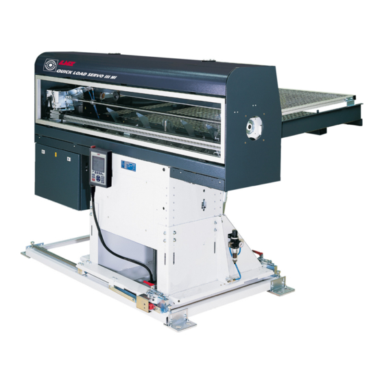
Magazine slope adjustment Retraction system Electrical control Access door Air filtering unit Interface plug (acc. to OEM requirements) (not shown here) Remote control (not shwn here) Carrier Feeding pusher (not shown here) Loading table Loading fingers QUICK LOAD SERVO III MI... - Page 16 CHAPTER 2: TECHNICAL DATA QUICK LOAD SERVO III MI...
-
Page 17: Chapter 3: Setting Into Operation
CHAPTER 3: SETTING INTO OPERATION CHAPTER 3: SETTING INTO OPERATION QUICK LOAD SERVO III MI... -
Page 18: Transportation
1.1. Description Depending on its destination, the Quick Load Servo III MI bar feed system may be delivered either on a pallet, or packed in a wooden crate. When sea or air transports it, the second solution is recommended. - Page 19 The notice instruction and the accessories are delivered in a separate package (E). • The bar feed system is held on the pallet by bolts and nuts (F). Take out the parts, and place them in an easily accessible area for mounting the bar feed system. QUICK LOAD SERVO III MI...
- Page 20 1.3. Preparation for mounting For mounting and installing the bar feed system, it is advisable to contact LNS or one of its agents. The latter cannot be held responsible for any malfunction resulting from an incorrect installation in which they did not take part.
-
Page 21: Mounting
Insert the fork located at the other end of the setting axle on the eyed support piece Designation Description Magazine loading table Slope adjusting axle Adjusting handle Eyed support piece on loading table Eyed support piece QUICK LOAD SERVO III MI... - Page 22 CHAPTER 3: SETTING INTO OPERATION 2.2. Mounting limiters The magazine of the Quick Load Servo III MI bar feed system can simultaneously accept bars of various lengths, from 130 mm to 1,600 mm. The maximum length (max. L.) The length...
- Page 23 SQ12 Retraction system in position switch On delivery, the elements of the retraction mechanism are not assembled on the bar feed system, as they can be installed either laterally or in line with the lathe. QUICK LOAD SERVO III MI...
- Page 24 Install the cross girders (G) against the rails (C). Loose the fixing screws (H) and (I) (16 in all) on each anchoring square. Install the four levelling screws (J) to guarantee the parallel of the rails. SQ12 QUICK LOAD SERVO III MI...
- Page 25 16. Proceed to the alignment as indicated on chapter 3/point 2.5. When the barfeeder is fixed to the floor, check the alignment of the switch with the key by moving the barfeeder backward and forward again to its working position. QUICK LOAD SERVO III MI...
- Page 26 Install the cross girders (G) against the rails (C). Loose the fixing screws (H) and (I) (16 in all) on each anchoring square. Install the four levelling screws (J) to guarantee the parallel of the rails. QUICK LOAD SERVO III MI...
- Page 27 16. Proceed to the alignment as indicated on chapter 3/point 2.5. When the barfeeder is fixed to the floor, check the alignment of the switch with the key by moving the barfeeder backward and forward again to its working position. QUICK LOAD SERVO III MI...
- Page 28 A hexagonal tube, delivered with the system, allows access to the adjusting screw from the top, through the loading table. • When the correct height is reached, tighten the screws (C) and proceed with the alignment of the bar feed system. • Remount the plate (A). QUICK LOAD SERVO III MI...
- Page 29 When the alignment is considered satisfactory, lock all screw nuts. Remove the eyed screws and install the plastic caps on the main access cover (the plastic caps should be among the parts in the separate package). QUICK LOAD SERVO III MI...
- Page 30 8 anchorage bolts (B) must be furnished by the client (Minimum M 10 x 100 mm) (Minimum 1/2" x 4"). Once the anchoring bolts are tightened, check the alignment again, and correct it if necessary. QUICK LOAD SERVO III MI...
-
Page 31: Electrical Connections
Choose methods of protection : the use of protective devices the introduction of signals compliance with safe work procedures ELECTRICAL CONNECTIONS See CHAPTER 4: ELECTRICS, section 4. INTERFACE. PNEUMATICAL CONNECTIONS See CHAPTER 5: PNEUMATICS, section 2. AIR FILTERING UNIT. QUICK LOAD SERVO III MI... - Page 32 3-16 CHAPTER 3: SETTING INTO OPERATION QUICK LOAD SERVO III MI...
-
Page 33: Chapter 4: Electrics
CHAPTER 4: ELECTRICS CHAPTER 4: ELECTRICS QUICK LOAD SERVO III MI... -
Page 34: Electrical Equipment
Please read the safety instructions provided at the beginning of this manual before handling the following devices. Particular attention should be given to the handling of electrical elements because of risks of electrocution. In case of possible electrical malfunctions, it is advisable to contact LNS or their local representative. 1.1. Description This chapter contains all of the elements regarding the electrical circuit of the bar feed system. - Page 35 Proximity switch for diameter adjustment 4.391 Proximity switch for pusher in home position SQ10 4.284 Main access cover safety switch SQ11 4.277 Magazine grid cover safety switch SQ12 4.291/4.292 Retraction system in position switch (incl. key) QUICK LOAD SERVO III MI...
-
Page 36: Electrical Cabinet
Relay : Motor M2 “Up” 4.606 Relay : Motor M2 “Down” 4.815 Circuit breaker 4A 4.242 Main disconnect switch R1-R5 4.925 Interface relay (not shown here) 4.769 Transformer 1ph 4.779 24 VDC Power supply 150W QUICK LOAD SERVO III MI... - Page 37 The power supply to the transformer is immediately interrupted to C60H avoid material damages. After having located and repaired the problem causing this interruption, reset the lever (B) of the circuit breaker. Designation Description Power in connecting terminal Lever on/off Power out connecting terminal QUICK LOAD SERVO III MI...
- Page 38 The transformer T2 has an output of 24 VDC and powers the rest of the barfeed. The transformer T2 output is protected by the fuse FU1 installed in a support in the electrical control cabinet. Although fuses seldom need replacing, is it advisable to keep some spare ones on hand. QUICK LOAD SERVO III MI...
- Page 39 230 V + ground power supply Power output to SERVO motor Battery (ordering number 4.714) Battery plug Emergency stop contact Encoder connecting plug Programmable controller / SERVO amplifier connecting plug Alarm and codes display of amplifier Cover QUICK LOAD SERVO III MI...
- Page 40 Run: The PLC is in RUN mode. This is the standard mode. Halt: The PLC is in HALT mode. Contact your LNS SA dealer. Error: The PLC is in a failure mode. Contact your LNS SA dealer. M1 slot: Usually this slot is left unused, and is used for software updates through flash (red) cards. Do not insert any flash card unless instructed by LNS SA.
- Page 41 Not in use Not in use Feed order Push order Not in use Not in use Programmable interface input Programmable interface input Not in use Not in use Programmable interface input Programmable interface input Not in use QUICK LOAD SERVO III MI...
- Page 42 .*&, < "! :# 1" ) ,+ 83# 9 & & / . & & / & & / 6 33 7& " 6 33 7& 83# 9 " 1" 1" . & . & & . & . & .*&...
- Page 43 =#!! 4 ( #A 3 : /C / ? $ "9 #: !4 3 " /C / ? . &, = > " " 1! # # .+&+ 1! ! < 1! 1! # # ; 4" B ! "< .
- Page 44 .'& . & . & = 7" ;*< ; < 0* + = 7" ;*< ; < & & ;=1< ;="< = 7" .'&+ 0* * #: !4 3 " . & & . & " ! " " * & ' "% ! &...
- Page 45 # " =# ! ! # ! #: !4 .*& #: !4 #: !4 .+& =3# 9 ; < ; < =" .'& DB ! ; < ; < & / & / " 4&$9 6 33 7& 6 33 7& 6 33 7&...
- Page 46 # "% !#83 # "% !#83 #A ! $1 B " ! " =# ! " # 1 "% . & # F1 !A "! ! " A#%#G " A !4 . & . & & / =" =" =" ="...
- Page 47 .+& .*&+ .*& "! H3 ;: " ! " J 1 !J J3 ! AJ #" K1 < 6 33 7& . &* .+& & " ! " " & ' "% ! & &...
- Page 48 = " 0*& 0*& 0*& 0*& " ! " " , & ' "% ! & &...
- Page 49 =#!! 4 ( #A 3 : /C / ? /C / ? = > ( A ! /C / ? $31% ? * /C / , - ; A< /C / ? " /C / & '+ > /C / ? >...
-
Page 50: Interface
3.1. Description The interface cable(s), between the bar feed system and the lathe is (are) provided by LNS. Although an example of an interface diagram is provided, the diagram for the interface corresponding to your device, essential when making the electrical connection, is located inside the electrical cabinet. - Page 51 After the loading and positioning of the new bar on the lathe spindle, relay R2 confirms the end of the loading cycle or the part feed out. The operational cycle of relay R2 (pulsed, latched, etc.) is controlled by Services parameters. QUICK LOAD SERVO III MI...
- Page 52 Emergency Stop button are available for connection in the Emergency Stop circuit of the lathe. 3.2.4. Options The options described below are an integral part of the standard equipment of the LNS bar feed systems. These signals, however, are not required for the proper operation of the devices, or the safety locking for protecting persons and materials.
-
Page 53: Chapter 5: Pneumatics
CHAPTER 5: PNEUMATICS CHAPTER 5: PNEUMATICS QUICK LOAD SERVO III MI... -
Page 54: Pneumatical Equipment
6 bars (90 PSI) is mandatory. 1.2. Layout of the pneumatic elements Designation Reference no. Description 3.636/3.638 Air filtering unit 3.407 Cylinder for feeding pusher locking mechanism 3.95020.A.30 Cylinder for loading channel up/down motion 3.656 Pneumatic valve battery QUICK LOAD SERVO III MI... -
Page 55: Air Filtering Unit
When the hose is connected, it should not lie on the ground because it could become damaged. Place clamp (A) around hose (B). Insert fitting (C) into hose. Tighten the flange (A) to make it airtight. QUICK LOAD SERVO III MI... - Page 56 To increase the pressure, turn it clockwise. To decrease it, turn it in the opposite direction. The operational pressure should be set at 5 bar. When the settings are done, lock the adjuster by pushing it downward. QUICK LOAD SERVO III MI...
-
Page 57: Pneumatic Valve
The air pressure switch is directly integrated into the pressure gauge. Set up procedure for the pressure switch: • Remove the glass of the pressure gauge • With a screwdriver, turn the setting screw • Place back the glass QUICK LOAD SERVO III MI... -
Page 58: Pneumatic Diagrams
CHAPTER 5: PNEUMATICS PNEUMATIC DIAGRAMS 4.1. Symbols Symbol Description Designation Pressure switch Pneumatic cylinder 3.301 Air filtering unit 3.305 Electro-valve YV1A / YV1B 4.2. Pneumatic diagram QUICK LOAD SERVO III MI... -
Page 59: Chapter 6: General Description
CHAPTER 6: GENERAL DESCRIPTION CHAPTER 6: GENERAL DESCRIPTION QUICK LOAD SERVO III MI... -
Page 60: Bar Magazine
1.1. Description Placed to the side of the Quick Load Servo III MI bar feed system, the loading magazine, 1,000 mm deep, can receive bars of various lengths, between 300 mm and 1,300 mm. To facilitate the moving of the bars on the magazine table, the latter is equipped with a grate on which the bars are placed. - Page 61 CHAPTER 6: GENERAL DESCRIPTION 1.2. Layout of the elements SQ11 Designation Description Magazine table Protection grid Rear limiter Slope inclination adjusting axle Fingers for bar selection Holding rod Bar safety stopper SQ11 Grid closed safety switch QUICK LOAD SERVO III MI...
- Page 62 A Service parameter, indicating the position of the loading table, must be changed. In this case, only a LNS or certified technician is allowed to move the magazine loading table. Procedure: The axle for setting the slope must be installed after the table has been moved.
- Page 63 CHAPTER 6: GENERAL DESCRIPTION 1.4. Limiters 1.4.1. Rear Limiter The magazine of the Quick Load Servo III MI bar feed system can simultaneously accept bars of various lengths, from 300 mm to 1,300 mm. The maximum length (max. L.) of the lathe spindle determines the length of bar stock that may be loaded.
- Page 64 (B). 1.4.3. Loading constant bars Quick Load Servo III MI may also be used as a loading magazine for piston rods, axles, or forged parts. A corresponding interface, however, is required if one wishes to attain minimum loading times.
-
Page 65: Loading Table
(C) connected to the loading table (D). The setting of the fingers is done automatically by the M2 electrical motor at the same time as the setting of the loading table (centerline height). The loading table of the Quick Load Servo III MI bar feed system has two functions: 1. Selection of material: When slide (A) is in a low position, feeding pusher (B) faces spindle (C). - Page 66 In order to ensure optimal loading, it is essential that the bar be perfectly aligned with the spindle, regardless of its diameter. Whenever the diameter or the profile is changed, the position of the table is automatically adjusted according to the diameter and the profile entered in the Quick Load Servo III MI by the operator.
-
Page 67: Pusher Carrier
CHAPTER 6: GENERAL DESCRIPTION 2.3. Positioning the roller supports Quick Load Servo III MI is delivered initially with 6 roller supports, laid-out to cover the entire length of the bar magazine. When limiter positioned during installation (See point 1.4.1 / Lmax.), move the... -
Page 68: Loading Pusher
Same-length bars may be loaded directly with a loading pusher without using the feeding pusher. To do this, a special extended loading pusher, available as an option, is required. Selected parameters must then be chosen; see Chapter 7 / point 4.2.7. QUICK LOAD SERVO III MI... -
Page 69: Feeding Pusher
CHAPTER 6: GENERAL DESCRIPTION 6-11 FEEDING PUSHER 5.1. Description Three feeding pushers are necessary to cover the entire range of the Quick Load Servo III MI barfeed system. Each pusher has a defined range of operation : Pusher diameter Ordering Nr Diameter Range **6,35 mm (1/4") - Page 70 • Tighten the fastening screws so that they lodge into the groove of the pusher. • Check to see that the mechanical stop sleeve is properly positioned (see next section) QUICK LOAD SERVO III MI...
-
Page 71: Belt
• With the lever (C) push the motor up to tighten the dented belt (A). • Holding the belt taut, tighten the fixing screws (B). • Remove the lever and close the main access cover. QUICK LOAD SERVO III MI... -
Page 72: Retraction
To facilitate these tasks, the Quick Load Servo III MI is equipped with a retraction system, which allows the operator to move the bar feeder. - Page 73 To move the bar feed system, unlock the hooks by lifting the latching handles (D). An autolock device (F) will prevent the bar feed system to move back. • To bring the bar feed in operational position, lift the auto lock device. QUICK LOAD SERVO III MI...
-
Page 74: Options
The loading procedure is simplified, and the loading cycle time can be reduced with specific interface and adaptations. This kit includes a loading pusher ø12 mm for shaft loading, adjustable to the part length. Description Reference no. One shot shaft loading 021.018.012 QUICK LOAD SERVO III MI... - Page 75 The adapter must be adapted to the outside diameter of the tube (by turning the outside diameter of the adapter), and then be mounted on the tip of the 25 mm pusher. QUICK LOAD SERVO III MI...
- Page 76 6-18 CHAPTER 6: GENERAL DESCRIPTION QUICK LOAD SERVO III MI...
-
Page 77: Chapter 7: Operation
CHAPTER 7: OPERATION CHAPTER 7: OPERATION QUICK LOAD SERVO III MI... -
Page 78: Powering Up
Please read the safety instructions provided at the beginning of this manual before handling the following devices. The motor of the QUICK LOAD SERVO III MI bar feed system is equipped with a built-in absolute encoder that continuously controls the position of the pusher. -
Page 79: Remote Control
The remote control has five distinct segments, namely: display (A), function keys (B), directional keys and numeric pad (C), modes buttons with STOP, MENU and HELP buttons (D), and the emergency button (E). QUICK LOAD SERVO III MI... - Page 80 Switch to manual mode Jump to next menu Pusher forward (picture Move the loading table up + load a new bar reversed) into the loading table Pusher reverse (picture Move the loading table down reversed) QUICK LOAD SERVO III MI...
- Page 81 3 seconds to validate the change. Start sequence Decrement data in offset correction mode Enter the loading table calibration mode Lower the loading table (in calibration mode) Rise the loading table (in calibration mode) QUICK LOAD SERVO III MI...
- Page 82 2.5.3. HELP key The HELP key displays useful information about the software version, the firmware of the critical components, the current status of the inputs and outputs of the system. QUICK LOAD SERVO III MI...
-
Page 83: Set Up
Depending on the bar stocks to feed, a changeover of the pusher may be necessary. In this case, please refer to CHAPTER 6, section 5.2. Pusher replacement of this user manual. QUICK LOAD SERVO III MI... - Page 84 The radius of the grip is greater than the radius of the bar. The jaws press against only 3 points at 120 degrees. 60° Correct : Modify the centres of the jaws to obtain 2 times 6 support clamping points at 60 degrees. QUICK LOAD SERVO III MI...
- Page 85 + 1 mm), but should always be larger than that of the diameter of the feeding pusher. For inserting and removing the spindle reductions, move the bar feed system using the retraction device (see CHAPTER 6, section 7. RETRACTION for further information). Spindle reduction tubes are available from LNS, upon request. QUICK LOAD SERVO III MI...
-
Page 86: Settings
4.1. Description The QUICK LOAD SERVO III MI has several parameters and functions allowing the operator to configure it so that it adapts as closely as possible to the lathe on which it is installed, as well as to the production mode under way. - Page 87 Torque for the part feeding Language setup Allows the access to the other languages Miscellaneous functions • Reference point request • Timings on lathe’s clamping device Service setup Reserved maintenance technicians and for unlocking features / displays. QUICK LOAD SERVO III MI...
- Page 88 The feed-out length (Lt) includes the part length (Lp), the cut-off tool width (C) and the face-off length (not represented on the picture, depending on the program). Variable face-off distance Distance from the face of the lathe’s chuck to the cutting position. QUICK LOAD SERVO III MI...
- Page 89 With this system, the setting is the same for any bar length. More information the section 7. TOP-CUT POSITION of this chapter. QUICK LOAD SERVO III MI...
- Page 90 With this system, the setting is the same for any bar length. More information the section 7. TOP-CUT POSITION of this chapter. QUICK LOAD SERVO III MI...
- Page 91 This parameter allows to define the clearance between the bar stock and the pusher after the part feed out, when the clamping device closes and the bar is rotating again. This value should be set so that the pusher never touches any rotating part (bar or spindle, or spindle liner). QUICK LOAD SERVO III MI...
- Page 92 This parameter should only be used with a physical limiter on the loading magazine to avoid the loading of longer bars, which could lead to damages on the lathe. QUICK LOAD SERVO III MI...
- Page 93 Please contact your LNS agent for further information on this application. Feed rate for part feed out (may be not visible) This parameter allows to adapt the feed rate to the actual weight of the bar, for example when feeding aluminium bar stocks.
- Page 94 This parameter is used to deactivate the M function receipt of the turret if this function is not used in the lathe interface. In this case, a timer can be used to give the receipt. QUICK LOAD SERVO III MI...
- Page 95 One Shot shaft loading This parameter enables the One Shot shaft loading, where the shaft is directly brought into top-cut position by the loading pusher. Please contact your LNS agent for further information on this application. QUICK LOAD SERVO III MI...
- Page 96 In this application, the feeding pusher is used as a depth end stop, to safely load shafts manually. This application might not work on lathes with “door open” signal connected to the safety line, where no pusher movement is allowed when the door of the lathe is open. QUICK LOAD SERVO III MI...
- Page 97 With this system, the setting is the same for any bar length. More information the section 7. TOP-CUT POSITION of this chapter. QUICK LOAD SERVO III MI...
- Page 98 The contrary applies if the specific weight of the bars is low. Torque rate during loading according to bar diameter (%) Same principle as for the couple fast forward, applied this time to loading. QUICK LOAD SERVO III MI...
- Page 99 Time for clamping device to open (may be not visible) In the case of a clamping device with jaws, sometime may be provided to prevent any movement before the clamping device is completely open. QUICK LOAD SERVO III MI...
- Page 100 • Active part: shows the part ID currently in use. • Total parts: shows the total number of parts stored in the library. • Enter part ID: type the ID of the part to recall and load. QUICK LOAD SERVO III MI...
- Page 101 • Active part: shows the part ID currently in use. • Total parts: shows the total number of parts stored in the library. • Enter part ID: type the ID of the part to delete. QUICK LOAD SERVO III MI...
- Page 102 Changing these values can damage the devices and create safety issues. Therefore, these parameters are protected with a password, and only LNS (or certified) technician is authorized to modify them. 1. Barfeed These parameters set the values of speed, position and torque for a functioning barfeed system...
- Page 103 Ethernet Interface (disabled/enabled) settings Ethernet interface type (1: MTCONNECT / 2: OKUMA / 3: MORI SEIKI / 4: MAZAK) CPU – IP Address CPU – Subnet mask CPU – Default gateway ANYBUS – IP Address QUICK LOAD SERVO III MI...
- Page 104 1. Software This screen displays the current software running the barfeeder and its version. 2. Interface This screen shows the current signals being sent / received through the interface between the barfeed and the lathe. QUICK LOAD SERVO III MI...
- Page 105 This screen shows the current input signals being used in the barfeed. 4. Outputs This screen shows the current output signals being used in the barfeed. 5. Alarms list This screen shows the history of the last 10 alarms. QUICK LOAD SERVO III MI...
- Page 106 This screen helps entering and monitoring specific bits (status in green/red), and register values (value in left box). 7. Force Ethernet signals This screen helps force interface signals through the ethernet cable to troubleshoot the communication between the barfeed and the lathe. QUICK LOAD SERVO III MI...
-
Page 107: Automatic Cycle
The pusher must be adapted to the bar stock diameter and to the spindle inner diameter (including spindle liner). • The pushing force must be adapted to the bar stock material. • On the lathe, the clamping device must be adapted to the bar stock diameter. QUICK LOAD SERVO III MI... - Page 108 COMPLETE HEADSTOCK PART FEED HOME LOADING FINGER MEASURES RETURN TO THE BARSTOCK MAIN PART CLOSE COLLET PROGRAMM LOADING FINGER MACHINE PART MOVES TO THE END OF STOKE CUT-OFF PART LOADING FINGER MOVES BACK TO REFERENCE QUICK LOAD SERVO III MI...
-
Page 109: End Of Bar Position
The remote command displays the following text : "PARMETERS RELATED TO". Press twice the key attributed to the icon [PAGE DOWN]. [ENTER] The remote command displays the following text : "SETTINGS FOR POSITIONING". Press the key attributed to the icon [ENTER]. QUICK LOAD SERVO III MI... - Page 110 • Press the key [FWD] and advance the pusher to the desired position [ENTER] (see previous page). • To validate the new end of bar position, keep [ENTER] pressed until the icon disappears. [ESC] To exit the set mode, press the keys [ESC] or [STOP]. [STOP] QUICK LOAD SERVO III MI...
-
Page 111: Top-Cut Position
No bar stock in the loading Icon [+/-] Icon [TEACH IN] channel Loading with extended loading Icon [+/-] pusher Setting by offset correction: jump to point 6 Setting by teach in: jump to point 7 [+/-] [+/-] By offset correction: QUICK LOAD SERVO III MI... -
Page 112: Powering Down
When powering off the barfeed, make sure the pusher is in reference position, table in lower position, and no bar stock is present in the guiding element. To power down, turn the switch to the left, to the 0off position. QUICK LOAD SERVO III MI... -
Page 113: Chapter 8: Malfunctions / Maintenance
CHAPTER 8: MALFUNCTIONS / MAINTENANCE CHAPTER 8: MALFUNCTIONS / MAINTENANCE QUICK LOAD SERVO III MI... -
Page 114: Alarms
Please read the safety instructions provided at the beginning of this manual before handling the following devices. Particular attention should be given to the handling of electrical elements because of risks of electrocution. In case of possible electrical malfunctions, it is advisable to contact LNS or their local representative. 1.1. PLC alarms... - Page 115 Check the switch SQ2. AL12 - FAILURE WHILE LOADING TABLE MOVING UP ! Description A mechanical obstruction prevented the table from moving up. Solutions Check that there is no mechanical obstruction Check switches SQ1 and SQ2. QUICK LOAD SERVO III MI...
- Page 116 The PLC does not detect input (I11 – SQ4). Solutions Check the switch SQ4. Check the motor M2. AL18 - FAILURE ON SWITCH SQ5 ! Description The PLC does not detect input (I12 – SQ5). Solutions Check the switch SQ5. QUICK LOAD SERVO III MI...
- Page 117 Check the part program in the lathe. AL23 - LOADING TIME ELAPSED ! Description The time allowed to reach the position has been exceeded. Solutions Remove the bar stock from the spindle. Restart the top cut cycle. Check the part settings. QUICK LOAD SERVO III MI...
- Page 118 Check the wiring of the clamping device signal A1. AL28 - M-CODE PART BEGIN NOT IN SYNC ! Description The parts counter and the chuck openings do not match. Solutions Check the lathe program. Check the quantity of chuck openings per part. QUICK LOAD SERVO III MI...
- Page 119 AL39 - CUT OFF FEED FAULT ! Description The values do not match. Solutions Check length more than 0mm. Check length not more than 50mm. Check length not more than remnant length. Part ID must in 9990-9999 range. QUICK LOAD SERVO III MI...
- Page 120 M-Code request parameter disabled. Solutions Check that the M Code request is active. AL45 - POSITIONING COULD NOT BE ACHIEVED ! Description An obstacle prevented the progress of the pusher. Solutions Remove any mechanical obstruction. QUICK LOAD SERVO III MI...
- Page 121 Replace the battery as soon as possible. Do not shut down the barfeeder until the battery has been replaced. AL50 - AMPLIFIER FIRMWARE NOT COMPATIBLE ! Description The firmware of the servo drive is not compatible with the LNS software. Solutions The amplifier must be replaced. Please contact your LNS agent. QUICK LOAD SERVO III MI...
- Page 122 Particular attention should be given to the handling of electrical elements because of risks of electrocution. In case of possible electrical malfunctions, it is advisable to contact LNS or their local representative. Alarm code (note 2)
-
Page 123: Factors Affecting Performance
The alignment of the bar feed with the axis of the spindle must be perfect. It is essential that the alignment of the bar feed system is done in accordance with the instructions indicated in Chapter 3. Setting into operation. QUICK LOAD SERVO III MI... - Page 124 In general, the difficulty increases with the specific weight of the bar. Steel bars are relatively easy to guide. Because of their great flexibility and specific weight, brass bars are relatively difficult to guide at high speeds. Aluminium bars are very easy to guide. QUICK LOAD SERVO III MI...
-
Page 125: Maintenance
At no time should cleaning products come into contact with electrical components. 3.5. Spare parts Without the written consent of LNS SA, no addition or modification of the machine or spare parts can be undertaken. LNS SA assumes no responsibility when using spare parts which were not provided by LNS SA. - Page 126 8-14 CHAPTER 8: MALFUNCTIONS / MAINTENANCE QUICK LOAD SERVO III MI...
-
Page 127: Chapter 9: Appendices
CHAPTER 9: APPENDICES CHAPTER 9: APPENDICES QUICK LOAD SERVO III MI... -
Page 128: Ordering Form
CHAPTER 9: APPENDICES ORDERING FORM This form should be photocopied, duly filled out, and returned to your retailer or nearest LNS agent Company name: Person in charge: Address: ZIP: City: Country: Phone: Fax: Type of device: Serial number: Qty. Ordering no. -
Page 129: Lns Addresses & Contacts
4621 East Tech Drive www.Lns-america.com CINCINNATI, OHIO 45245 TEL. +1 513 528 56 74 FAX +1 513 528 57 33 AGENTS LNS LNS Europe : www.lns-europe.com LNS America : www.lns-america.com LNS Asia : www.lns-asia.com QUICK LOAD SERVO III MI... -
Page 130: Programming Example
X, Z, G, F, T, S, M, ... N... N... END OF PROGRAM (LOOP) Important: The above is an example only. Programming may change according to the interface between the lathe and the bar feed. QUICK LOAD SERVO III MI...
Need help?
Do you have a question about the QUICK LOAD SERVO III MI and is the answer not in the manual?
Questions and answers