Table of Contents
Advertisement
Advertisement
Table of Contents

Related Manuals for AURATON 2030 RTH


Summary of Contents for AURATON 2030 RTH
- Page 3 Operation under loads up to 16 A – The AURATON RTH receiver is equipped with a relay capable of operating with the load up to 16 A.
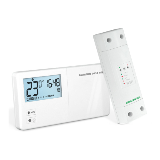
- Page 4 Description of the AURATON 2030 and 2030 RTH temperature regulator On the right side of the front panel of the regulator you will find a sliding cover. There are buttons under the cover. You can replace batteries by removing the cover completely.
- Page 5 NOTE: In order to preserve the parameters programmed, duration of the replacement operation must not to exceed 30 seconds. 11. Transmission symbol ( ) – AURATON 2030 RTH only Indicates ongoing communication with the RTH receiver. 12. Relay activation indicator ( A segment informing about the operating state of the controlled device.
- Page 6 Description of the AURATON RTH receiver The AURATON RTH receiver cooperates with the AURATON 2030 RTH wireless receiver. The receiver is installed on the heating or air conditioning device and can operate under the load of 16 A. hole for fastening the receiver...
- Page 7 Selecting the proper location for the AURATON 2030 / 2030 RTH temperature regulator Proper operation of the regulator is greatly affected by its location. Installing it in a place with no air circulation or exposed to direct sunlight causes improper regulation of temperature. In order to ensure proper operation, the regulator must be installed on an interior wall of a building (partition wall).
- Page 8 Fastening the temperature regulator to the wall 1.Drill two holes 6 mm in diameter in the wall (use the template attached to the manual to mark the spacing between these holes). 2.Insert plastic wall plugs (included in the kit). 3.Screw in the left screw with a 3 mm clearance. 4.Put the regulator over the screw head and slide it to the left (pay attention to the key-hole in the rear wall of the regulator).
- Page 9 It is recommended that the installation is performed by a qualified specialist. 1. Take off protective covers from the lower and upper part of the AURATON RTH receiver. protective cover 2. Take off cable tie clamps from the lower and upper part of the AURATON RTH receiver.
- Page 10 Fastening the RTH receiver to the wall To fasten the AURATON RTH receiver to the wall: 1) Remove protective covers from the lower and upper part of the regulator. (See chapter: “Fastening the RTH receiver”). 2) On the wall, mark the location of holes for fastening screws.
- Page 11 ) appears on the display. Release the button - the regulator transmits the pairing signal for 5 seconds. 3. A properly completed pairing process is signalled by the LED on the AURATON RTH receiver no longer flashing green and the receiver reverting back to normal operation.
- Page 12 - the regulator transmits the pairing signal for 5 seconds. 3. A properly completed deregistering process is signalled by the LED on the AURATON RTH receiver no longer flashing red and the receiver reverting back to normal operation.
- Page 13 Starting-up the regulator for the first time After the proper placement of batteries in the battery holder, all segments of the LCD display are displayed (display test) for one second and after that, the software version number is displayed. Following that, the regulator automatically enters the time setting mode;...
-
Page 14: Setting The Clock
Setting the clock In order to set the clock: 1. Press the [cl] button until the SET_z icon is displayed, informing that the regulator has entered the time setting mode, and the hour field starts flashing. 2. Using the‚ [updo] buttons, set the desired hour value. - Page 15 PROGRAMMING The memory of the regulator allows for saving up to eight programs for weekdays, eight programs for Saturday and the same for Sunday. This allows for exceptionally precise planning of temperature in the building depending on the time of day. Factory programs (for modification) Weekdays...
- Page 16 2. Assigning a day to the program : Press the [1---7] button to select days to be assigned to the program. A segment with days of week will start flashing in the top part of the display. Using the, [updo] buttons, you can assign: –...
- Page 17 , vacation and anti-freezing temperature. The AURATON 2030 / AURATON 2030 RTH regulator allows for setting three kinds of temperature: manual temperature ( ) – within the range from 5°C to 30°C, vacation temperature ( ) – within the range from 5°C to 30°C, anti-freeze temperature ( ) –...
-
Page 18: Manual Control
Manual control When, for any reason, you would like to suspend execution of the program for a certain period of time, the temperature can be set manually for a specified time. In such a case you have to: 1. Press the [auto] button. - Page 19 Anti-freeze mode The regulator is equipped with a setpoint for the anti-freeze temperature. This setpoint can be set within the range from 4 to 10°C. (Factory set at 7°C) The anti-freeze mode is used during a prolonged period of absence or outside the heating season and is designed to prevent water in the heating system from freezing.
- Page 20 (AURATON 2030 only) To enter the configuration settings change mode press the‚ [updow] buttons simultaneously and hold them for 5 seconds until the display backlight starts flashing. 1.BACKLIGHT COLOUR CHANGE: Flashing backlight indicates that you...
- Page 21 3. DELAY CHANGE (AURATON 2030 only) Delay is designed to prevent switching the controlled device on and off too frequently e.g. due to a momentary whiff of air caused by opening a window. This mode is signalled by flashing text ”90:SE”.
- Page 22 The AURATON T-2 thermometer provides information about the current temperature only, without the capability of changing it manually. A) The manual setpoint – pairing the AURATON 2030 RTH regulator with the RTH receiver allows for setting the temperature manually and controlling...
- Page 23 T-2 thermometer only. This feature allows for regulating the temperature in a room other than the one where the AURATON 2030 RTH regulator is placed. An example: you want the temperature in the “children’s room” to be always at 22°C, however you do not want children to be able...
- Page 24 AURATON W-1 window position sensor paired, therefore the relay is controlled by the paired AURATON 2030 RTH regulator and/or the AURATON T-2 thermometer. When at least one H-1 handle is paired with the RTH receiver, the relay is controlled in the following manner: A) The window is closed or trickle-ventilated (micro-ventilation).
- Page 25 24 hours occurs only after losing the signal from the T-2 thermometer. When only the signal from the AURATON 2030 RTH is missing, the RTH receiver automatically maintains the last memorised setpoint from the AURATON 2030 RTH regulator and also signals an error.
-
Page 26: Replacing Batteries
ź the AURATON H-1 window handle). Additional information and notes The AURATON 2030 RTH regulator and/or the T-2 thermometer must be ź installed at least 1 metre from the RTH receiver (too strong signal from the transmitters can cause interference). - Page 27 INFO function is invoked. When any button is pressed and held for a while, the backlight is switched on instantly, and the corresponding function is executed after the specific time of pressing the button has elapsed. The AURATON 2030 regulator connection schematics AURATON 2030 230 V...
- Page 28 The AURATON RTH receiver connection schematics 230 V heating device e.g. a gas furnace ALARM RESET AURATON 2030 RTH AURATON RTH AURATON 2030 RTH 230 VAC electric heating device Max. 230V 16 A Max. 230V ALARM RESET AURATON RTH AURATON 2030 RTH...
-
Page 29: Technical Specifications
5 week days + Saturday + Sunday Working mode control: LED (the RTH receiver) / LCD (the regulator) Maximum load: AURATON 2030 ~ 8A 250VAC (inductive 5A) AURATON RTH ~ 16A 250VAC Power supply AURATON 2030 2x AA alkaline battery... - Page 30 A template for drilling holes for fastening the AURATON RTH receiver (1:1 scale)
- Page 32 www.auraton.pl...
Need help?
Do you have a question about the 2030 RTH and is the answer not in the manual?
Questions and answers