Table of Contents
Advertisement
Advertisement
Table of Contents

Related Manuals for AURATON 3021 RT


Summary of Contents for AURATON 3021 RT
- Page 1 3021 RT 3021 DS 3021 P 3021 OWNE R’ S MA NU A L...
- Page 2 Thank you for purchasing the latest temperature controller based on an advanced microprocessor. AURATON 3021 / 3021 P / 3021 RT / 3021 DS 3 independent temperature settings Day, night, anti-freeze. 9 independent temperature programs Including 6-user defined ones. Backlit LCD display Backlit LCD display to control the device in areas with poor lighting.
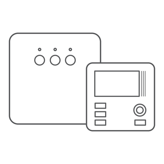
- Page 3 Temperature controller explained On the front of the enclosure, there are four function keys, backlit LCD display and temperature control knob with the OK button. LCD display setting knob with temperature integrated OK setting key button selection mode select key: date/time/day of day mode week setting key...
- Page 4 Display 1. Day of week ( ) – Indicates the current day of the week. Each day has a number assigned. 2. Temperature – In normal operating mode, the controller displays the temperature of the room it is installed in. 3.
- Page 5 9. Manual control indicator ( ) Appears if the programmed mode is switched off. (see: „Manual control mode”) 10. Transmission symbol ( ) – AURATON 3021R only. Indicates ongoing communication with the RT receiver. 11. Controller power on indicator ( Indicates the operating status.
- Page 6 Description of the RT receiver The AURATON RT receiver cooperates with the AURATON 3021R wireless receiver. The receiver is installed on the heating or air conditioning device and can operate under the load of 16A/10A. diode indicating that button for unpairing...
- Page 7 Legend – description of LED signalling The LED light’s green – the output device is off (the contacts COM and NC are closed). The LED light’s red – the output device is on (the contacts COM and NO are closed). The LED flashes green –...
- Page 8 If devices with higher power are connected, the cables should be replaced with ones of appropriate cross-sections. NOTE: When installing an AURATON RT receiver, make sure that the power supply is switched off. The receiver should be installed by a professional.
- Page 9 1. Take off the cover of the front part of the AURATON RT receiver by un- screwing the screws half way out. 2. Connect the heating device to the terminals of the control connection of the AURATON RT receiver. Follow...
- Page 10 (5 mm). 4. Put the wall plugs in the drilled holes. 5. Fasten the AURATON RT receiver to the wall using screws so that the receiver is well fastened. Note: If the wall is wooden, there is no need to use wall plugs.
- Page 11 Selecting proper location for temperature controller Controller location largely affects its proper operation. When locat- ed in a place without air circulation or exposed to direct sunlight, the controller may not control the temperature properly. The controller should be located on an internal wall of a building (partition wall) in a place with free air circulation.
- Page 12 Wiring your AURATON 3021 To connect the wiring, remove the enclosure as described below: Wiring terminals are located in the controller back wall, under the plastic cover. screw cover...
-
Page 13: Battery Installation/Replacement
The battery socket is located inside the controller, at the front of the enclosure. To install the batteries, remove the controller enclosure as described in the “Wiring your AURATON 3021” section. NOTE: We recommend using alkaline bateries to supply AURATON controllers. - Page 14 ON 3021” section. Fixing the controller to the wall To fix the AURATON 3021 controller to the wall: 1. Remove the enclosure (as described in the “Wiring your AURATON 3021” section). 2. Drill 2 holes diameter 6 mm in...
- Page 15 3. Place plastic plugs in the drilled holes. 4. Screw the back of the controller enclosure to the wall with the two screws provided. 5. Replace the controller enclosure. NOTE: No expansion bolts are needed for wooden walls. Just drill holes di- ameter 2.7 mm (instead of 6 mm) and screw the screws directly into the wood.
- Page 16 1. Pairing of the AURATON 3021 RT controller with the AURATON RT receiver is initiated by pressing the right pairing button ( – a single sound signal is emitted – on the AURATON RT receiver and by holding it pressed for at least 3 s until the LED diode starts blinking with green light (double sound signal) –...
- Page 17 If more errors occur, all devices must be unpaired by RESETTING the AURATON RT receiver (see „RESET – Unpairing all devices paired with the AURATON RT receiver”) and then an attempt must be made to pair the devices again. NOTE: Only 1 temperature controller may be paired with one receiver.
- Page 18 Unpairing of the controller and the RT receiver 1. Unpairing of the AURATON 3021 RT controller from the AURATON RT receiver is initiated by pressing the left unpairing button ( on the receiver and holding it for at least 3 seconds until the LED diode starts blinking red - then the button must be released.
- Page 19 2 seconds by the diode color changing to green and then switching off for a short time. NOTE: If the power supply of the AURATON RT receiver is switched off and then switched on after the RESET, the receiver automatically goes into the “pairing”...
- Page 20 Starting the controller for the first time After correct installation of the batter- ies, the LCD will display, for a second, all segments followed by the firmware version number. After a while, the controller will auto- matically switch to time setting mode. A blinking component on the display is in edit mode.
- Page 21 NOTE: If no key is pressed for 60 seconds in the initial edit mode, the default time 12:00 and Monday will be auto- matically set. NOTE: While programming any other functions, if no key is pressed for 10 seconds, this will be interpreted as pressing the key.
- Page 22 Saturday – Sunday heaters will operate according to the day temperature ( between 06:00 and 23:00 default temperature settings: day temperature – 21,0°C night – 19,0°C anti-freeze temperature – 7,0°C temperature of the external sensor – 40.0°C (Auraton 3021 DS only)
- Page 23 Programming day nd night temperatures With AURATON 3021 2 temperatures can be programmed: • Day temperature ( ) – from 5 to 30°C • Night temperature ( ) – from 5 to 30°C • Temperature of the external sensor ( ) - from 10 to 55°C...
-
Page 24: Programming Introduction
PROGRAMMING INTRODUCTION Timeline The timeline on the LCD is divided to 24 sections. Each corresponds to 1 hour of the day. Black rectangles above the timeline indicate day temperature set for the specific hours. Night temperature is set when no rectangles are present. -
Page 25: Factory Programs
Factory programs Proper program should be set for every day of the week so that the controller know when to switch between the night and day temperatures. To do so, you can use one of the factory presets available (from 0 to 2): 0 –... -
Page 26: Weekly Programming
PPROGRAMMING Weekly programming To program the controller, set the day temperature intervals for individual days of the week. At other time, night temperature will be set. Sample controller setting from Monday to Sunday. Outside the inter- vals programmed, the night temperature will be se. Day temperature Monday 5:00 –... -
Page 27: Program Selection
PROGRAM SELECTION To set the program: 1. Press the key. Program number segment will start blinking. 2. Press the key as many times as required to set the day of the week for the program. 3. Press the key several times and select the program number re- quested. - Page 28 MODIFYING USER-DEFINED PROGRAMS (prog. 3...8) To set the program: 1. Press the key. Program num- ber segment will start blinking. 2. Press the key as many times as required to set the day of the week for the program. 3. Press the key several times to select the program number required.
-
Page 29: Manual Control
5. Press the key to select day (rectangle on) or night tempera- ture (no rectangle). Then, select the time interval for the tempera- ture selected with the knob. 6. By pressing the key and select- ing time interval the entire pro- gram is modified. - Page 30 The controller will wait to set what of the two temperatures should be held (day or night). Press the key or use the knob to change the setting. Press the key to acknowledge the selection. Option 2 If, for some reasons, you would like to suspend program execution, for example because of a longer party, and the controller has already started to decrease temperature for the night setting (the symbol is displayed), and you whish to keep comfortable temperature...
-
Page 31: Anti-Freeze Temperature
Anti-freeze temperature If you leave for a longer time, you can set the anti-freeze tempera- ture. This will prevent from the consequences of freezing of water in the heating system by automatic temperature setting to 7°C. To set the anti-freeze program, select the program 0 at the desired day of week. -
Page 32: Configuration Settings
Configuration settings Configuration settings are presented for changing in the following order: delay change hysteresis offset Heating mode / Pr Off/Pn On Air conditioning change change (3021 / 3021 DS (3021 DS only) mode only) To enter the configuration settings change mode press the‚ buttons simultaneously and hold them for 3 seconds until the display backlight starts flashing. - Page 33 For the HI 4 hysteresis, when the tempera- ture is set to 20°C, the boiler will be switched on at 19.6°C, and switched off at 20.4°C. The hysteresis change mode is signalled by flashing text HI. You can change hysteresis settings with turn the knob clockwise.
- Page 34 Confirm the setting by pressing the button. The regulator will proceed to change the next parameter. 4. OFFSET CHANGE Offset allows for calibrating temperature indications within the tolerance of ±3°C. E.g. the temperature regulator indicates that the room temperature is 23°C, whereas a regular mercurial ther- mometer placed alongside indicates 24°C.
-
Page 35: Special Situations
Special situations • When 3 consecutive transmissions (after 15 minutes) from the AURATON 3021R regulator are lost, an error is signalled on the RT receiver (LED flashing continuously red and green). The RT receiver starts executing the ON - OFF cycle memorised during the last 24 hours of operation until the problem is removed. - Page 36 Additional information and notes • The AURATON 3021R regulatormust be installed at least 1 metre from the RT receiver (too strong a signal from the transmitters can cause interference). • At least 30 seconds must elapse between switching the relay off and on.
-
Page 37: Cleaning And Maintenance
• While programming any function, if no key is pressed for 10 seconds, this will be interpreted as pressing the key. • The control functions of the controller can be switched on and off (e.g. after heating season) by holding the key pressed for a while. - Page 38 The RT receiver connection schematics control heating power device ~230V AURATON 3021 e.g. a gas furnace Max. ~230V electric heating device AURATON 3021 Max. ~230V 16 A...
- Page 39 The AURATON 3021 regulator connection schematics control HEATING DEVICE ~230V AC e.g. a gas furnace ~230V AC ELECTRIC HEATING DEVICE MAX ~230V 16A PROTECTIVE...
- Page 40 The controller in the Dual Sensor (DS) version (with an additional temperature sensor) A controller fitted with an additional socket enables connecting an external temperature sensor (2.5 m is supplied). In order for the external sensor to be properly detected, first the sensor must be connected and then the supplied batteries must be installed in the controller.
- Page 41 The controller in the Dual Sensor version (with an additional tempe- rature sensor) has the emergency transmitter operation function. When the voltage battery is too low (the indicator on the display), the user may decide to switch the transmitter off or to switch it on permanently.
-
Page 42: External Temperature Sensor
External temperature sensor (AURATON 3021P i 3021 DS) In AURATON 3021 P it is possible to connect an external temperature sensor with the 2.5m cable. In the default configuration the control- ler will display the temperature from the internal temperature sen- sor. -
Page 43: Technical Data
Technical data Operating temperature range: 0 – 45°C Temperature measuring range: 0 – 35°C Temperature control range: 5 – 30°C Range of temperature control 10 – 55°C of the external sensor: Hysteresis: ±0,2°C / ±0,4°C Default temperature settings: day 21°C / night 19°C Additional function: Anti-freeze mode Operating cycle:... - Page 44 20190213...
Need help?
Do you have a question about the 3021 RT and is the answer not in the manual?
Questions and answers