Advertisement
Quick Links
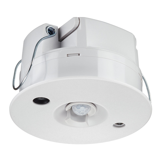
DUS360CR / DUS360CR-DA
Low profile 360° ceiling sensor
To reduce the risk of device failure, do not expose this device to rain or moisture. Installation, programming and maintenance must be
carried out by qualified personnel. All local wiring and electrical regulations must be followed when installing device.
This is a SELV (Safety Extra Low Voltage) device and
must be isolated and segregated from mains and other
wiring as per the local wiring rules
To reduce the risk of device failure and to avoid damage to the unit, disconnect
network and device power before installation or servicing. It is recommended that
an electrician perform this installation.
Do not expose this device to rain or moisture. Connect the cable shield to the
provided shield termination on the device connection port. If no shield termination
is provided on the device, connect the cable shield to the equipment grounding
conductor of the supplying branch circuit(s). Installation, programming and
maintenance must be carried out by qualified personnel.
Lens Pattern
4
3
3
2
1
6m
0
1
2
3
Hardware
120º PIR shield
Light level
sensor
PIR sensor
WARNING
8m
2
1
0
1
2
- Network sign-on button
- IR receiver
- Red LED indicator
Read Instructions – We recommend that you read these
instructions prior to commencement of installation.
Check Connections – Ensure that all wiring terminals are securely
connected.
Mounting Location – For indoor use only. Select sensor locations
as per user requirements. Note that the optimal locations for PIR
and PE use may be different, requiring multiple sensors in the
same area. This device is suitable for plenum use.
Data Cable – Use screened, stranded RS-485 data cable with four
twisted pairs. Segregate from mains cables by at least 300mm.
Connect devices in a 'daisy chain' configuration. A data cable that
is connected to an energized device is live. Do not cut or terminate
live data cables.
Power supply – This device must be powered by a certified class
2 energy limited source for North America, or SELV for EU regions.
Installation – Installation must be done in accordance to the local
wiring code (or wiring rules). Installation of the home and building
3
4
automation and control system shall comply with HD60364-4-
41. The temperature limits and current-carrying capacities of
the communication wires specified in HD 384.5.523 shall not be
exceeded. Network Topology for installation is Daisy Chain.
Dimensions
Advertisement

Related Manuals for Philips dynalite DUS360CR


Summary of Contents for Philips dynalite DUS360CR
- Page 1 DUS360CR / DUS360CR-DA Low profile 360° ceiling sensor To reduce the risk of device failure, do not expose this device to rain or moisture. Installation, programming and maintenance must be carried out by qualified personnel. All local wiring and electrical regulations must be followed when installing device. Read Instructions –...
-
Page 2: Product Specifications
DUS360CR Installation Instructions Rev 02 Specifications subject to change without notice Dynalite manufactured by WMGD Pty Ltd (ABN 33 097 246 921) Unit 6, 691 Gardeners Road Mascot NSW 2020 Australia Tel: +61 2 8338 9899 Fax: +61 2 8338 9333 E-Mail: support.controls@philips.com Web: http://philips.com/dynalite...