Table of Contents

Related Manuals for Univex SRM12


Summary of Contents for Univex SRM12
- Page 1 SRM12 PLANETARY MIXER PARTS & SERVICE MANUAL SRM12 REV B Persons under the age of 18 are not permitted to operate or have access to this equipment per U.S. Dept. Of Labor Employment Standards Administration Sheet No. ESA913 SRM12 REV B...
-
Page 2: Table Of Contents
TABLE OF CONTENTS DESCRIPTION PAGE TABLE OF CONTENTS......................I LIST OF ILLUSTRATIONS.....................II TROUBLE SHOOTING GUIDE ...................1.1 MECHANICS MAINTENANCE BELT..........................2.1 MOTOR ..........................2.2 BOWL LIFT ADJUSTMENT...................2.2 LUBRICATION........................2.3 REMOVAL OF TOP COVER ..................2.4 TRANSMISSION REMOVAL ........................3.1 TRANSMISSION PARTS LIST..................3.2 BEATER HEAD ASSEMBLY..................3.3 BEATER HEAD PARTS LIST ..................3.4 BEVEL GEAR DRIVE ASSEMBLY WO PTO (STD)............3.5 BEVEL GEAR DRIVE ASSEMBLY WO PTO PARTS LIST.........3.6 POWER TAKE-OFF ASSEMBLY (OPTIONAL) ............3.7... -
Page 3: List Of Illustrations
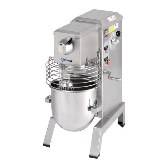
LIST OF ILLUSTRATIONS DESCRIPTION PAGE FIGURE 1 OVERALL VIEW OF MIXER..................III FIGURE 2 LUBRICATION DIAGRAM..................2.3 FIGURE 3 TRANSMISSION ASSEMBLY .................3.2 FIGURE 4 BEATER HEAD ASSEMBLY..................3.4 FIGURE 5 BEVEL GEAR DRIVE ASSEMBLY (STANDARD) ..........3.6 FIGURE 6 POWER TAKE-OFF ASSEMBLY (OPTIONAL) .............3.8 FIGURE 7 INPUT ASSEMBLY ....................3.10 FIGURE 8... - Page 4 OVERALL VIEW OF FOOD MIXER FIGURE 1 BOWL SUPPORT 10. LOWER MOUNTING BRACKET 11. UPPER MOUNTING BRACKET BOWL 12. SPEED CONTROL LEVER BOWL SUPPORT PIN 13. TIMER (OPTIONAL) BEATER HEAD SHAFT 14. SPEED INDICATOR LABEL INGREDIENT CHUTE 15. START PUSH-BUTTON (GREEN) SWING RING SAFETY GUARD 16.
-
Page 5: Trouble Shooting Guide
SRM12 TROUBLESHOOTING GUIDE TROUBLE POSSIBLE CAUSE REMEDY 1. Mixer will not operate. 1.1 Timer not turned on. 1.1 Turn timer on. 1.2 Burned switch contacts. 1.2 Replace. 1.3 Electrical service down. 1.3 Check electrical service. Replace fuse or reset circuit breaker if necessary. - Page 6 SRM12 TROUBLESHOOTING GUIDE (CONTINUED) 7. Attachments contact 7.1 Dented bowl. 7.1 Remove dents or replace bowl. side of bowl 7.2 Insufficient clearance 7.2 Adjust bowl height. between bottom of bowl and beater. 8. Excessive noise 8.1 Gears need to be repacked 8.1 Locate source by inspection...
-
Page 7: Mechanics Maintenance
MECHANICS MAINTENANCE Every six months a mechanic should perform the following inspection and maintenance. 1. BELT: a. WARNING: Start the mixer and adjust the speed control (Figure 1 [9]) to speed 4. Stop the mixer. FOR SAFETY, DISCONNECT THE ELECTRICAL POWER CORD. b. -
Page 8: Motor
MECHANICS MAINTENANCE 2. MOTOR: Check the motor (Figure 13 [6]) for overheating, noise and excessive end play of the shaft. Replace the motor if defective. 3. BOWL LIFT ADJUSTMENT: (Figure10) a. Place the 12 quart mixing bowl on the bowl support (Figure 1 [17]) and the 12 quart batter beater on the beater head shaft (Figure 1 [1]). -
Page 9: Lubrication
LUBRICATION The lubrication instructions are in Figure 2. The motor has pre-lubricated bearings with a service interval of ten years. The transmission and beater head gearing are packed with Nevastane 5P7 grease. They must be repacked every 500 working hours of the mixer. WARNING: NEVER WORK ON THE TRANSMISSION WITH THE MIXER RUNNING. -
Page 10: Removal Of Top Cover
MECHANICS MAINTENANCE REMOVAL OF TOP COVER a. The top cover (Figure 14 [9]) must be removed to perform maintenance operations on the mixer. It is secured by a spring clip at its front end and a screw in back. Before removing the top cover DISCONNECT THE ELECTRICAL POWER CORD. -
Page 11: Transmission
REPAIR INSTRUCTIONS TRANSMISSION: (Figure 3) REMOVAL: 1. WARING: DISCONNECT THE ELECTRICAL POWER SUPPLY CORD. 2. Remove the mixer top cover (Figure 14 [9]) per section 2, mechanics maintenance “REMOVAL OF TOP COVER” instructions on page 2.4 and remove the rear access panel. 3. - Page 12 Internal Gear Kit (Includes 5, 6, 12, 13) 1200440 Screw, Socket Head Cap 10-32 X 1 1012116 Gear, Internal 1012439A Magnet Kit (Includes 14, 15) 1012439 Magnet 1012438 Holder, Magnet 1012447A Transmission Wrap Assembly (Includes 16, 17) 1012447 Wrap, Transmission 4400503 Label, Univex Page 3.2...
- Page 13 Beater head assembly: (Figure 4) 1. Remove the 3/8-24 hex head cap screw, (left hand thread), and remove the beater head assembly using the two jack screws if necessary. 2. With tool T1201 remove the drive pin (Figure 4 [3]). 3.
-
Page 14: Beater Head Assembly
Beater Head Assembly Figure 4 Illus Part No Description 1000419A Beater Head Assembly (Includes All) 8800041 Beater Head Housing 1012107 Shaft, Beater Head 4400400 Pin, Drive 1/4 X 1 1200113 Key, Woodruff #9 1012167 Bearing, 6205LL 1012110 Spacer 1200118 Retaining Ring, Internal 1012114 Pinion Gear, Beater Head 1200120... - Page 15 BEVEL GEAR DRIVE ASSEMBLY WITHOUT POWER TAKE-OFF (STANDARD): (Figure5) 1. Remove the retaining ring (figure 5 [11]) from the end of the shaft and remove the spur gear [10] and key [12] from the shaft. 2. Remove the three 1/4-20 hex head cap screws [5 & 14]), Washers [3 & 4], deflector [2] and withdraw the bevel gear drive shaft assembly from the transmission housing.
- Page 16 Bevel Gear Drive Assembly (without PTO) Figure 5 Illus Part No Description 1012519 Bevel Gear Drive Assembly (Includes All) 1012446 Housing 1024417 Lubrication Deflector 1200075 Flat Washer 1/4 4400005 Lock Washer 1/4 1200022H Hex Hd Cap Screw 1/4-20 X 1 1030019 Bearing 1200117...
-
Page 17: Power Take-Off Assembly (Optional)
POWER TAKE-OFF ASSEMBLY (OPTIONAL): (Figure 6) 1. Remove the retaining ring (figure 6 [16]) from the end of the PTO shaft and remove the spur gear [15] and key [14] from the shaft. 2. Remove the three 1/4-20 hex head cap screws [9 & 18]), Washers [7 & 8], deflector [6] and withdraw the power take-off assembly from the transmission housing. - Page 18 Power Take-Off Assembly Figure 6 Illus Part No Description 1012518 Power Take-Off Assembly (Includes All) 8800033 Cover 8900019 Screw, Slotted Flat Head 4400210 Washer, PTO 8800012 Adaptor, PTO 4400030 Housing, PTO 1024417 Lubrication Deflector 1200075 Washer, Flat 1/4 4400005 Washer, Lock 1/4 1200022H Screw, Hex Hd Cap 1/4-20 X 1 1030019...
- Page 19 INPUT ASSEMBLY: (Figure 7) 1. Remove the retaining ring (Figure 7 [6]) and withdraw the input shaft assembly from the transmission housing. 2. Remove the retaining ring [1] and remove the bearing [2] from the input shaft assembly. 3. Remove one retaining ring [3], pinion gear [4] and woodruff key [7] from the input shaft assembly.
-
Page 20: Input Assembly
Input Assembly Figure 7 Illus Part No Description 1012520 Input Assembly (Includes All) 1200120 Retaining Ring, External 1012167 Bearing, 6203LL 1200119 Retaining Ring, External 1020010 Gear, Pinion 1030019 Bearing, 6204LL 1200117 Retaining Ring, Internal 1200113 Key, Woodruff #9 1012322 Shaft, Input 4400230 Key, Square 3/16 X 1-1/2 4400141... - Page 21 VERTICAL SHAFT ASSEMBLY: (Figure 8) 1. Remove the key (Figure 8 [4]) from the vertical shaft [2]. 2. Invert the transmission housing on a suitable support and press the vertical shaft assembly from the transmission housing. 3. Remove the pin [3] and press the bevel gear [1] from the vertical shaft assembly. bevel gear Page 3.11...
-
Page 22: Vertical Shaft Assembly
Vertical Shaft Assembly Figure 8 Illus Part No Description 1012521 Vertical Shaft Assembly (Includes All) 1012311 Gear, Bevel 1012434 Shaft, Vertical 4400022 Pin, Roll 5/16 X 1-1/2 1200113 Key, Woodruff #9 1030019 Bearing 1200117 Retaining Ring, Internal 8800042 Spacer Page 3.12... -
Page 23: Reassembly
TRANSMISSION REASSEMBLY: 1. Clean all components and inspect components for defects. Replace all assemblies found to be defective. NOTE: All gears should be replaced as sets. 2. If any shafts have become slightly scored during the disassembly process, polish the shafts with fine machinist’s crocus cloth. - Page 24 TRANSMISSION & SHAFTS ASSEMBLY FIGURE 9 Transmission Cover PTO Spur Gear Vertical Shaft Assembly Input Shaft Assembly Transmission Housing Assembly PTO Assembly Beater Head Assembly Page 3.14...
- Page 25 BOWL SUPPORT ASSEMBLY (Figure 10) 1. WARING: DISCONNECT THE ELECTRICAL POWER SUPPLY CORD. 2. Remove the mixer top cover (Figure 14 [9]) per section 2, mechanics maintenance “REMOVAL OF TOP COVER” instructions on page 2.4. 3. Remove the rear access panel (Figure 14 [11]). 4.
-
Page 26: Bowl Support Assembly
Bowl Support Assembly Figure 10 Illus Part No Description 1012432A Bowl Saddle Assembly (Includes 1 - 2) 1012432 Support, Bowl 4400219 Pin, Bowl Support 1012431A Slide Cover Assembly (Includes 3 - 4) 1012431 Cover, Movable Slide 4400278 Rubber Strip 1012430A Bowl Lift Frame Assembly (Includes 5 - 13) 1012430 Yoke... - Page 27 BOWL LIFT ASSEMBLY (Figure 11) 1. WARING: DISCONNECT THE ELECTRICAL POWER SUPPLY CORD. 2. Remove the mixer top cover (Figure 14 [9]) per section 2, mechanics maintenance “REMOVAL OF TOP COVER” instructions on page 2.4. 3. Remove the rear access panel (Figure 14 [11]). 4.
- Page 28 Bowl Lift Assembly Figure 8 Illus Part No Description 1012522 Bowl Lift Assembly (Includes All) 1012349A Bowl Lift Lever Assembly (Includes 1 - 2) 1012349 Lever, Bowl Lift 1012350 Collar, Bowl Lift 1012304A Bowl Lift Bearing Assembly (Includes 3 - 8) 1200301 Washer, Nylon 5/8 1012304...
- Page 29 SPEED CONTROL ASSEMBLY (Figure 12) DISASSEMBLY: 1. WARING: DISCONNECT THE ELECTRICAL POWER SUPPLY CORD. 2. Remove the mixer top cover (Figure 14 [9]) per section 2, mechanics maintenance “REMOVAL OF TOP COVER” instructions on page 2.4. 3. Remove the rear access panel (Figure 14 [11]). 4.
- Page 30 Speed Control Assembly Figure 12 Illus Part No Description 1012524 Speed Control Assembly (Includes All) 1012137A Speed Control Lever Assembly (Includes 1 - 4) 4400202 Knob, Speed Control 1020066 Lever, Speed Control 1012137 Hub, Speed Control 1200301 Washer, Nylon 5/8 X 1-1/8 1020068A Speed Control Housing Assembly (Includes 5 - 7) 1020068...
- Page 31 DRIVE ASSEMBLY (Figure 13) DISASSEMBLY: 1. WARING: DISCONNECT THE ELECTRICAL POWER SUPPLY CORD. 2. Remove the mixer top cover (Figure 14 [9]) per section 2, mechanics maintenance “REMOVAL OF TOP COVER” instructions on page 2.4. 3. Remove the rear access panel (Figure 14 [11]). 4.
- Page 32 Driven Pulley Belt Retainer Set Screws Connecting Rod Assembly Motor Mount Screws Contactor Motor Cord Connections Motor Cord Strap and Rail Vari-Speed Pulley Page 7.2...
- Page 33 Drive Assembly Figure 13 Illus Part No Description 1012346A Motor Slide Assembly (Includes 1 - 5, 20 - 22) 1012356 Rail, Motor Slide 1012346 Mount, Motor 1012355 Strap, Motor Slide 4400127 Washer, Flat 3/8 1200063 Nut, Kep 5/16-18 1012361 Motor, 1/3 HP, 115V, 60HZ, 1PH 6090012 Motor, 1/3 HP, 100/230V, 50/60HZ, 1PH 6090014...
- Page 34 DRIVE ASSEMBLY FIGURE 13 Page 7.4...
- Page 35 HOUSING ASSEMBLY FIGURE 14 ILLUS. No. PART No. DESCRIPTION QTY. 1012445 Housing, Mixer 1025710 Cap, Leg 1012435A Safety Ring Set (Includes 3 - 4) 1012435 Guard, Safety Ring, Right 1012436 Guard, Safety Ring, Left 1012443 Cover, Fixed Slide 1012423 Rail, Bowl lift 1012441A Safety Ring Bracket Set (Includes 7 - 10, 38) 4400413...
- Page 36 HOUSING ASSEMBLY FIGURE 14 DETAIL A SCALE 1 : 4 Page 8.2...
- Page 37 12 QUART MIXER CUTAWAY VIEW FIGURE 15 Page 9.1...
- Page 38 SCHEMATIC 115/208-240V, 60HZ, 1PH 220-240V 50/60HZ, 1PH FIGURE 16A POWER IN WIRING DIAGRAM L1 L2 GND SRM 12/20 100V, 50HZ, 1PH 220-240, 50HZ, 1PH 115/208-230V,60HZ, 1PH WIRING PACKAGE # 8800234 START SWITCH STOP SWITCH COLORED/PATTERNED WIRES ARE NOT FOR REFERENCE BUT FOR EASE OF USE OF THIS DIAGRAM RIGHT GUARD...
- Page 39 ELECTRICAL WIRING DIAGRAM 115V, 60HZ, 1PH / 220-240V, 50HZ, 1PH / 230V, 60HZ, 1PH 100V, 50/60HZ, 1PH FIGURE 2A POWER IN WIRING DIAGRAM L1 L2 GND SRM 12/20 220-240, 50HZ, 1PH (EUROPE ONLY) 115V, 60HZ, 1PH (CANADA ONLY) WIRING PACKAGE # 8800234 START SWITCH STOP...
- Page 40 ELECTRICAL WIRING DIAGRAM 380-400V, 50HZ, 3PH (FOR EUROPE ONLY) FIGURE 2C POWER IN WIRING DIAGRAM SRM 12/20 380-400V, 50HZ, 3PH (EUROPE ONLY) WIRING PACKAGE # 8800234 START SWITCH STOP SWITCH COLORED/PATTERNED WIRES ARE NOT FOR REFERENCE BUT FOR EASE OF USE OF THIS DIAGRAM RIGHT GUARD LEFT GUARD...
- Page 41 3 Old Rockingham Road, Salem, N.H. 03079-2140 Telephone -603-893-6191 Fax 1-603-893-1249 TOLL FREE ORDERING FAX 1-800-356-5614...
Need help?
Do you have a question about the SRM12 and is the answer not in the manual?
Questions and answers