Table of Contents
Advertisement
Quick Links
OPERATOR & PARTS
MANUAL
143390 v1.1
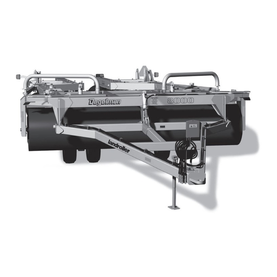
LANDROLLER 8000 FIVE-PLEX
D E G E L M A N
I N D U S T R I E S
L T D.
B O X
8 3 0 - 2 7 2
I N D U S T R I A L
D R I V E ,
LR8064 & LR8080
R E G I N A ,
S K ,
C A N A D A ,
S 4 P
3 B 1
F A X 3 0 6 . 5 4 3 . 2 1 4 0
P H 3 0 6 . 5 4 3 . 4 4 4 7
Serial Numbers 7220 and above
1 . 8 0 0 . 6 6 7 . 3 5 4 5
D E G E L M A N . C O M
Advertisement
Table of Contents

Related Manuals for Degelman LANDROLLER FIVE-PLEX 8000 Series


Summary of Contents for Degelman LANDROLLER FIVE-PLEX 8000 Series
- Page 1 OPERATOR & PARTS MANUAL 143390 v1.1 LANDROLLER 8000 FIVE-PLEX D E G E L M A N I N D U S T R I E S L T D. B O X 8 3 0 - 2 7 2 I N D U S T R I A L D R I V E , LR8064 &...
- Page 3 QUICK-START GUIDE WARRANTY LANDROLLER Five Plex REMEMBER! You must complete Product * Refer to operators manual for complete safety and operation info. Registration to be eligible for Warranty. ROLLER LIFT CIRCUIT....Connect Hydraulics Wheel Cylinders FRONT HITCH CIRCUIT....Front Hitch Cylinder SPREADER ARM CIRCUIT..
- Page 4 Moving Into Transport Position 1) Drive onto level ground. Ensure that the hitch pole 4) Slowly drive forward and wings should fall-back in line cylinder circuit is out of “fl oat” position. behind the center frame. 2) Fully extend the transport wheel cylinders to raise the rollers off ground and activate the hitch pole cylinder to allow installation of all fi ve (5) red transport bars.
-
Page 5: Table Of Contents
* Reference Sheet Quick-Start Guide OPERATORS SECTION - TABLE OF CONTENTS Introduction Safety Operation Pre-Operation Checklist Hook-Up / Floating Hitch System Transport to Field Position Field to Transport Position Service & Maintenance Maintenance Checklist and Specifications Repair - Hydraulic Cylinder Repair Repair - Wheel Hub Repair - Bearing Installation Decal Location Overview... -
Page 7: Introduction
Degelman rollers provide a smooth and level surface for faster, easier harvest operations and better seed-to-soil con- tact. -
Page 8: Safety
Safety Why is SAFETY important to YOU? 3 BIG Reasons: •Accidents Can Disable and Kill •Accidents Are Costly •Accidents Can Be Avoided SAFETY ALERT SYMBOL The Safety Alert Symbol means: he Safety Alert Symbol identifies important safety messages applied to the Landroller and in this ATTENTION! manual. - Page 9 GENERAL SAFETY YOU are responsible for the safe operation and 1. Read and understand the Operator’s maintenance of your Degelman Landroller. Manual and all safety signs before YOU must ensure that you and anyone else who operating, maintaining or adjusting is going to operate, maintain or work around the Landroller.
-
Page 10: Operation
Operation TO THE NEW OPERATOR OR OWNER OPERATING SAFETY The Degelman Landroller is designed to 1. Read and understand the Operator’s Manual and all safety signs before using. provide a smooth and level surface. 2. Stop tractor engine, set park brake, remove... -
Page 11: Pre-Operation Checklist
Operation BREAK-IN PRE-OPERATION CHECKLIST Although there are no operational restrictions on It is important for both personal safety and maintaining the Landroller when it is new, there are some checks good operational condition of the machine that the that should be done when using the machine for the pre-operational checklist be followed. -
Page 12: Hook-Up / Floating Hitch System
Operation HOOK-UP / UNHOOKING FLOATING HITCH SYSTEM FRONT HYDRAULIC CYLINDER CIRCUIT MUST BE The Landroller should always be parked on a level, SET TO FLOAT DURING FIELD OPERATION dry area that is free of debris and foreign objects. Follow this procedure to hook-up: The floating hitch system provides the Landroller with more flexibility while in the field position. -
Page 13: Transport To Field Position
Operation TRANSPORT TO FIELD POSITION 1. Drive the Landroller onto level ground so it is straight behind the tractor. 2. Activate the appropriate hydraulics to allow removal of all five (5) red transport bars. Place the transport bars onto the storage brackets provided and secure with lock-pin. -
Page 14: Field To Transport Position
Operation FIELD POSITION TO TRANSPORT 1. Drive onto level ground. Ensure that the hitch pole cylinder circuit is out of “float” position. 2. Fully extend the transport wheel cylinders to raise the rollers off ground and activate the hitch pole cylinder to allow installation of all five (5) red transport bars. - Page 15 Operation TRANSPORT SAFETY TRANSPORTING Use the following guidelines while transporting the 1. Read and understand ALL the information in the Landroller: Operator’s Manual regarding procedures and SAFETY when operating the Landroller in the 1. Use a safety chain. field/yard or on the road. 2.
-
Page 16: Service & Maintenance
Service & Maintenance MAINTENANCE SAFETY MAINTENANCE CHECKLIST 1. Review the Operator’s Manual and all safety Use the Maintenance Checklist provided for regular service intervals and keep a record of all scheduled items before working with, maintaining or operating the Landroller. maintenance: (Note: Do NOT grease the spherical bearings) 2. - Page 17 Service & Maintenance SERVICE STORAGE GREASING The Landroller should be carefully prepared for storage to ensure that all dirt, mud, debris and Grease: Use an SAE multipurpose grease with moisture has been removed. extreme pressure (EP) performance. Also acceptable is an SAE multipurpose lithium. Follow this procedure when preparing to store: 1.
- Page 18 Service & Maintenance HARDWARE SPECIFICATIONS HYDRAULIC SAFETY Note: Unless stated otherwise, hardware is typically: • Make sure that all components in the hydraulic Hex, Plated GR5 UNC or P8.8 (metric) system are kept in good condition and are clean. • Replace any worn, cut, abraded, fl attened or TORQUE SPECIFICATIONS crimped hoses and metal lines.
- Page 19 HYDRAULIC FITTING INSTALLATION Note: A DASH size refers to a diameter of a hose (inside) or of a tube (outside) measured in 1/16” increments. The following info is to help you identify and properly For example, a Hose specifi ed as dash 8 or -8 would install some of our standard hydraulic fi...
-
Page 20: Repair - Hydraulic Cylinder Repair
Service & Maintenance HYDRAULIC CYLINDER REPAIR REPAIRING A THREADED HEAD CYLINDER PREPARATION Set Screw Style When cylinder repair is required, clean off unit, Barrel Set Screw disconnect hoses and plug ports before removing Gland cylinder. When removed, open the cylinder ports and drain the cylinder's hydraulic fl... -
Page 21: Repair - Wheel Hub
Service & Maintenance WHEEL HUB REPAIR WHEEL NUT & WHEEL BOLT TORQUE TORQUE BOLT PATTERNS IMPORTANT Be sure DISASSEMBLY to block up unit securely before removing tires. 1. Remove dust cap. COMMON 2. Remove cotter pin from nut. HUB & SPINDLE 5 BOLT PATTERN 6 BOLT PATTERN 8 BOLT PATTERN... -
Page 22: Repair - Bearing Installation
Service & Maintenance SPHERICAL BEARING INSTALLATION SPHERICAL BEARING 117198 - Retaining Ring 117195 - Bearing Housing, c/w Retaining Rings COMPONENTS 117196 - Bearing 117197 - Bearing Adapter Sleeve, c/w Lock Nut and Lock Washer Lock Nut Lock Adapter Sleeve. Washer Snap Ring Bearing Snap Ring... -
Page 23: Decal Location Overview
6 142556 - Reflector, Red - 2 x 9 (4) 7 142650 - Reflector, Fluorescent - 2 x 9 (4) 8 143162- Decal, Read Operator’s Manual (1) 9 142008 - Decal, Degelman (5) 10 143055 - Decal, Landroller (2) 11 143054 - Decal, 8000 (1) -
Page 24: Troubleshooting
If problem stays contact your local Degelman dealer. Landroller rollers won’t turn. Material build-up around rollers. If it is only Ensure that there is no material build-up around rollers. -
Page 25: Hitch Frame Components
Hitch Frame Components (See Detail) 248330 - Hitch Frame Assembly (1) Front Hitch Components Detail 116302 - Safety Chain - 40,000 LB (1) 118615 - Flat washer, 1 x 3-1/8 x 1/4 (1) 118073 - Bolt, 1 x 3-1/2 (See Detail) UNC GR8 (1) 143111 - Hose Holder (1) -
Page 26: Center Frame Components
Center Frame Components 248320 - Centre Frame Assembly (1) (See Detail) Swing Arm Holder Components (See Detail) 142557 - Reflector, Amber - 2 x 9 (2) 142556 - Reflector, Red - 2 x 9 (2) (See Detail) 248165 - Swing Arm Assembly (2) 248345 - Centre Roller Assembly (1) 248160 - Swing... - Page 27 Center Frame Components Spreader Arm Component Detail 117087 - Bushing, 1-1/4 x 1 x 1 (2) 123092 - Cylinder, Monarch (2) (Refer to Cylinder Page for Detail) 118115 - Bolt, 1 x 6-1/2 (2) 118605 - Bolt, 5/8 x 1 UNC (2) 118508 - Lock washer, 5/8 (2) 248204 - Bushing (2) 118514 - Flat washer, 5/8 (2)
-
Page 28: Inner Wing Frame Components
Inner Wing Frame Components Inner Wing Frame Component Overview (See Cross Joint Detail) 248306 - Inner Wing Frame Assembly - 80 ft - LH (1) 248305 - Inner Wing Frame Assembly - 80 ft - RH (1) 248315 - Inner Wing Frame 248155 - Truss Arm Assembly - 64 ft - LH (1) Assembly (2) -
Page 29: Outer Wing Frame Components
Outer Wing Frame Components Outer Wing Frame Component Overview (See Light Details on Electrical 248318 - Outer Wing Frame Routing Page) Assembly - 64 ft - LH (1) 248317 - Outer Wing Frame 248311 - Outer Wing Frame Assembly - 64 ft - RH (1) Assembly - 80 ft - LH (1) 248310 - Outer Wing Frame Assembly - 80 ft - RH (1) -
Page 30: Hub & Spindle Components
Hubs & Spindles 131324 - Hub/Spindle Assembly (4) Center Frame Wheels 131700 - Hub CTD 618 - c/w Cups (1) 131701 - Hub Cap - CTD618 (1) 118835 - Cotter Pin 131322 - Spindle S618 - c/w Nut (1) 3/16 x 1-1/2 (1) 131026 - Dust Seal - CR#20140 (1) 131022 - Bearing Cone #25580 (1) 131023 - Bearing Cup #25520 (1) -
Page 31: Hydraulic Cylinders
Hydraulic Cylinders ROCKSHAFT / SPREADER ARM CYLINDERS 123092 - Cylinder - 3-1/2 x 16 x 1-1/2, Monarch Rockshaft and Swing Arm Cylinders 123087 - Seal Kit (1) Requires: 118930 - Pin, 1 x 2-13/16 (2) 118924 - Flat Washer .59 ID x .9 OD (2) 118796 - Shoulder Bolt, 1/2 GR8 UNC (2) REAR TRANSPORT WHEEL CYLINDERS Requires:... -
Page 32: Hydraulic Hose Holder Locations
Hydraulic Hose Holder Locations Double Stack Hose Clamp 118945 - Bolt, 5/16 x 2-3/4 780279 - Top Plate (1) 780278 - Hose Clamp-2 Halves 780278 - Hose Clamp-2 Halves Single Hose Clamp Note: 80’ Model shown. 64’ Model 118144 - Bolt, 5/16 x 1-1/2 has two less clamp locations in this area. -
Page 33: Hydraulic Routing - Wheels Cylinders
Hydraulic Routing - Wheel Cylinders 141581 - Coupler, Tip - 3/4 ORB (2) 141515 - Nipple, 3/4 JIC M x 3/4 ORB M (2) 126550 - Hose, 3/8 x 75 (2) 141501 - Tee, 3/4 JIC MxMxM (2) 123092 - Rockshaft 126676 - Hose, 126583 - Hose, 3/8 x 44 (2) Cylinder, Monarch (2) -
Page 34: Hydraulic Routing - Front Hitch Cylinder
Hydraulic Routing - Front Hitch Cylinder Float Valve Detail 126552 - Hose, 3/8 x 144 (1) 248368 - Float Valve Bracket (1) 118718 - Locknut, 126645 - Hose, 3/8 x 138 (1) 141581 - Coupler, Tip - 3/4 ORB (2) 5/16 (2) 141515 - Nipple, 3/4 JIC M x 3/4 ORB M (2) 248385 - Plug, 3/4 ORB m (1) -
Page 35: Hydraulic Routing - Spreader Arm Cylinders
Hydraulic Routing - Spreader Arm Cylinders 141581 - Coupler, Tip - 3/4 ORB (2) 141515 - Nipple, 3/4 JIC m x 3/4 ORB m (2) 126662 - Hose, 3/8 x 390 (2) Fitting Overview 141505 - Tee, 3/4 JIC m x 3/4 JIC m x 123092 - Spreader Arm 3/4 ORB m (1) Cylinders, Monarch (2) -
Page 36: Electrical Layout & Light Components
Electrical Wiring 4-WIRE ROUTING OVERVIEW Wire Harness - 4 Wire, w/plugs (1) 244615 - Wire Harness, LR8000-64’ 244616 - Wire Harness, LR8000-80’ 129045 - Hose Tie, 1/8 x 8 Light Wiring Cable runs along side the hydraulic hoses and is secured in place with hose ties. -
Page 37: Warranty
Re-torque of fastening hardware, Hydraulic fluid purities, drive train alignments, and clutch operation) 3. If parts not made or supplied by Degelman have been used in the connection with the unit, if, in the sole judgement of Degelman such use affects its performance, safety, stability or reliability. - Page 38 It is the retail customer’s responsibility to deliver the product to the authorized Degelman dealer, from whom he purchased it, for service or replacement of defective parts, which are covered by warranty. Repairs to be submitted for warranty consideration must be made within forty-five days of failure.
Need help?
Do you have a question about the LANDROLLER FIVE-PLEX 8000 Series and is the answer not in the manual?
Questions and answers