Table of Contents
Advertisement
D E G E L M A N
I N D U S T R I E S
B O X
8 3 0 - 2 7 2
I N D U S T R I A L
R E G I N A ,
S K ,
C A N A D A ,
F A X 3 0 6 . 5 4 3 . 2 1 4 0
P H 3 0 6 . 5 4 3 . 4 4 4 7
1 . 8 0 0 . 6 6 7 . 3 5 4 5
D E G E L M A N . C O M
L T D.
D R I V E ,
S 4 P
3 B 1
OPERATOR & PARTS
LR7634, LR7640, LR7645, LR7651
MANUAL
142630 v1.5
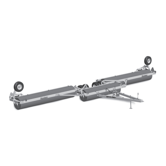
TRI-PLEX
LANDROLLER
Advertisement
Table of Contents

Related Manuals for Degelman Tri-Plex Landroller 7634


Summary of Contents for Degelman Tri-Plex Landroller 7634
- Page 1 OPERATOR & PARTS MANUAL 142630 v1.5 TRI-PLEX D E G E L M A N I N D U S T R I E S L T D. B O X 8 3 0 - 2 7 2 I N D U S T R I A L D R I V E , LANDROLLER R E G I N A ,...
-
Page 3: Table Of Contents
TABLE OF CONTENTS - OPERATORS SECTION Introduction Safety Operation Transport to Field Position Field to Transport Position Service & Maintenance Service / Maintenance Checklist Repair - Hydraulic Cylinder Repair - Autofold Cable Tension Repair - Wheel Hub Repair - Bearing Installation Troubleshooting PARTS SECTION Hitch Frame Components... -
Page 5: Introduction
Degelman rollers provide a smooth and level surface for faster, easier harvest operations and better seed-to-soil contact. -
Page 6: Safety
Safety Why is SAFETY important to YOU? 3 BIG Reasons: •Accidents Can Disable and Kill •Accidents Are Costly •Accidents Can Be Avoided SAFETY ALERT SYMBOL The Safety Alert Symbol means: he Safety Alert Symbol identifies important safety messages applied to the Landroller and in this ATTENTION! manual. - Page 7 GENERAL SAFETY YOU are responsible for the safe operation and 1. Read and understand the Operator’s maintenance of your Degelman Landroller. Manual and all safety signs before YOU must ensure that you and anyone else who operating, maintaining or adjusting is going to operate, maintain or work around the Landroller.
-
Page 8: Operation
Operation TO THE NEW OPERATOR OR OWNER OPERATING SAFETY The Degelman Landroller is designed to 1. Read and understand the Operator’s Manual and all safety signs before using. provide a smooth and level surface. 2. Stop tractor engine, set park brake, remove... - Page 9 Operation BREAK-IN PRE-OPERATION CHECKLIST Although there are no operational restrictions on It is important for both personal safety and the Landroller when it is new, there are some checks maintaining good operational condition of the that should be done when using the machine for the machine that the pre-operational checklist be first time, follow this procedure: followed.
- Page 10 Operation HOOK-UP / UNHOOKING TRANSPORT SAFETY The Landroller should always be parked on a level, 1. Read and understand ALL the information in the Operator’s Manual regarding procedures dry area that is free of debris and foreign objects. and SAFETY when operating the Landroller in Follow this procedure to hook-up: the field/yard or on the road.
-
Page 11: Transport To Field Position
Operation TRANSPORT TO FIELD POSITION 6. Lift the drums off the ground. 1. Drive the landroller onto level ground so it is 7. Slowly back-up the landroller straight behind the tractor. spreading the wings until they are almost fully in field position. 2. -
Page 12: Field To Transport Position
Operation FIELD TO TRANSPORT POSITION 1. On level ground, extend cylinders to fully lift 5. Fully extend lift cylinders raising the drums off the rollers off ground. (This will tighten autofold ground. cables and open the “Swing Arm” latches.) 2. Drive forward until roller wing trail behind. 6. -
Page 13: Service & Maintenance
Service & Maintenance MAINTENANCE SAFETY HYDRAULIC SAFETY 1. Review the Operator’s Manual and all safety 1. Always place all tractor hydraulic controls in items before working with, maintaining or neutral before dismounting. operating the Landroller. 2. Make sure that all components in the hydraulic 2. - Page 14 Service & Maintenance TORQUE SPECIFICATIONS HARDWARE/HOSE SPECIFICATIONS CHECKING BOLT TORQUE Unless otherwise stated: • Hardware - Hex, Plated GR5 UNC or P8.8 (metric) The tables shown below give correct torque values • Hydraulic Hoses - 3/8 & 1/2, ends come with for various bolts and capscrews.
-
Page 15: Service / Maintenance Checklist
Annually 142492 - Decal, Patent - Bent Axle (2) • Bolt tightness 142455 - Decal, Endwheel Positioning (2) 142008 - Decal, Degelman (3) • Wheel bearings 142594 - Decal, Landroller - 7634 (2) or • Latch mechanism 142463 - Decal, Landroller - 7640 (2) or 142571 - Decal, Landroller - 7645 (2) or •... -
Page 16: Repair - Hydraulic Cylinder
Service & Maintenance HYDRAULIC CYLINDER REPAIR 5. Take the plastic removal ring from the seal kit: PREPARATION Types of Cylinders a) Straighten the ring and remove any kinks or When cylinder repair (Wire Ring / Threaded Head) excessive curl to make installation easier and is required, clean off prevent it from falling out. - Page 17 Service & Maintenance 8. Remove locknut, piston and head from rod. 11. b) Tighten the band clamp to ensure the wire ring is fully seated. Then, loosen the clamp Piston Seal (2pcs) approx. 1/2 a turn to allow band clamp to slide Wear Ring during fi nal assembly.
- Page 18 Service & Maintenance REPAIRING A THREADED HEAD CYLINDER REPAIRING A THREADED HEAD CYLINDER Set Screw Style Locking Ring Style Barrel Barrel Set Screw Locking Gland Ring Lock Piston U-Cup Wear Dual Seal Seal Piston Ring O-Rings Seal Wiper Piston Seals Seal (Style may vary, Lock...
-
Page 19: Repair - Autofold Cable Tension
Service & Maintenance TIRE SAFETY AUTOFOLD LATCH ADJUSTMENT 1. Failure to follow proper procedures when mounting a tire on a wheel or rim can produce a blow out which may result in serious injury or death. 2. Do not attempt to mount a tire unless you have Autofold Latch the proper equipment and experience to do the... -
Page 20: Repair - Wheel Hub
Service & Maintenance WHEEL HUB REPAIR COMMON HUB & SPINDLE COMPONENTS Dust Inner Inner Flat Seal Cone Spindle Washer Outer Outer Slotted Dust Cone Nut & Cotter Pin IMPORTANT Be sure to block up unit securely before removing tires. DISASSEMBLY ASSEMBLY 1. -
Page 21: Repair - Bearing Installation
Service & Maintenance SPHERICAL BEARING INSTALLATION - Previous Bearing Model SPHERICAL BEARING 117198 - Retaining Ring 117195 - Bearing Housing, c/w Retaining Rings COMPONENTS 117196 - Bearing 117197 - Bearing Adapter Sleeve, c/w Lock Nut and Lock Washer Lock Nut Lock Adapter Sleeve. -
Page 22: Troubleshooting
If problem stays contact your local Degelman dealer. Landroller rollers won’t turn. Material build-up around rollers. If it is only Ensure that there is no material build-up around rollers. -
Page 23: Hitch Frame Components
Hitch Frame Components Front Hitch Components Detail Hitch Pole Assembly 244702 - LR7634 (2) 143111 - Hose 243668 - LR7640 (2) Holder (1) 244700 - LR7645 (2) 118026 - Bolt, 5/8 244701 - LR7651 (2) x 2 UNC (1) 118514 - Flat washer, 5/8 (1) 118508 - Lock washer, 5/8 (1) 118407 - Nut, 5/8 UNC (1) -
Page 24: Center Section Components
Center Frame Components Center Frame Exploded 123700 - Center Frame 244870 - Center Frame Cylinder, Monarch (2) Assembly (1) (Previous)122728 -Center Frame Cylinder (2) 118420 - Lock Nut 1/2 (2) 117110 - Bushing, 243717 - Collar, Autofold (2) 243500 - Lock Pin, 1-1/4 x 3/4 (2) 118082 - Bolt, 1/2 5/16 x 2-1/2 (2) -
Page 25: Swing Arm & Cross Joint Components
Swing Arm & Cross Joint Components Swing Arm Holder Detail 243748 - Swing Arm 142008 - Decal, Holder (2) Degelman (1) 118026 - Bolt, 5/8 x 2 (8) 118537 - Flat Washer, 5/8 - F436 (16) 118508 - Lock Washer, 5/8 (8) -
Page 26: Wing Frame Components
Wing Frame Components Wing Frame Overview Wing Frame Assembly 244852 - LR7634 - RH (1) 244856 - LR7640 - RH (1) 244851 - LR7634 - LH (1) 244857 - LR7640 - LH (1) 244861 - LR7645 - RH (shown) (1) 244862 - LR7645 - LH (opposite) (1) 244980 - LR7651 - RH (1) Wing Roller Assembly... -
Page 27: Endwheel Components
Endwheel Components Endwheel Components Detail 123700 - Cylinder, Monarch (2) 243996 - Transport Lock - Monarch, 17-5/16 (2) (Previous)122728 - (Previous) 243990 - Transport Lock, 16-3/4 (2) Endwheel Cylinder (2) 243500 - Lock Pin, 5/16 x 2-1/2 (2) 244314 - Link Plate Assembly, Upper (2) 117110 - 117087 - Bushing (2) -
Page 28: Hubs & Spindles, Cylinders
Hubs, Spindles & Cylinders 131324 - Hub/Spindle Assembly (4) 131700 - Hub CTD 618 - c/w Cups (1) Center Frame Wheels Replacement Stud: 131708 - Bolt Stud, 9/16 x 2-1/4 UNF 131701 - Hub Cap - CTD618 (1) 118835 - Cotter Pin 131322 - Spindle S618 - c/w Nut (1) 3/16 x 1-1/2 (1) 131026 - Dust Seal - CR#20140 (1) -
Page 29: Hydraulic & Electrical Routing
Hydraulic & Electrical Routing 4-Wire Harness - w/plugs (1) Light Brackets & Components 244598 - LR7634/40 118402 - Nut, 1/4 (2) - or - 141581 - Coupler, Tip - 3/4 ORB (2) 118533 - Lock Washer, 1/4 (2) 244599 - LR7645/51 141515 - Nipple, 3/4 JIC M x 3/4 ORB M (2) 142135 - SMV Sign (1) - Page 30 Hydraulic & Electrical Routing - Previous Previous Light Brackets Wire Harness - w/plugs (1) & Components 244593 - LR7634/40/45 - or - 118402 - Nut, 1/4 (2) 141581 - Coupler, Tip - 3/4 ORB (2) 244594 - LR7651 118533 - Lock Washer, 1/4 (2) 141515 - Nipple, 3/4 JIC M x 3/4 ORB M (2) 142135 - SMV Sign (1)
-
Page 31: Warranty
Re-torque of fastening hardware, Hydraulic fluid purities, drive train alignments, and clutch operation) 3. If parts not made or supplied by Degelman have been used in the connection with the unit, if, in the sole judgement of Degelman such use affects its performance, safety, stability or reliability. -
Page 32: B O X
It is the retail customer’s responsibility to deliver the product to the authorized Degelman dealer, from whom he purchased it, for service or replacement of defective parts, which are covered by warranty. Repairs to be submitted for warranty consideration must be made within forty-five days of failure.
Need help?
Do you have a question about the Tri-Plex Landroller 7634 and is the answer not in the manual?
Questions and answers