
Related Manuals for GFA ELEKTROMATEN TS 971


Summary of Contents for GFA ELEKTROMATEN TS 971
- Page 1 Installation instructions Door control TS 971 51171521 a 02.2012 Status: 22.02.2012...
- Page 2 GfA - Gesellschaft für Antriebstechnik GmbH Wiesenstraße 81 D-40549 Düsseldorf www.gfa-elektromaten.de info@gfa-elektromaten.de...
-
Page 3: Table Of Contents
Contents General safety information .................... 6 Technical data ......................7 Mechanical installation ....................8 Electrical installation ..................... 9 Connection cable connection overview ................10 Carrying out the electrical installation ................11 Mains connection ......................12 Mains connection to control .................... 12 Completing the electrical installation ................ - Page 4 Menu .......................... 23 Operating mode ......................23 Door positions ......................... 24 Door functions ......................... 25 Safety functions ....................... 28 DU / FU settings ......................29 Advanced door functions ....................30 Maintenance cycle counter ....................31 Readout of information memory ..................32 Deletion of all settings .....................
- Page 5 Reversing time change ....................51 Maintenance cycle counter ..................... 52 Short-circuit/overload display ..................52 Display for active "WSD" wireless safety device ............. 52 Standby function ......................53 Lighting of the internal push buttons ................53 11 Status display ......................54 12 Explanation of symbols ....................
-
Page 6: General Safety Information
1 General safety information Specified normal use The door control is intended for a power-operated door with drive unit. Safe operation is only guaranteed with specified normal use. No liability for damage by other applications or non-observance of the instructions. Modifications are only permitted with the agreement of the manufacturer. -
Page 7: Technical Data
Type of relay contacts (2 pcs) contacts V AC Loading of relay contacts, ohmic/inductive Control power consumption Operation: -5..+40 Temperature range C° Storage: +0..+50 to 93 % Air humidity non-condensing Protection class of housing IP65 Compatible GfA limit switch NES; DES... -
Page 8: Mechanical Installation
3 Mechanical installation Control installation! • Only use in suitable environments • Mount on a level surface free of vibration • Only mount in the vertical position • Install in a position in the vicinity of and clear view of the door and where the operator is not in a hazardous position themselves Requirements Mount on a solid surface using adequate fixings to ensure a safe and reliable fixing. -
Page 9: Electrical Installation
4 Electrical installation Warning - Danger to life from electric shock! • Disconnect and lock-off the Mains Supply • Observe the applicable regulations and standards • Ensure that all electrical connections are correctly terminated and all terminal screws are adequately tightened •... -
Page 10: Connection Cable Connection Overview
Connection cable connection overview DES and NES DES connection cable limit switch motor connection cable X13 Motor connector X12 Limit switch plug Pin Core Term. Pin Core Term. Phase W 5/wh +24 V safety circuit Phase V 6/bn Channel B (RS485) Phase U 7/gn Ground... -
Page 11: Carrying Out The Electrical Installation
Carrying out the electrical installation ▶ Remove covers. ▶ Open cable entry ① or ②. ▶ Insert and connect motor/limit connection cable in the open cable entry ① (from the bottom) or ② (from the top). ▶ Properly tighten cable glands. Caution - Damage of components! •... -
Page 12: Mains Connection
Mains connection 3-phase 3-phase 1-phase 1-phase with neutral without neutral symmetrical asymmetrical conductor conductor Mains connection to control Completing the electrical installation Connect any other control devices and/or safety equipment. Install and tighten cable entries and/or cable glands. For initial operation, leave the control enclosure covers open. -
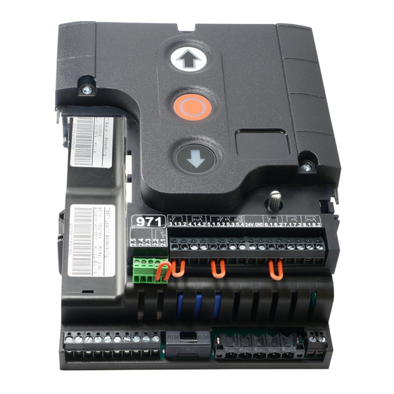
Page 13: Overview Of Control
Overview of control DES/ F1 = 1,5A t Ant. 24 V supply voltage, external devices DES/ DES or NES limit switch socket Power mains supply Micro-fuse 1.5 A time lag Safety edge system and Door safety switch Motor socket Selector switch Emergency stop button Open button Automatic closing On/Off... -
Page 14: Starting Up The Control
5 Starting up the control ▶ Plug-in or switch on the mains supply line DES: Rapid adjustment of limits 1. Check rotating direction 2. Move to final limit position open 3. Save limit position 4. Move to final limit position close 5. -
Page 15: Nes: Fast Adjustment Of Limit Switches
Read the drive unit installation instructions! • Adjusting the cam limit switch, see drive unit installation instructions NES: Fast adjustment of limit switches 1. Check rotating direction 2. Move to final limit position open and adjust limit switch S3 OPEN 3. -
Page 16: Electrical Installation - Control Accessories
6 Electrical installation – Control Accessories X1 Ex ter nal Stop X3 Emergenc y Stop X4 Automatic cl osing On / Off X1 External supply X3 Emergency stop X4 Automatic closing On/Off External device A2 Control device A3 Control device Emergency stop Key-switch X5 Contr ol unit... -
Page 17: X6 Photo Cell
X6 Photo cell X6 Photo cell 1 2 3 4 5 1 2 3 4 5 A8 Reflective Through Through photo cell photo cell photo cell A9 Transmitter A11 Transmitter A10 Receiver A12 Receiver X6 Li ght c urtai n X6 Light curtain 24V* 24V*... -
Page 18: Connection Of Safety Edge System And Door Safety Switch
Connecti on of s afety edge sy stem and door s afety switc h Spiral cable connection Electrical safety edge system Junction box Voltage supply Door safety switch input Electrical safety edge system input Electrical safety edge system End of line resistor 8k2 Door control socket Pneumatic safety edge system Junction box... -
Page 19: Wsd" Wireless Safety Device
"WSD" wireless s afety devic e "WSD" Wireless Safety Device Open "WSD" door module ⑥ "WSD" door module ST2 System 2 connection cable socket ① ⑦ Door module button Safety edge evaluation switch: ② Switch "A" System 1, "B" System 2 Optical (set upper position <... -
Page 20: Optical Safety Edge System, System 2 On "Wsd" Door Module
Optic al s afety edge system, Sy stem 2 on "W SD" door module Optical safety edge system, System 2 on "WSD" door module A23 WSD door module A24 System 2 end box Door safety switc h on "WSD" door module Door safety switch on "WSD"... -
Page 21: Teaching-In Of "Wsd" Door Module
Teachi ng-i n of "W SD" door module Teach-in the "WSD" door module Insert battery Insert or switch on mains supply line Activate Teaching "WSD" door module found, right point lights statically Note! • Use of a safety edge system only possible via menu "0.1", door operating mode "3", "4"... -
Page 22: Control Programming
7 Control programming 1. Programming can only be accessed after rapid adjustment of limit switches! 2. Select menu and confirm 3.a) Set and save functions 3.b) Set and save positions 4. Exit programming... -
Page 23: Menu
8 Menu Operati ng mode Operating mode Door operating mode OPEN Hold-to-run CLOSE Hold-to-run OPEN Self-hold CLOSE Hold-to-run OPEN Self-hold CLOSE Self-hold OPEN Self-hold CLOSE Self-hold, Photo beam or Safety Edge Fault - CLOSE hold-to-run release via X5: external push button OPEN Hold-to-run CLOSE... -
Page 24: Door Positions
Door positions Door positions OPEN limit switch coarse adjustment OPEN/CLOSE door movement CLOSE limit switch coarse adjustment OPEN/CLOSE door movement OPEN limit switch fine adjustment Without door movement, [ + ] correct in OPEN [ – ] correct in CLOSE CLOSE limit switch fine adjustment Without door movement, [ + ]... -
Page 25: Door Functions
Door functi ons Door functions part 1 Safety device Spiral cable Teach-in "WSD" door module wireless safety device Safety edge function in the pre-limit area Safety edge system active Safety edge system inactive Ground adjustment (DES) Reversing upwards in the overrun area (DES) Overrun correction (DES) - Page 26 Door functions part 2 automatic closing 0 to 240 seconds Advanced photo cell function Override automatic closing time and immediate CLOSE command Vehicle recognition Override automatic closing time and immediate CLOSE command if photo cell is obstructed > 1.5 seconds Maximum number of consecutive safety edge Stop-and-return operations (See page 38)
- Page 27 Door functions part 3 Relay function on X20 Set or adjust operating position via menu 1.7 (DES only) Relay function on X21 Set or adjust operating position via menu 1.8 (DES only) Pulse signal for 1 second Permanent signal Red lamp, permanent light during door movement OPEN 3 seconds flashing CLOSE...
-
Page 28: Safety Functions
Door functions part 4 Intermediate open function All command inputs active Input X7.2 and internal radio receiver active Input X5.4 and OPEN push button active Safety functions Safety functions Force monitoring (DES) 0 = Off Adjustable from 2 % to 10 % overload Photo cell ignore function Teach the control to ignore a position where the photo beam is obstructed every time the door closes i.e. -
Page 29: Du / Fu Settings
DU / FU settings DU/FI settings OPEN output speed Output speed in rpm CLOSE output speed Output speed in rpm Increased CLOSE output speed To opening height 2.5 m Output speed in rpm 0 = Off Changeover position to CLOSE output speed (observe minimum 2.5 m opening height!) OPEN/CLOSE door movement OPEN acceleration... -
Page 30: Advanced Door Functions
Adv anced door functi ons Advanced door functions Selection of manufacturer of radio transmitters Internal radio receiver deactivated Tedsen Teleco "COD1" Guthrie Douglas, Teleco "COD2", JCM, Dickert Radio function Memorise a radio transmitter Deletion of a radio transmitter Deletion of all radio transmitters... -
Page 31: Maintenance Cycle Counter
Maintenanc e cy cle counter Maintenance cycle counter Counter adjustment 01-99 corresponds to 1,000 to 99,000 cycles Cycles are counted down Reaction on reaching zero "CS" display with set value of maintenance cycle Changeover to hold-to-run and "CS" display with set value of maintenance cycle Changeover to hold-to-run and "CS"... -
Page 32: Readout Of Information Memory
Readout of i nformati on memory Readout memory Cycle counter value 7-digit number Cycle counter in divisions of ten consecutively 1,000,000 10,000 100,000 1,000 Last Fault Displays the last 6 faults consecutively Cycle counter value of the last programming change 7-digit Cycle counter in divisions of ten consecutively 1,000,000... -
Page 33: Safety Devices
9 Safety devices X2: Door safety switch The door safety switch is installed on the door and connected to the door control via the spiral cable. Menu "3.4": Function type Reaction upon activation Switch contact open: Door stops "1" Slack-wire / pedestrian door Switch contact closed: Door ready for operation Switch contact open: Door stops Switching contact closed: Changeover to hold-to-run mode... - Page 34 The magnetic contacts in the switch are switched by a permanent magnet. The door control assesses the switching status of the contacts independently of each other. F1.7 is displayed if there is a fault. Crash switch as NC or NO contact The crash door switch is activated if the door is pushed out of the guides.
-
Page 35: X2: Safety Edge System
X2: Safety edge system The door control automatically detects three different safety edge systems. If no safety edge system is detected fault “F2.0” is displayed. Important! • Safety Edge Systems must comply with BS EN 12978! 1K2 resistor evaluation This safety device is intended for a pneumatic switch with NC contact in series with a resistor of 1K2, +/-5 %, 0.25 W. -
Page 36: Installation Of The Spiral Cable
Optical safety edge system The functional principle is based on a thru-beam photo cell fitted into the leading edge rubber strip. The light beam is interrupted by compressing the rubber edge. Fault “F2.9” is displayed if the safety edge beam is interrupted or faulty. Installation of the spiral cable The spiral cable should enter the door control panel from the left or right hand side and must enter through and be firmly held in place with a cable gland. - Page 37 Note: Ground adjustment! • Automatic compensation for cable stretch or change of ground of approx. 2-5 cm • With DES limit switch only • Do not use with overrun correction • Do not use with pneumatic switch Note: Stop and re-open in the pre-limit area! •...
- Page 38 Maximum number of consecutive safety edge Stop-and-return operations Parameter "2.5": If the safety edge is operated on consecutive timed to close, “2.3”, cycles this is the maximum number of times that the door will attempt to close. If the set value is exceeded, automatic closing is deactivated and fault "F2.2"...
-
Page 39: Integrated "Wsd" Wireless Safety Device
Integrated "WSD" wireless safety device For evaluating the safety edge system and/or door safety switch without spiral cable. For initial operation, see "Teach-in of the WSD door module". Usable safety devices 8K2 resistor evaluation Safety edge systems Optical safety edge system (low-power sensors only) Slack-wire/pedestrian door switch Door safety switch Crash switch with NC contact... -
Page 40: Functional Description
10 Functional description X: 24 V DC voltage supply Connection of external devices such as photo cell, radio receiver, relay, etc. via the 24 V and GND terminals. Caution - Damage of components! • Total current consumption of external devices: maximum 350 mA X1: Control mains supply line and external supply Control mains supply line Connection via terminals X1/1.1 to X1/1.4 and PE... -
Page 41: X4: Automatic Closing Off/On
X4: Automatic closing Off/On Connect a key switch, time clock or similar to terminals X4/1 and X4/2 to turn off and on the time delay to close function ”2.3”. (N/O – time to close ON, N/C – time to close OFF). X5: Control device Warning! •... -
Page 42: X6: Through / Reflective Photo Cell Or Light Curtain
X6: Through / Reflective photo cell or Light curtain Photo cell A photo cell is used for presence detection. It is only active in door operating mode "3" and "4", in the OPEN limit position or during the closing operation. If the photo cell is interrupted, fault indication "F2.1"... - Page 43 Effect of obstructing the photo cell Door position Effect of obstructing the photo cell CLOSE limit position No function Upwards travel No function OPEN limit position No function Without automatic closing OPEN limit position With automatic closing delay Reset automatic closing timer “2.3”...
- Page 44 Photo cell ignore function Parameter "3.2": Function Photo cell function disabled "0" "1" Set parameter “3.2” = 1 and then exit programming to activate the “photo cell ignore” teach-in mode. Warning! • Presence detection “stop and re-open” is disabled in the Teach-in mode In the Teach-in mode, the door must be fully opened and closed twice.
-
Page 45: X7: Pull Switch/Radio Receiver
X7: Pull switch/radio receiver Connection of a pull switch or external radio receiver via terminals X7/1 and X7/2. Must be Volt free, clean contact free (NO). Ceiling pull switch or radio receiver function Parameter "2.6": Pulse type Reaction upon activation The Door CLOSES from the open limit position, or "1"... -
Page 46: Internal Radio Receiver
Internal radio receiver If the integrated radio receiver is fitted, select parameter "7.6" to set the type, manufacturer, of the radio transmitters. Parameter “7.7” Memorise or delete radio transmitter codes. Note! • Combination of manufacturer of radio transmitters possible • Only use 433 MHz radio transmitter •... -
Page 47: Deleting An Individual Handheld Transmitter
Deleti ng an i ndividual handhel d tr ans mitter Deleting an individual radio transmitter 1. Activate delete, 10 seconds active 2. Delete 3. Switch to door operation Deleti ng all handhel d tr ans mitters Deleting all radio transmitters 1. -
Page 48: X8: Intermediate Open On/Off
X8: Intermediate open On/Off Connect a key switch to terminals X8/1 and X8/2 to switch the intermediate open on and off (N/O full open, N/C intermediate (part) open). Set the intermediate open position via parameter “1.6”. When an Open command is given the door opens to the selected position. Time delay to close will start when the door reaches the selected position. -
Page 49: X20 / X21: Potential Free Relay Contacts
X20 / X21: Potential free relay contacts The relay functions are set by parameters "2.7" or "2.8". Caution - Damage of components! • Maximum current at 230 V AC 1 A and at 24 V DC 0.4 A • We recommend the use of LED lamps •... -
Page 50: Run Time Monitoring (Nes Only)
After the parameter is set or adjusted the door must carry out a complete opening and closing operation in self-hold. The force monitoring is a self-learning system which is effective from 5 cm up to approx. 2 m. Slow progressive changes, e.g. reduction of the spring torsion, are compensated for automatically. -
Page 51: Ubs System
UBS system The UBS system is a simple pluggable connection technology from GfA. The control devices are connected to the control by a commercially available patch cable and detected automatically. Note! • The UBS devices function in the same way as wired control devices... -
Page 52: Maintenance Cycle Counter
Maintenance cycle counter Parameter "8.5": A maintenance cycle can be set between "0" and "99,000" cycles, the adjustment is made in steps of one thousand. The maintenance cycle counter reduces by one each time the Open limit position is reached. When the cycle counter reaches zero the settings in Parameter “8.6”... -
Page 53: Standby Function
Standby function If there is no fault or command pending, the control switches the display to "Standby". Standby is active if the automatic closing is than 60 seconds. Only the left point, or with active "WSD" both points, is/are displayed. The display switches out of Standby when a new command, open or close are received or by activation the "S"... -
Page 54: Status Display
11 Status display Errors Display: "F" and code Status Description Measures to solve the problem code Terminals X2.1 – X2.2 open. Check door safety switch. Slack-wire/pedestrian contact open. Check the connection cable is proper fitted. DES safety circuit open. Check emergency manual operation. Emergency manual operation activated. - Page 55 Errors Display: "F" and code Status Description Measures to solve the problem code 8k2 safety edge system activated. Check the safety edge system is functioning. (Contact strip) Check the connection cable for short-circuit. 8k2 safety edge system defective. Check the safety edge system is functioning. (Contact strip) Check the connection cable is in order.
- Page 56 Errors Display: "F" and code Status Description Measures to solve the problem code No limit switch detected Connect the limit switch to the control. (active at initial start-up). Check the limit switch connection cable. Limit switch system has been changed without Reset the control via reset of the control.
- Page 57 Errors Display: "F" and code Status Description Measures to solve the problem code Switch control off and on. RAM error. Replace control if necessary. Switch control off and on. Internal control error. Replace control if necessary. Check DES connector and connection cable. Digital limit switch error (DES).
- Page 58 Errors Display: "F" and code Status Error description Measures for fault correction code Check mains input voltage. Excess voltage in the DC voltage link. Error acknowledgement by command. Change acceleration/deceleration times/speeds. Drive unit overload. Temperature limit exceeded. Cool down the drive unit and reduce number of cycles.
- Page 59 Commands Display: "E" and code Code Command description An open command is present. Inputs X5.3, X7.2, internal radio system, UBS command or UBS radio receiver. A stop command is present. Inputs X5.2, X7.2, internal radio system, UBS command or UBS radio receiver or simultaneous open and close command.
- Page 60 Status indications Status Description display Preset value for maintenance cycle counter status reached. Left point does not light: Control circuit short-circuit or overloaded. Right point lights: "WSD" internal wireless safety device active. Change of rotating direction activated, only possible at initial start-up and FI-drive unit. Change of rotating direction carried out, only possible at initial start-up and FI-drive unit.
-
Page 61: Explanation Of Symbols
12 Explanation of symbols Symbol Explanation Prompt: Read installation instructions Prompt: Check Prompt: Note Prompt: Note the setting of the program below Default adjustment of the program Default adjustment of the program, value on the right Default adjustment of the minimum limit, dependent on drive unit Default adjustment of the maximum limit, dependent on drive unit Setting range Prompt: Select program or value,... - Page 62 Symbol Explanation Prompt: Setting via OPEN/CLOSE built in push button, open push button: Value upwards; CLOSE button: Value downwards Prompt: Press stop button once via built in push button Prompt: Save, press stop button once via built in push button Prompt: Save, press stop button for three seconds via built in push button Prompt: Reset the control,...
-
Page 63: Declaration Of Incorporation/Declaration Of Conformity
D eclar ati on of Inc orporati on/Declar ation of Confor mity Declaration of Incorporation pursuant to Machinery Directive 2006/42/EG for a partly completed machine Appendix II Part B GfA - Gesellschaft für Antriebstechnik Dr.-Ing Hammann GmbH & Co KG Declaration of Conformity Wiesenstraße 81 40549 Düsseldorf...
Need help?
Do you have a question about the ELEKTROMATEN TS 971 and is the answer not in the manual?
Questions and answers