Table of Contents
Advertisement
EN
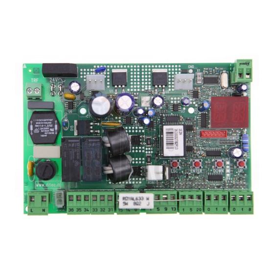
Installation manual for control panel for 2-motor 24V automations with built-in radio.
Power unit
BATK1
DITEC S.p.A.
Via Mons. Banfi, 3 - 21042 Caronno Pertusella (VA) - ITALY
Tel. +39 02 963911 - Fax +39 02 9650314
www.ditec.it - ditec@ditecva.com
24V
TRF
F1
L N
36 35 34
33 32 31 15 14 0
BAT
24V=
24V=
Motor2
Motor1
L N
Power supply
IP1967EN
E2H
rev. 2012-07-31
AUX
Memory
card
COM
ESC
ENTER
DOWN
JR1
1 5 9 13
1 5 20 0 1 6 0 1 8
ANT
JR5
GOL4
POWER
UP
Advertisement
Table of Contents

Related Manuals for DITEC Entrematic HomeLink E2H


Summary of Contents for DITEC Entrematic HomeLink E2H
- Page 1 1 5 20 0 1 6 0 1 8 24V= 24V= Motor2 Motor1 Power supply DITEC S.p.A. Via Mons. Banfi, 3 - 21042 Caronno Pertusella (VA) - ITALY Tel. +39 02 963911 - Fax +39 02 9650314 www.ditec.it - ditec@ditecva.com...
-
Page 2: Table Of Contents
INDEX Subject Page General safety precautions EC declaration of conformity Technical data 3.1 Applications Connection of power supply Commands 5.1 SOFA1-SOFA2 or GOPAVRS self-controlled safety edge Outputs and accessories Selection Signals Adjustments 9.1 Switching on and off 9.2 Key combination 9.3 Main menù... -
Page 3: General Safety Precautions
GENERAL SAFETY PRECAUTIONS This installation manual is intended for professionally competent personnel only. The installation, the power connections and the settings must be completed in conformity with Good materials (plastic, polystyrene, etc.) should not be discarded in the environment or left within reach of children, as these are a potential source of hazard. -
Page 4: Ec Declaration Of Conformity
Degree of protection IP55 IP54 Memorizable radio codes 200 [BIXMR2] 200 [BIXMR2] Radio frequency 433,92 MHz 433,92 MHz NOTE: the given operating and performance features can only be guaranteed with the use of DITEC accessories and safety devices. 3.1 Applications... -
Page 5: Connection Of Power Supply
CONNECTION OF POWER SUPPLY An omnipolar disconnection switch with minimum contact gaps of 3 mm must be included in the mains supply. suitable overcurrent cutout. Use a H05RN-F 3G1,5 or H05RR-F 3G1,5 type electric cable and connect to the terminals L (brown), N (blue), (yellow/green) in the automation. -
Page 6: Commands
COMMANDS Command Function Description 5 N.O. STEP BY STEP Selecting , the closure of the contact activates a closing or opening operation in the sequence: open-stop-close-open. Warning: if automatic closing is enabled, the duration of the stop is selected via the selection OPENING Selecting , the closure of the contact... -
Page 7: Sofa1-Sofa2 Or Gopavrs Self-Controlled Safety Edge
SOFA1-SOFA2 or GOPAVRS self-controlled safety edge Command Function Description SAFETY TEST Insert the electronic card SOFA1-SOFA2 or GOPAVRS in the SOFA1-SOFA2 housing AUX on the control panel. GOPAVRS Selecting , the terminal 41 activates a safety edge test before each operation. If the test fails, an alarm message is visualised on the display. -
Page 8: Outputs And Accessories
OUTPUT AND ACCESSORIES Output Value - Accessories Description Power supply output for external accessories, including automation status lamp. Electronically protected output. 24 V / 0,5 A Automation status lamp (proportional). The light switches off when the automation is closed; the light switches 24 V / 3 W frequency while the automation is operating. -
Page 9: Selection
SELECTION Description Display mode setting. Visualization mode. It is Maintenance mode. It is only possible to visualize possible to visualize and the values and parameters modify the values and pa- present. rameters present. The entry in maintenance mode is indicated by the permanent switching on of the right- hand point. -
Page 10: Adjustments
ADJUSTMENT NOTE: before making all the automation adjustments, insert the dedicated memory module and press , or load the con guration applying to the automation installed see options . When the power is connected or in the case of motor non-selection, the display will block all operations and give error message. - Page 11 9.3 Main menu to select the required function Display Description The menu allows to visualise and modify the main settings of the control panel. BA - Basic Adjustments. The menu allows to visualise and modify the main adjustments of the control panel. RO - Radio Operations.
- Page 12 to select the required function The procedures to activate the functions are described in the table. Display Description AC - enabling of automatic closing : disabled C5 - step-by-step/opening command operation : step-by-step RM - remote control operation : step-by-step AM - AUX coupling board operation : step-by-step SS - selection automation status at start up...
- Page 13 9.5 Second level menu - BC (Basic Configurations) to select the required function Display Description When enabled (ON), with every power supply connection opening and closing end stops and/or the stop limit switches during opening and closing operation at the speed set with the adjustment During the learning operation, the display visualizes the message...
- Page 14 Display Description NI - Activation of NIO electronic anti-freeze system. even in low temperatures. Note: for correct operation, the control panel must be expo- sed to the same ambient temperature as the motors. 64 - Functioning of safety stop/closing command. STOP CLOSING P2 - Functioning of partial opening command contact 1-20.
- Page 15 9.6 Second level menu - BA (Basic Adjustments) to select the required function WARNING: the gap between the adjustment values of the parameters may vary according to the type of automation. Display Description MT - Selection of automation type. NO - None O3 - OBBI-ARC F3 - FACIL NONE...
- Page 16 Display Description FC - Selection of closing limit switch mode. NO - None RA - Deceleration limit switch (after the activation, the door wing slows down its movement) NONE DECELERATION SX - Stop limit switch (after the activation, the door wing stops its movement) PX - Proximity limit switc (after the activation, the door wing continues as far as STOP...
- Page 17 Display Description TR - Setting motor 1 closing delay time. [s] Adjustment, in seconds, of the delay time for starting the manoeuvre of motor 1, in relation to motor 2. TO - Impostazione tempo di ritardo motore 2 in apertura. [s] Regolazione in secondi del tempo di ritardo della partenza di manovra del motore 2 rispetto al motore 1.
- Page 18 Display Description Adjustment, in seconds, of the lead time for the switch-on from a voluntary command. Adjustment, in seconds, of the lead time for the switch-on from a voluntary command. WARNING: it is possible that, owing to the type of automation and control panel, certain menus are not available.
- Page 19 9.7 Second level menu - RO (Radio Operations) to select the required function The procedures to activate the functions are described in the table. Display Description SR - Transmitter memory storage..x2, x3... It is possible to directly access the Transmitter memory storage menu with the display switched off, but only with Display visualization mode set at 00 or 03: - by transmitting a remote control not present in the memory, - by transmitting an unstored channel of a remote control already present in the me-...
- Page 20 Display Description NONE OPENING NO - None 1-3 - Opening command 1-4 - Closing command 1-5 - Step-by-step command CLOSING STEP-BY-STEP P3 - Partial opening command LG - Courtesy light status change command 1-9 - STOP command PARTIAL COURTESY WARNING: 1-3 (opening) and 1-5 (step-by-step) are LIGHT binary options and are dependent by the selection.
- Page 21 9.8 Second level menu - SF (Special Functions) to select the required function The procedures to activate the functions are described in the table. Display Description SP - Setting the password (EXAMPLE) Note: this is only possible when the password is not set. The setting of the password prevents unauthorised personnel from accessing selections and adjustments.
- Page 22 Display Description (EXAMPLE) available in the memory positions as follows: : OBBI : FACIL : LUXO : ARC parameters (type of automation, operation speed, operation times and deceleration ti- mes). NOTE: the control panel automatically saves the last con guration set, and keeps it memorised in the storage module.
- Page 23 9.9 Second level menu - CC (Cycles Counter) to select the required function The procedures to activate the functions are described in the table. Display Description CV - View total manoeuvres counter. = 241.625 manoeuvres (example) Note: view only. CA - Setting the maintenance alarm interval. (max 500.000 partial manoeuvres) = 08 08 50 00 = 85.000 manoeuvres (ex) (EXAMPLE) = 50...
- Page 24 9.10 Second level menu - AP (Advanced Parameters) to select the required function WARNING: the gap between the adjustment values of the parameters may vary according to the type of automation. Given the complexity of the parameters, use of the Advanced Parameters menu is recommended only Display Description AA - Activating advanced parameters menu.
- Page 25 Display Description TP - Setting of automatic closing time after partial opening. Adjustment occurs with intervals of varying sensitivity. - from 0 to 59 sec with 1 sec intervals; 0 SECONDS 59 SECONDS - from 1 to 2 min with 10 sec intervals. 1 MINUTE 2 MINUTES PO - Approaching/deceleration speed during opening.
- Page 26 Display Description SM - Selection of the operating mode of photocell terminals 1-6. (only with 00 - During manoeuvre, the opening of the safety contact stops movement with disengagement. 01 - During manoeuvre, the opening of the safety contact STOP + STOP + stops movement with disengagement.
-
Page 27: Display Viewing Mode
10. DISPLAY VIEWING MODE WARNING: it is possible that, owing to the type of automation and control panel, certain menus are not available. 10.1 Automation status display Warning: the automation status display mode is visible only with the Display viewing mode set on 02. Display Description Automation closed. - Page 28 1-6 - Safety with opening and closing stop. 1-8 - Safety with closing reversal. 1-9 - STOP command. P3 - Partial opening command. 3P - Hold-to-run opening command. 4P - Hold-to-run closing command. CX - AUX coupling board command reception. F1 - Generic limit switch relating to motor 1.
-
Page 29: Alarms And Anomalies Display
10.3 Alarms and anomalies display WARNING: alarms and anomalies are displayed when any display selection is made. The signaling of Type of Display Description Remedy alarm M0 - Automation type not selected. If the dedicated memory module is present press Select a type of automation. - Page 30 Type of Display Description Remedy alarm A0 - Failure of test of safety sensor on con- tact 6. correctly. If the supplementary SOF card is not in- A3 - Failure of test of safety sensor on con- tact 8. correctly. If the supplementary SOF card is not in- A7 - Incorrect connection of contact 9 to Connect the 1-9 contact...
- Page 31 STARTING WARNING: the system must have mechanical doorstops of appropriate strength or limit switches must be installed. WARNING: if this control panel is being used to replace a faulty one, it is possible to reset the last automation con guration by inserting the storage module of the old control panel in the housing on the new one, then loading the last con guration set with the command.
-
Page 32: Radio Receiver Operation
12. RADIO RECEIVER OPERATION Ricevitore / Receiver 10 s The control panel is equipped with a radio receiver with a frequency of 433.92 MHz. The antenna consists of a rigid wire, 173 mm long, connected to the ANT clamp. the tuned BIXAL antenna. NOTE: to connect the external antenna to the control panel, use a coaxial cable type RG58 max 10 m . -
Page 33: Example Application Of Automation With Two Swinging Door Wings
EXAMPLE APPLICATION OF AUTOMATION WITH TWO SWINGING DOOR WINGS When the E2H control panel is used in applications for double 36 35 34 33 32 31 wings automations with overlap- lowing connections. 24V= 24V= Motor 2 Motor 1 (Fig. 13.1) Installation with mechanical doorstops in opening and closing phases, without the use of elec- tric limit switches. - Page 34 EXAMPLE APPLICATIONS FOR AUTOMATION WITH ONE SWINGING DOOR WING When the E2H control panel is used in applications for single wing 33 32 31 the following connections. 24V= Motor 1 (Fig. 14.1) Installation with mechanical doorstops in opening and closing phases, without the use of elec- tric limit switches.
- Page 36 DITEC ESPAÑA ARENYS DE MAR Tel. +34 937958399 Fax +34 937959026 www.ditecespana.com DITEC FRANCE MASSY Tel. +33 1 64532860 Fax +33 1 64532861 www.ditecfrance.com DITEC GOLD PORTA ERMESINDE-PORTUGAL Tel. +351 22 9773520 Fax +351 22 9773528/38 www.goldporta.com DITEC SWITZERLAND BALERNA Tel. +41 848 558855 Fax +41 91 6466127 www.ditecswiss.ch...
Need help?
Do you have a question about the Entrematic HomeLink E2H and is the answer not in the manual?
Questions and answers