Table of Contents
Advertisement
Advertisement
Table of Contents

Related Manuals for Eliwell IDPlus 961


Summary of Contents for Eliwell IDPlus 961
- Page 1 PLUS 961 - 971 - 974 Electronic controllers for refrigerating units...
-
Page 3: Table Of Contents
CONTENTS USER INTERFACE........KEYS AND LED ........ACCESSING AND USING MENUS . BASIC COMMANDS MENU ..... BASIC COMMANDS EDIT LOCK..PROGRAMMING MENU....COPY CARD..........PASSWORD..........ENABLING DEFROST CYCLE MANUALLY ..........DIAGNOSTICS......... ALARMS............. 10 MAX AND MIN TEMPERATURE ALARM............11 MECHANICAL ASSEMBLY....12 ELECTRICAL WIRING...... -
Page 4: User Interface
ENGLISH Electronic controllers for refrigerating units * To activate the LOC function: - enter the ‘Basic Commands’ menu by pressing - press the keys within 2 seconds. If the LOC function is active and you try to enter the ‘Parameters’ menu, the word LOC appears. If this happens, the parameters are still displayed but cannot be edited. -
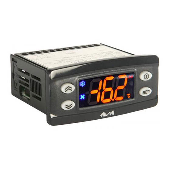
Page 5: Keys And Led
KEYS AND LEDs Reduced Set/Economy LED Press and release Flashing: Reduced set active Scrolls through menu items Increases values Press for at least 5 secs Compressor LED Activates the Manual Defrost function Permanently on: Compressor Active Flashing: Delay, protection or blocked start-up. -
Page 6: Accessing And Using Menus
ACCESSING AND USING THE MENUS Resources are organised into menus which are accessed by briefly tapping the key (‘Basic Commands’ menu) or by keeping the key pressed for more than 5 seconds (‘Programming’ menu). Either do not press any keys for 15 seconds (time-out) or press the key once, to confirm the last value displayed and return to the previous screen. -
Page 7: Basic Commands Edit Lock
BASIC COMMANDS EDIT LOCK It is possible to disable the keypad on this device. The keypad can be locked by entering the ‘Basic Commands’ menu using and pressing within 2 seconds or by programming the ‘LOC’ parameter (see ‘diS’ label folder) With the keypad locked you can still access the ‘Basic Commands’... -
Page 8: Copy Card
USING THE COPY CARD The Copy Card is an accessory connected to the TTL serial port used for quick programming of the device parameters (upload and download a parameter map to one or more devices of the same type). Upload (label UL) and copy card formatting (label Fr) operations should be performed as explained below: The ‘FPr’... -
Page 9: Password
PASSWORDS The password ‘PA1’ allows access to the programming parameters. In the standard configuration the password is disabled (value = 0). To enable it (value ≠ 0) and assign the required value, enter the ‘Programming’ menu, in the folder with the ‘diS’... -
Page 10: Alarms
ALARMS Label Fault Cause Eff ects Remedy • Display label E1 • measured values are outside • Alarm icon permanently on • check probe type NTC/PTC (H00) Probe 1 faulty operating range • Min/max alarm regulator disabled • check the probe wiring (cold room) •... -
Page 11: Max And Min Temperature Alarm
MAX AND MIN TEMPERATURE ALARM Relative Temperature Value Absolute Temperature Value to setpoint (Att=1) (Att=0) Setpoint LAL - AFd LAL + AFd Setpoint - LAL Setpoint + HAL Setpoint - LAL + AFd Setpoint + HAL - AFd Minimum temperature Temp. -
Page 12: Mechanical Assembly
MECHANICAL ASSEMBLY The instrument is designed for panel mounting. Make a hole of 29x71 mm, insert the instrument and fix it using the brackets provided. Do not mount the instrument in humid and/or dirty places; it is suitable for use in ordinary polluted places. -
Page 13: Conditions Of Use
LIABILITY AND RESIDUAL RISKS ELIWELL CONTROLS SRL shall not be liable for any damages deriving from: - installation/use other than that prescribed and, in particular, that which does not comply with safety standards anticipated by regulations and/or those given herein;... -
Page 14: Disclaimer
DISCLAIMER This manual and its contents remain the sole property of ELIWELL CONTROLS SRL, and shall not be reproduced or distributed without authorization. Although great care has been exercised in the preparation of this document, ELIWELL CONTROLS SRL, its employees or its vendors, cannot accept any liability whatsoever connected with its use. - Page 15 This device complies with standard EN 13485 as follows: - suitable for storage - climate range A - measurement class 1 in the range from -35°C to 25°C (*) (* exclusively using Eliwell NTC probes) Voluntary marks/certifications: ENEC/UL (check on the device label). Classification: operating (not safety) device for integration.
-
Page 16: Parameters Table
TABLE OF PARAMETERS PAR. DESCRIPTION Temperature SEtpoint. COMPRESSOR REGULATOR (folder with “CP” label) diFferential. Relay compressor tripping differential. The compressor stops on reaching the Setpoint value (as indicated by the adjustment probe), and restarts at temperature value equal to the Setpoint plus the value of the differential. - Page 17 defrost interval time. Interval between the start of two successive defrosting operations. defrost Counting type. Selection of count mode for the defrosting interval. 0 = compressor operating hours (DIGIFROST® method); Defrosting active only if compressor is on. 1 = Real Time - equipment operating hours; defrost counting is always active when the machine is on and start everytime the instrument switch on, 2 = compressor stop.
- Page 18 ALARMS (folder with “AL” label) Allow you to select if the parameters HAL and LAL will have absolute (Att=0) or relative (Att=1) value. Alarm Fan differential. Alarm differential. Higher ALarm. Maximum temperature alarm. Temperature value (in relative value) which if exceeded in an upward direction triggers the activation of the alarm signal.
- Page 19 CONFIGURATION (folder with "CnF" label) H00 (!) Probe type selection, PTC or NTC (Default). 0 = PTC; 1 = NTC. Stand-by operating mode. 0 = display switch off; 1 = display switch off, loads and alarms stopped; 2 = display with OFF label, loads and alarms stopped. Configurability digital inputs/polarity.
- Page 20 Parameters - Default Setting PAR. ID961 ID971 ID974 U.M. RANGE DEFAULT RANGE DEFAULT RANGE DEFAULT -50,0 ... 99,0 -50,0 ... 99,0 -50,0 ... 99,0 °C/°F +0,1 ... +30,0 +0,1 ... +30,0 +0,1 ... +30,0 °C/°F LSE ... +302 99,0 LSE ... +302 99,0 LSE ...
- Page 21 PAR. ID961 ID971 ID974 U.M. RANGE DEFAULT RANGE DEFAULT RANGE DEFAULT 0 ... 10 0 ... 10 0 ... 10 hours 0 ... 999 0 ... 999 0 ... 999 0 ... 10 0 ... 10 0 ... 10 hours 0 ...
- Page 22 C C O O N N N N E E C C T T I I O O N N S S / / C C O O N N N N E E S S S S I I O O N N I I / / C C O O N N E E X X I I O O N N E E S S / / A A N N S S C C H H L L U U S S S S - - P P L L A A N N / / C C O O N N N N E E X X I I O O N N S S / / ПОДКЛЮЧЕНИЕ ID961 ID971 ID961...
- Page 23 TECHNICAL DATA (DATI TECNICI) Mechanical Caracteristics (Caratteristiche Meccaniche) Front protection (Protezione frontale): IP65. Housing (Contenitore): PC+ABS UL94 V-0 resin plastic casing, polycarbonate glass, thermoplastic resin keys Dimensions (Dimensioni): front 74x32 mm, depth 59 mm. (excluding terminals) Mounting (Montaggio): panel mounting with 71x29 mm (+0.2/-0.1 mm) drilling template. Terminals (Morsetti): screw terminal for cable with a diameter of 2,5mm Serial (Seriale):...
- Page 24 ID 961 electronic controllers for refrigerating units USER INTERFACE MACHINE STATUS MENU word is enabled, you will see it at the To access the “Machine Status” menu entrance of the “Programming” menu. The user has a display and four keys for Press and quickly release the “set”...
- Page 25 DIAGNOSTICS TECHNICAL DATA eration equipment and has been tested with regard to the aspects concerning The alarm condition is always signalled by European reference standards on safety. It Frontal panel protection: IP65. the buzzer (if present) and by the led of is classified as follows: Casing: plastic body in resin type the alarm icon...
- Page 26 Tab. 1 Parameter Table DESCRIPTION RANGE DEFAULT VALUE* LEVEL** U.M. PAR. COMPRESSOR REGULATOR (folder with “CP” label) diFferential. Relay compressor tripping differential. The compressor stops on reaching the 0.1...30.0 °C/°F Setpoint value (as indicated by the adjustment probe), and restarts at temperature value equal to the Setpoint plus the value of the differential.
- Page 27 Wiring diagram TERMINALS 1 - 2 N.C. compressor relay ID 961 - 12 V 1 - 3 N.A. compressor relay 6 - 7 Power supply 8 - 10 Probe 1 input (thermostat) TTL input for Copy Card NOTE: Default user settings 1 2 3 6 7 8 9 ID 961 - 230 V...
Need help?
Do you have a question about the IDPlus 961 and is the answer not in the manual?
Questions and answers