HIKVISION DS-KH6320-WTE1 Installation Manual
Network indoor station
Hide thumbs
Also See for DS-KH6320-WTE1:
- Installation & quick start manual (15 pages) ,
- Configuration manual (82 pages) ,
- Operation manual (35 pages)
Advertisement
Advertisement

Related Manuals for HIKVISION DS-KH6320-WTE1


Summary of Contents for HIKVISION DS-KH6320-WTE1
- Page 1 Network Indoor Station Installation Guide...
- Page 2 Network Indoor Station Installation Guide Symbol Conventions The symbols that may be found in this document are defined as follows. Symbol Description Indicates a hazardous situation which, if not avoided, will or Danger could result in death or serious injury. Indicates a potentially hazardous situation which, if not Caution avoided, could result in equipment damage, data loss,...
-
Page 3: Table Of Contents
Network Indoor Station Installation Guide Contents 1 Appearance ....................1 2 Terminal and Wiring Description ..............3 2.1 Terminal Description ..................3 2.2 Wiring Description .................... 3 3 Installation ....................5 3.1 Wall Mounting Plate ..................5 3.2 Wall Mounting with Junction Box ..............5 A. -
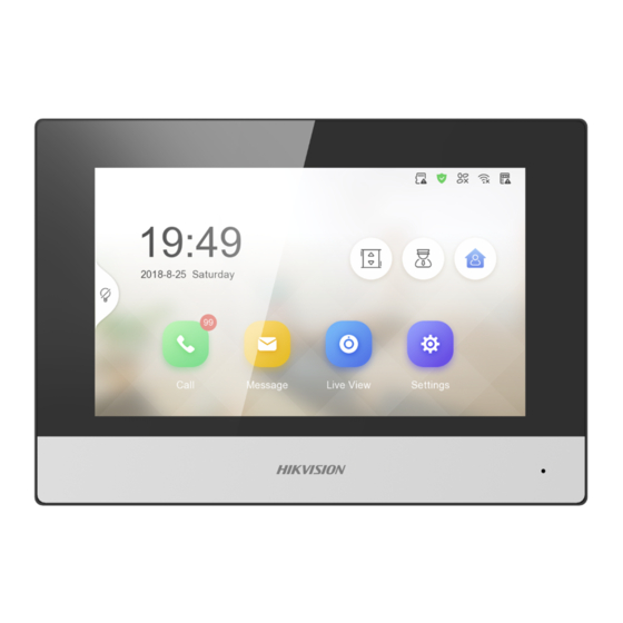
Page 4: Appearance
Network Indoor Station Installation Guide 1 Appearance Front Panel Figure 1-1 Front Panel Table 1-1 Description Description Display Screen Microphone... - Page 5 Network Indoor Station Installation Guide Rear Panel Figure 1-2 Rear Panel Table 1-2 Description Description Debugging Port Network Interface Loudspeaker TF Card Slot Alarm Terminal Reserved Network Interface and Power Supply Note The debugging port is used for debugging only.
-
Page 6: Terminal And Wiring Description
Network Indoor Station Installation Guide 2 Terminal and Wiring Description 2.1 Terminal Description There are 20 pins in the terminal on the rear panel of the indoor station: 2 RS-485 pins, 5 reserved pins, 4 relay output pins, 8 alarm input pins, and 1 GND pin. Figure 2-1 Terminal Description 2.2 Wiring Description Wire the devices with power supply cables as picture shown below. - Page 7 Network Indoor Station Installation Guide Figure 2-2 Wiring Description...
-
Page 8: Installation
Network Indoor Station Installation Guide 3 Installation Indoor station supports wall mounting. 3.1 Wall Mounting Plate The wall mounting plate and the junction box are required to install the indoor station onto the wall. The dimension of junction box should be 75 mm (width) × 75 mm (length) × 50 mm (depth). - Page 9 Network Indoor Station Installation Guide Before You Start Note Make sure the device in the package is in good condition and all the assembly • parts are included. The power supply the indoor station supports is 12 VDC. Please make sure your •...
-
Page 10: Cables
Network Indoor Station Installation Guide A. Cables Table A-1 Wiring Cables Routing Path Twisted Pair : Twisted Pair : Twisted Pair : Parallel Cable : 24AWG 20AWG 18AWG ≥ 24AWG (0.22 (0.2mm²) (0.5mm²) (0.8mm²) mm²) DS-KAD706 - Transmission Transmission Transmission Transmission DS-KAD706-S Distance ≤... - Page 11 UD13572B...
Need help?
Do you have a question about the DS-KH6320-WTE1 and is the answer not in the manual?
Questions and answers