Nellcor OXIMAX N-600X Series Service Manual
Pulse oximeter with alarm management system
Hide thumbs
Also See for OXIMAX N-600X Series:
- Service manual (188 pages) ,
- Operator's manual (212 pages)

Related Manuals for Nellcor OXIMAX N-600X Series


Summary of Contents for Nellcor OXIMAX N-600X Series
- Page 1 N-600 Pulse Oximeter with Alarm Management System Service Manual To Purchase, Visit Avobus.com or call 1-800-674-3655...
- Page 2 To obtain information about a warranty, if any, contact Nellcor’s Technical Services Department at 1.800.635.5267 or your local Nellcor representative. Purchase of this instrument confers no express or implied license under any Nellcor Puritan Bennett patent to use the instrument with any sensor that is not manufactured or licensed by Nellcor Puritan Bennett LLC...
-
Page 3: Table Of Contents
Table of Contents Chapter 1. Safety Information ............... 9 Overview......................9 Warnings ......................9 Cautions ......................11 Chapter 2. General Introduction ............13 Overview.......................13 Related Documents .................13 Oximeter Description and Intended Use............13 Description....................13 Intended Use ...................14 List of Components..................15 Front Panel ....................16 User Interface..................16 Oximeter Visual Indicators ..............17 Monitoring Values ..................19 Audible Indicators...................20... - Page 4 Product Standards for Compliance ............32 Product Safety Standards ................32 Electromagnetic Compatibility (EMC) Standards ........32 Manufacturer’s Declaration ................32 Basics ......................32 Electromagnetic Compatibility (EMC)...........33 Electromagnetic Immunity ..............33 Sensor and Cable Compliance ..............35 Safety Tests....................36 Ground Integrity ..................36 Leakage Current..................37 Chapter 4. Theory of Operations ............39 Overview.......................39 Understanding Pulse Oximetry ..............39 Theoretical Principles ................39...
- Page 5 Chapter 7. Operating the Oximeter............. 55 Overview.......................55 Monitoring Oximeter Power .................55 Battery Fuel Gauge .................55 Low Battery Indicator ................56 Powering the Oximeter .................57 Power Prerequisites.................57 Power-On Self-Test (POST) ..............57 Automatic Shutdown and Power Off............59 Using OxiMax™ Pulse Oximetry Sensors ...........59 Sensor Detection ..................60 Sensor Detection Failure.................61 Managing the Oximeter Backlight..............61...
- Page 6 Patient Conditions...................98 OxiMax™ Pulse Oximetry Sensor Performance Considerations ....98 Safety Information ..................98 Inaccurate Sensor Measurement Conditions...........99 Signal Loss....................99 Recommended Usage ................99 Chapter 10. Oximeter Preventive Maintenance ........101 Overview.....................101 Cleaning ......................101 Periodic Safety Checks ................101 Chapter 11. Modifying and Testing the Oximeter ....... 103 Overview.....................103 Setting Institutional Defaults (Sample)............103 Performance Verification................105...
- Page 7 Obtaining Technical Assistance..............159 Returning your Oximeter ................159 Chapter 13. Ordering Oximeter Spare Parts ........161 Overview.....................161 Ordering Replacement Parts ...............161 Spare Parts List ...................162 Chapter 14. Repairing the Oximeter ..........165 Overview.....................165 Fuse Replacement ..................166 Oximeter Disassembly and Reassembly.............167 Disassembling the Oximeter ..............167 Reassembling the Oximeter ..............169 Battery Replacement...................170 Removing the Old Battery ..............170...
- Page 8 10030881 Rev. B 12-2008 viii Service Manual...
-
Page 9: Chapter 1. Safety Information
WARNING Only qualified service personnel should open the oximeter housing, remove and replace components, or make adjustments. If your medical facility does not have a qualified service technician, please contact Nellcor’s Technical Services or your local Nellcor representative. WARNING Before attempting to open or disassemble the oximeter, disconnect the power cord to avoid possible injury. - Page 10 The OxiMax pulse oximetry sensor extrapolates from the date and time provided by the Nellcor OxiMax N-600x pulse oximeter when recording the sensor event record to the sensor. The accuracy of the date/time is determined by the date/time setting of the pulse oximeter.
-
Page 11: Cautions
Cautions WARNING When installing the pulse oximeter’s AC power cord, ensure the cord is carefully positioned to prevent tripping and entanglement. Cautions Caution Observe standard ESD (electrostatic discharge) precautions when disassembling, reassembling, and when handling any of the components of the oximeter. Caution When installing the OxiMax N-600x pulse oximeter power supply or the Main Board PCB, tighten the seven screws (4-in lbs. - Page 12 Safety Information 10030881 Rev. B 12-2008 Service Manual...
-
Page 13: Chapter 2. General Introduction
Before attaching any of the various Nellcor approved OxiMax pulse oximetry sensors to the oximeter, refer to the individual Directions for Use (DFU) and the OxiMax Sensor Accuracy Grid (SAG) The N-600x Operator’s and N-600x Service Manuals are posted on the Internet at:... -
Page 14: Intended Use
General Introduction proper firmware, activation of the pulse oximeter’s OxiMax SPD™ Alert (SPD) feature is possible. Intended Use The OxiMax N-600x pulse oximeter is intended for prescription use only with neonatal, pediatric, and adult patients who are well or poorly perfused in hospitals, hospital-type facilities, intra-hospital transport, and home environments. -
Page 15: List Of Components
Table 1. Typical Packing List Quantity Item OxiMax N-600x pulse oximeter Nellcor OxiMax pulse oximetry sensor or assortment pack DOC-10 pulse oximetry cable N-600x Operator’s Manual (applicable to country of sale) and/or compact disc Hospital-grade power cord (applicable to country of sale) Fuses, 0.5 A, 250 volts, slow-blow, IEC... -
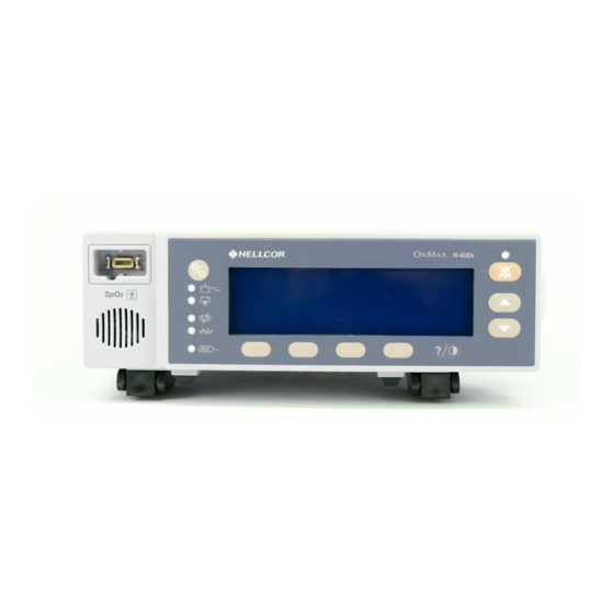
Page 16: Front Panel
General Introduction Front Panel Figure 2. OxiMax N-600x Pulse Oximeter Front Panel Table 2. List of Front Panel Components Sensor Port ADJUST UP & DOWN Keys Low Battery Indicator Pulse Rate (BPM) Upper Limit Value AC Power Indicator Pulse Rate (BPM) Lower Limit Value ON/STANDBY Key Neonate Mode Icon Battery Fuel Gauge... -
Page 17: Oximeter Visual Indicators
Front Panel messages from the display. It lights continuously when an audible alarm has been silenced. It flashes when the alarm silence duration has been set to OFF. WARNING Pressing ALARM SILENCE will keep ALL alarms from sounding for the alarm silence duration period. - Page 18 3 resulting in fewer alarms. The rate at which the SPD icon fills depends on the SPD sensitivity setting. To explore activation, contact Nellcor’s Technical Services Department at 1.800.635.5267 or your local Nellcor representative. To use the feature, reference the N-600x Operator’s Manual.
-
Page 19: Monitoring Values
Front Panel SatSeconds Icon—The SatSeconds feature provides alarm management for mild or brief SpO limit violations. When the SatSeconds feature is enabled, the SatSeconds circle icon fills in the clockwise direction as the SatSeconds alarm management system detects SpO readings outside of the limit setting. The SatSeconds icon empties in counterclockwise direction when SpO readings are within limits. -
Page 20: Audible Indicators
General Introduction Audible Indicators Audible indicators include pitched tones and beeps. Caregivers may choose to silence alarms by pressing the ALARM SILENCE key. WARNING Pressing ALARM SILENCE will keep ALL alarms from sounding for the alarm silence duration period. Caution Should the caregiver fail to clear a primary audible alarm within two (2) minutes, a secondary alarm with a unique pitch sounds. -
Page 21: Rear Panel
Rear Panel Rear Panel Figure 3. OxiMax N-600x Pulse Oximeter Rear Panel Table 4. Rear Panel Components Equipotential Terminal (Ground) AC Power Connector Data Port Connector Fuse Holder Supply Voltage Selector Switch Rear Panel Symbols and Descriptions Warning! See Instructions for Use Fuse replacement Equipotential terminal (ground) Date of manufacture... -
Page 22: Oximeter Features
General Introduction Oximeter Features OxiMax SPD™ Alert Feature The OxiMax SPD™ Alert (SPD) feature detects patterns of desaturation in adults that are indicative of repetitive reductions in airflow through a patient's upper airway into the lungs. Relative reductions in a patient's minute ventilation over a period of time may cause a progressive drop in alveolar partial pressure of oxygen, leading to arterial desaturation. - Page 23 Oximeter Features monitors both degree and duration of desaturation as an index of desaturation severity. Thus, the SatSeconds feature helps distinguish clinically significant events from minor and brief desaturations that may result in nuisance alarms. Figure 5. First Event: No SatSeconds Alarm 10030881 Rev.
- Page 24 General Introduction Figure 6. Second Event: No SatSeconds Alarm 10030881 Rev. B 12-2008 Service Manual...
- Page 25 Oximeter Features Figure 7. Third Event: Triggers SatSeconds Alarm The SatSeconds “Safety Net” is for patients with saturation levels frequently below the limit, but not staying below the limit long enough for the SatSeconds time setting to be reached. When three or more limit violations occur within 60 seconds, an alarm sounds even if the SatSeconds time setting has not been reached.
-
Page 26: Pulse Rate Delay Alarm Management Feature
General Introduction Pulse Rate Delay Alarm Management Feature The oximeter monitors pulse rate by determining the number of pleth waves over unit time. With traditional alarm management, upper and lower alarm limits are set for monitoring pulse rate. When the pulse rate fluctuates near an alarm limit, the alarm sounds each time it violates an alarm limit. -
Page 27: Plethysmographic (Pleth) Display
Oximeter Display View Options Plethysmographic (Pleth) Display Figure 9. Pleth Display View Use this display view for visual monitoring information in waveform. The plethysmographic (pleth) display includes a “wiper bar” plethysmographic waveform, menu bar, and current measured SpO and pulse rate, upper and lower limit settings. - Page 28 General Introduction data plots, current measured SpO and pulse rates. It also includes a battery fuel gauge if running on battery power. Each time the oximeter detects a pulse, the heart icon flashes. If enabled, SatSeconds and SPD icons display. For more information, reference the N-600x Operator’s Manual.
-
Page 29: Chapter 3. Product Specifications
3 Product Specifications Overview This section contains OxiMax N-600x™ pulse oximeter physical and operational specifications. Ensure all product requirements are met prior to installation of the oximeter. Physical Characteristics 5.8 lbs. (2.6 kg) Weight 3.3 in. x 10.4 in. x 6.8 in. (8.4 cm x 26.4 cm x 17.3 cm) Dimensions Electrical Requirements Power... -
Page 30: Rating Of Nurse Call Relay
Product Specifications Rating of Nurse Call Relay 30 VAC or VDC (polarity is not important) Maximum Input Voltage 120 mA continuous (peak 300 mA @ 100 ms) Load Current 26.5 ohms to 50.5 ohms (40.5 ohms typical) during alarms Minimum Resistance Isolated Ground Ground Reference 1500 Volts... -
Page 31: Oximax™ Pulse Oximetry Sensors
Performance Specifications OxiMax™ Pulse Oximetry Sensors Pulse Oximetry Sensor Accuracy Table 5. Oxygen Saturation Accuracy LoSAT™ Range Standard Saturation Range Sensor Model Type 60% to 80% 70% to 100% MAX-A, MAX-AL ± 3.0 digits ± 2.0 digits MAX-N ± 3.0 digits ±... -
Page 32: Product Compliance
Product Specifications OxiMax Pulse Oximetry Sensor Operating Range Approximately 660 nm Red Light Wavelength Approximately 900 nm Infrared Light Wavelength Less than 15 mW Optical Output Power Product Compliance Product Standards for Compliance ISO 9919:2005 EN ISO 9919: 2005 Product Safety Standards IEC 60601-1: 1988 + A1: 1991 + A2: 1995 EN 60601-1: 1990 + A11: 1993 + A12: 1993 + A13: 1996 UL 60601-1 1st edition... -
Page 33: Electromagnetic Compatibility (Emc)
Manufacturer’s Declaration Electromagnetic Compatibility (EMC) Electromagnetic Emissions Table 6. Electromagnetic Emissions Emissions Test Compliance Electromagnetic Environment Guidance RF emissions Group 1 The oximeter is suitable for use in all Class B establishments. CISPR 11: 2004 Harmonic emissions Class A The oximeter is suitable for use in all establishments. - Page 34 Product Specifications Table 7. Electromagnetic Immunity Testing IEC 60601-1-2 Compliance Electromagnetic Immunity Test Test Level Level Environment Guidance Electrostatic ± 6 kV contact ± 6 kV contact Floor should be wood, discharge (ESD) concrete, or ceramic tile. If ± 8 kV air ±...
-
Page 35: Sensor And Cable Compliance
Manufacturer’s Declaration Table 8. Recommended Separation Distances Electromagnetic IEC 60601-1-2 Test Environment Immunity Test Level Compliance Level Guidance Equation for Frequency of Separation Transmitter Distance Conducted RF 3 Vrms 3 Vrms distance = 1.2 150 kHz 61000-4-6: 2006 80 MHz Radiated RF 3 V/m 3 V/m... -
Page 36: Safety Tests
Product Specifications Table 9. Cables and Sensors Item Maximum Length Cables Power cord 10.0 ft. (3 m) DOC-10 pulse oximetry cable 10.0 ft. (3 m) Software download cable, 10.0 ft. (3 m) RS-232 serial, 15 to 9 pin “D” Non-terminated cable, 10.0 ft. -
Page 37: Leakage Current
Safety Tests Leakage Current The following tables display the maximum earth and enclosure leakage current allowed, as well as patient leakage. Table 10. Earth and Enclosure Leakage Current Specifications Earth Leakage Current Neutral Condition AC Polarity Line Cord Line Cord IEC 60601-1 UL 60601-1 Normal... - Page 38 Product Specifications Table 11. Patient Applied and Patient Isolation Risk Current Patient Applied Risk Current Power Line Ground IEC 60601-1 Condition AC Line Polarity Neutral Line Cable UL 60601-1 Normal Normal Closed Closed 100 µA Single Fault Open Closed 500 µA Closed Open Normal...
-
Page 39: Chapter 4. Theory Of Operations
4 Theory of Operations Overview This section explains the theory behind OxiMax N-600x™ pulse oximeter operations. Understanding Pulse Oximetry Theoretical Principles The OxiMax N-600x pulse oximeter uses pulse oximetry to measure functional oxygen saturation in the blood. Pulse oximetry works by applying an OxiMax™ pulse oximetry sensor to a pulsating arteriolar vascular bed, such as a finger or toe. -
Page 40: Automatic Calibration
Theory of Operations absorption by pulsatile arterial blood, eliminating the effects of nonpulsatile absorbers such as tissue, bone, and venous blood. Automatic Calibration Because light absorption by hemoglobin is wavelength dependent and because the mean wavelength of LEDs varies, an oximeter must know the mean wavelength of the OxiMax pulse oximetry sensor's red LED to accurately measure SpO During monitoring, the oximeter's software selects coefficients that are appropriate for the wavelength of that individual sensor's red LED;... -
Page 41: Oximeter Features
Oximeter Features variables such as pH, temperature, the partial pressure of carbon dioxide (PCO2), and 2,3-DPG that shift the relationship between PO and SpO Figure 13. Oxyhemoglobin Dissociation Curve Oximeter Features SatSeconds™ Alarm Management Feature The oximeter monitors hemoglobin saturation with oxygen in the blood. With traditional alarm management, upper and lower alarm limits are set for monitoring levels. -
Page 42: Oximax Spd™ Alert Feature
Theory of Operations Rate Delay feature distinguishes clinically significant events from minor and brief pulse rate limit violations that result in nuisance alarms. To use the Pulse Rate Delay feature, set the traditional alarm management upper and lower pulse rate alarm limits. Then, set the Pulse Rate Delay. The Pulse Rate Delay limit controls the time the pulse rate level crosses either limit before an audible alarm sounds. -
Page 43: Functional Testers And Patient Simulators
Nellcor oximeters and/or sensors. Not all such devices, however, are adapted for use with the Nellcor OxiMax digital calibration system. While this will not affect use of the simulator for verifying system functionality, displayed SpO measurement values may differ from the setting of the test device. - Page 44 Theory of Operations 10030881 Rev. B 12-2008 Service Manual...
-
Page 45: Chapter 5. Product Overview
5 Product Overview Overview The OxiMax N-600x™ pulse oximeter relies on unique oximetry technology and design in providing hospitals, clinicians, and caregivers accurate, timely data. Oximeter Block Diagram The following block diagram shows the flow of data in the OxiMax N-600x pulse oximeter, including input and output. -
Page 46: System Board Components
Product Overview System Board Components System Board Component Overview The OxiMax N-600x pulse oximeter Main Board (PCB) consists of three (3) main components. These components provide support for data exchange and input from the clinician, technician, or caregiver during use. The three primary components are listed below. -
Page 47: User Interface (Uif)
Power • Analog outputs • Sound generation by generating the appropriate volume and frequency control settings for the speaker circuitry • Monitoring and controlling oximeter power • Communicating with the real-time clock (RTC) and electrically-erasable-programmable-read-only-memory (EEPROM) • Trend data collection and storage Static random access memory (RAM) and FLASH read-only memory (ROM) are provided for the microprocessor on the PCB. -
Page 48: Pulse Oximetry Sensors And Cables
Product Overview Pulse Oximetry Sensors and Cables Before attaching any of the various Nellcor approved OxiMax pulse oximetry sensors to the oximeter, refer to the individual OxiMax Sensor's Directions for Use (DFU) and the OxiMax Sensor Accuracy Grid (SAG). Also reference the Product Specifications chapter for Pulse Oximetry Sensor Accuracy, page 31. -
Page 49: Chapter 6. Setting Up The Oximeter
Ensure that the speaker is clear of any obstruction. Failure to do so could result in an inaudible alarm tone. WARNING Disconnect the oximeter and Nellcor OxiMax pulse oximetry sensor from the patient during magnetic resonance imaging (MRI) scanning. Objects containing metal can become dangerous projectiles when subjected to the strong magnetic fields created by MRI equipment. -
Page 50: Connecting To An Ac Power Source
WARNING Use only the Nellcor DOC-10 pulse oximetry cable with the OxiMax N-600x pulse oximeter. Use of another pulse oximetry cable will have an adverse effect on performance. Do not attach any cable that is intended for computer use to the OxiMax N-600x pulse oximeter sensor port. -
Page 51: Using Battery Power
Using Battery Power Figure 15. Back Panel Supply Voltage Selector and Power Connector 2. Plug the female connector end of the power cord into the power connector on the rear of the oximeter. 3. Plug the male connector of the power cord into a properly grounded AC outlet. 4. - Page 52 Setting Up the Oximeter Power is supplied to the OxiMax N-600x pulse oximeter either from an AC connection (100-120 or 200-240 VAC) or from a 6-volt, 4 ampere-hour battery. The oximeter internal battery can be used to power the oximeter during transport or when AC power is not available.
-
Page 53: Connecting An Oximax™ Pulse Oximetry Sensor
Note: Whenever the oximeter is connected to AC power source, the battery is being charged. Nellcor recommends the oximeter remain connected to an AC power source when not in use. This ensures full battery power when the oximeter is needed. -
Page 54: Reducing Emi (Electromagnetic Interference)
Setting Up the Oximeter 5. Apply the sensor to the patient. Be sure to read the Directions for Use accompanying the sensor. 6. When the oximeter detects a valid pulse, it enters the monitoring mode and displays real-time patient data. Reducing EMI (Electromagnetic Interference) Caution This device has been tested and found to comply with the limits for medical devices related... -
Page 55: Chapter 7. Operating The Oximeter
Schedule regular maintenance and safety checks with a qualified service technician every 24 months. In the case of mechanical or functional damage, contact Nellcor’s Technical Services Department at 1.800.635.5267 or your local Nellcor representative. -
Page 56: Low Battery Indicator
Have a qualified service technician replace the internal battery every 24 months. The lead acid battery is recyclable. Do not dispose of the battery by placing it in the regular trash. Dispose of the battery in accordance with local guidelines or contact Nellcor’s Technical Services department to arrange for disposal. -
Page 57: Powering The Oximeter
Power Prerequisites Caution If any indicator or display element does not light when the pulse oximeter is turned on, do not use the oximeter. Instead, contact qualified service personnel, your local Nellcor representative, or Nellcor’s Technical Services Department. Caution During POST (immediately after power-up), confirm that all indicators light, all display segments turn on, and the pulse oximeter speaker sounds a sequence of three ascending tones. - Page 58 Within ten seconds, all LEDs, pixels and the backlight should illuminate. b. The indicators should remain lit for two seconds. c. The LCD display should show the NELLCOR logo and the firmware version of the OxiMax N-600x pulse oximeter.
-
Page 59: Automatic Shutdown And Power Off
For more information on selecting the right pulse oximetry sensor for the specific patient and situation, see the N-600x Operator’s Manual. Consider all possible variables. If still in doubt, contact Nellcor’s Technical Services Department at 1.800.635.5267 or your local Nellcor representative. -
Page 60: Sensor Detection
WARNING Use only the Nellcor DOC-10 pulse oximetry cable with the OxiMax N-600x pulse oximeter. Use of another pulse oximetry cable will have an adverse effect on performance. Do not attach any cable that is intended for computer use to the SpO sensor port. -
Page 61: Sensor Detection Failure
Managing the Oximeter Backlight The movement of the blip bar, the plethysmographic waveform, or the flashing heart icon indicates real-time data display. The pulse beep tone is an audible indicator of the real-time patient data. Caution If the pulse beep tone does not sound with each pulse, the pulse beep volume is set to zero, the speaker is malfunctioning, or the signal is corrupt. -
Page 62: Managing The View Display
Operating the Oximeter 2. Press the ADJUST UP or ADJUST DOWNkey below the key on the ALARM SILENCE oximeter panel until the desired backlight brightness is obtained. To adjust the oximeter screen contrast 1. With the oximeter in the normal monitoring mode, press and hold the HELP/ CONTRAST softkey while pressing the ADJUST UP or ADJUST DOWN key below key on the oximeter panel until obtaining the desired contrast. -
Page 63: Managing Audible Alarms
Adjusting the Volume of Audible Tones 2. While continuing to press the ALARM SILENCE key, press and hold the ADJUST UP or ADJUST DOWN key to increase or decrease the volume. Note: Default alarm volume is seven (7). Select the appropriate value for the situation. The alarm volume adjusts up to ten (10) and down to one (1). -
Page 64: Using Oximeter Softkey Menus
Operating the Oximeter 1. With the oximeter in the normal monitoring mode, press the ALARM SILENCE key until the alarm silence duration setting displays. 2. While pressing the ALARM SILENCE key, press and hold the ADJUST UP key until OFF displays. Release both keys. Note: Once audible alarms are disabled, the orange LED above the ALARM SILENCE key lights to indicate the disabled alarm state. - Page 65 Using Oximeter Softkey Menus Common Menu Options 1. BACK softkey— Return to the previous menu level without exiting the selected menu area entirely. 2. NEXT softkey—Proceed to the next screen of menu options for that menu set. 3. EXIT softkey—Exit to the main menu or press BACK until you reach an EXIT menu option.
- Page 66 Operating the Oximeter softkey—Use this softkey to set upper and lower limits for neonates. Scroll through each limit setting option using the SELECT softkey until you reach the limit value you wish to change. Change the value by pressing the ADJUST UP or ADJUST DOWN key below the key on the oximeter panel until you ALARM SILENCE...
- Page 67 Using Oximeter Softkey Menus TREND Menu Choose the type of trend data to view by selecting trend data from the oximeter (MONITR) or trend data from the pulse oximetry sensor (SENSOR) in the Trend menu. 1. MONITR Menu—Isolate oxygenation (SpO ) or pulse (PULSE) trend data or view them both together (DUAL) for a specified length of time.
- Page 68 3. CLOCK Menu—Access to set the clock, both date and time. WARNING The pulse oximetry sensor extrapolates from the date and time provided by the Nellcor OxiMax N-600x pulse oximeter when recording the sensor event record to the sensor. The accuracy of the date/time is determined by the date/time setting of the pulse oximeter.
- Page 69 Using Oximeter Softkey Menus a record-enabled sensor to keep the date and time consistent for as long as the sensor remains connected. Since a sensor with sensor event record data can be transported from one oximeter to another, having discrepancies in the date/time between oximeters and the sensor event record data will affect the order in which the sensor event record data appear.
- Page 70 Operating the Oximeter To change the displayed language setting 1. With the oximeter in the normal monitoring mode, press the SETUP softkey. 2. Press the NEXT softkey. 3. Press the LANG softkey. Figure 28. Displayed Language Selection Screen 4. Use the ADJUST UP or ADJUST DOWN keys below the ALARM SILENCE key on the oximeter panel to select the desired language.
- Page 71 Using Oximeter Softkey Menus 2. NCALL Menu—From the SETUP menu, press the NEXT softkey twice so the NCALL (Nurse Call) menu option is available. Set voltage from +5 VDC to +12 VDC using Norm + or set voltage from -5 VDC to -12 VDC using Norm- when there is no audible alarm.
-
Page 72: Adjusting The Factory Default Settings
Operating the Oximeter Note: When the oximeter is in the FAST response mode, the oximeter may produce more SpO The response mode, however, may impact the pulse rate alarms than expected. alarm behavior ALARM SILENCE 4. Use the ADJUST UP or ADJUST DOWN keys below the key on the oximeter panel to select the desired response mode. - Page 73 Using Oximeter Softkey Menus An attempt to save either of these values as default results in an invalid tone. These limits can be adjusted lower for the current patient, but return to power-on defaults at power-off. Note: The SPD feature automatically sets the SatSeconds value to 100. 10030881 Rev.
- Page 74 Operating the Oximeter Changing Adult and Neonate Default Settings Table 14. Adult and Neonate Default Settings Adult Neonate Option Default Settings Default Settings %SpO Lower Alarm Limit %SpO Upper Alarm Limit 100% Alarm Silence Duration 60 Seconds Alarm Silence Duration OFF Setting Disabled Alarm Silence Reminder Enabled...
- Page 75 Using Oximeter Softkey Menus To set adult or neonatal modes WARNING Supplemental oxygen will attenuate patterns of desaturation. A patient’s respiratory compromise can be proportionally more severe before patterns appear in the saturation trend. Remain vigilant when monitoring a patient on supplemental oxygen. WARNING The SPD feature is for use with adults patients only.
- Page 76 Operating the Oximeter value for a particular patient in the limits screen. These values return to the factory or institutional default values after power cycle. Figure 32. Setting Adult Limits Screen To set limits To adjust the upper and lower saturation and pulse rate limits, select the Adult or Neonate Limit display.
-
Page 77: Using The Oximax Spd™ Alert Feature
Using Oximeter Softkey Menus 5. Repeat steps as necessary to complete the alarm limits setup. 6. Wait for the display to time-out to accept the changes or press the EXIT softkey to close the display and return to the normal monitoring mode. Using the OxiMax SPD™... -
Page 78: Using The Pulse Rate Delay Alarm Management Feature
Operating the Oximeter Using the Pulse Rate Delay Alarm Management Feature To set the alarm delay 1. With the oximeter in the normal monitoring mode, press the LIMITS softkey. 2. Press SELECT softkey until highlighting the alarm delay setting, highlighting the default setting of OFF. -
Page 79: Chapter 8. Managing The Data Port
8 Managing the Data Port Managing Oximeter Trend Data Reference the N-600x Operator’s Manual for more information about displaying and reading patient trend data. Data Port Connectivity Overview Use the data port on the back of the OxiMax N-600x™ pulse oximeter to output patient data by connecting the oximeter to a PC or serial printer. - Page 80 Managing the Data Port Caution Do not create sharp bends in the cable, as this may tear or break the shielding. No hardware flow control is used. However, support exists for XON/XOFF flow control in ASCII mode. Data Port Pinouts WARNING If the serial port, analog outputs, or nurse call lines are shorted, remote communication may be lost.
-
Page 81: Data Port Communications
1. Dump Instrument Info—Prints or displays single line of oximeter data, including the oximeter software version, CRC number, and total operating time. Information useful to Nellcor’s personnel. 2. Set Date and Time—When the oximeter ships from the factory, the date and time are set to the local factory time zone. - Page 82 Status Figure 39. Sample Trend Dump 4. Dump Error Log—Intended for Nellcor’s personnel to obtain or view information from memory that includes instrument type, software revision level, printout type, time of printout, operating time of the recorded error, error number, task number, address, and count.
-
Page 83: Accessing Data Using The Comm Port And A Computer
Data Port Connectivity 5. Press the ADJUST UP or ADJUST DOWN softkeys to select the desired protocol. Protocol options for the OxiMax N-600x pulse oximeter differ from those of the oximeter with the SPD feature activated. The factory default protocol is ASCII. See Communication Protocol Compatibility and Output, page 83. -
Page 84: Configuring The Data Port Interface
Obtain printouts or patient data by connecting an appropriate RS-232 cable to the data port on the back of the OxiMax N-600x pulse oximeter and communicating with a Nellcor Oxinet™ III monitoring system or personal computer. The data port also provides analog signals representing SpO , pulse rate, and pulse amplitude, as well as providing a remote nurse call function. - Page 85 • ASCII used for printouts and Oxinet III output • CLINICAL intended for Nellcor use only • PHILIPS interfaces the OxiMax N-600x pulse oximeter with a Philips monitor • SPDout used for faster communication baud rates Note: Setting the communication protocol automatically sets the communication baud rate.
-
Page 86: Managing The Data Port
The protocol settings must be set to ASCII MODE for printing text data. To print trend data 1. With the oximeter in the normal monitoring mode, connect the serial printer to the oximeter’s data port connector, using Nellcor printer cable part number 036341. Figure 41. Data Port Location 2. - Page 87 Managing the Data Port 6. Press the SELECT softkey to select PROTOCOL. Figure 42. Serial Port Setup Screen, Protocol Selection 7. Set the PROTOCOL to ASCII for text printing using the ADJUST UP or ADJUST DOWN key below the ALARM SILENCE key on the oximeter panel if the protocol is different.
- Page 88 Managing the Data Port At the end of the printout, an “Output Complete” line indicates the transmission was successful. If the “Output Complete” line is not present, ignore the data, since it may be corrupted. Figure 45. Sample ASCII Printout Real-Time Output Real-time data is continuously sent to the data port on the back of the N-600x pulse oximeter.
- Page 89 Managing the Data Port Real-Time Output Data Fields Here is an example of real-time data output. Figure 46. Sample Real-Time Data Output (SPD feature not enabled) 1. Column Headings—Every 25th line of the data output consists of a column heading. A column heading appears whenever the value within a column heading changes.
- Page 90 Managing the Data Port 3. Firmware Version—The next data field displays the firmware level (Version 2.0.4.0) and a firmware verification number (CRC: XXXX). Neither of these numbers should change during normal operation. Figure 49. Location of Firmware Version in Column Headings Note: firm The numbers may change if the oximeter is serviced and receives a...
- Page 91 Managing the Data Port 8. Patient data Presented in the chart from left to right. — - Time the patient data was recorded - Current SpO value - Current Pulse Rate (BPM) - Current Pulse Amplitude (PA) - Operating status of the oximeter a.
- Page 92 SPD Alarm Type—Visual alarm only or both audio and visual SPD alarms c. SPD Index—The Time column displays the SPD Index, which ranges from a value of 0 to 31. Used by Nellcor staff. 10030881 Rev. B 12-2008 Service Manual...
-
Page 93: Using The Nurse Call Interface
Using the Nurse Call Interface Using the Nurse Call Interface Nurse Call Feature WARNING Do not use the nurse call feature as the primary source of alarm notification. The audible and visual alarms of the pulse oximeter, used in conjunction with clinical signs and symptoms, are the primary sources for notifying medical personnel that an alarm condition exists. -
Page 94: Setting Nurse Call Rs-232 Polarity
Managing the Data Port common, pin 7 is normally open, and pin 8 is normally closed. See Rating of Nurse Call Relay, page 30 for ratings. Table 18. Nurse Call Relay Pin States No Alarm or Alarm Silenced Audible Alarm Oximeter Off 7 NO Open... - Page 95 Calculating the Analog Voltage Output holds that point for 15 seconds. It increases to 1.0 VDC and holds that value for 15 seconds. The third part of the calibration signal is a stair step signal. The stair step signal, begins at 0.0 VDC and increases up to 1.0 VDC in 0.1 VDC increments, each held for one (1) second.
- Page 96 Managing the Data Port 10030881 Rev. B 12-2008 Service Manual...
-
Page 97: Chapter 9. Performance Considerations
9 Performance Considerations Overview WARNING Pulse oximetry readings and pulse signals can be affected by certain ambient environmental conditions, OxiMax pulse oximetry sensor application errors, and certain patient conditions. See the appropriate sections of the manual for specific safety information. •... -
Page 98: Oximetry Considerations
OxiMax pulse oximetry sensor. Inspect the sensor site as directed in the Directions for Use. WARNING Use only Nellcor-approved OxiMax pulse oximetry sensors and pulse oximetry cables when connecting to the OxiMax sensor connector. Connecting any other cable or sensor influences accuracy of sensor data, which may lead to adverse results. -
Page 99: Inaccurate Sensor Measurement Conditions
OxiMax™ Pulse Oximetry Sensor Performance Considerations Inaccurate Sensor Measurement Conditions A variety of conditions can cause inaccurate sensor measurements. • Incorrect application of the OxiMax pulse oximetry sensor • Placement of the OxiMax pulse oximetry sensor on an extremity with a blood pressure cuff, arterial catheter, or intravascular line •... - Page 100 Performance Considerations vasoconstriction. Max-Fast pulse oximetry sensors work particularly well on supine patients and mechanically ventilated patients. During low perfusion conditions, Max-Fast pulse oximetry sensors reflect changes to the SpO up to 60 seconds earlier than digit sensors. If the Max-Fast pulse oximetry sensor is not available, consider using the OxiMax™...
-
Page 101: Chapter 10. Oximeter Preventive Maintenance
• Inspect the equipment for mechanical and functional damage or deterioration. • Inspect the safety relevant labels for legibility. Contact Nellcor Technical Services, 1.800.635.5267, if labels are damaged or illegible. • Inspect the internal fuse (F3) for proper value and rating. - Page 102 Oximeter Preventive Maintenance To perform a baseline functional check: 1. Perform the electrical safety tests detailed in Modifying and Testing the Oximeter, page 103. If the unit fails the tests, refer to Ordering Oximeter Spare Parts, page 161. 2. Inspect the external fuses for proper value and rating (F1 + F2 = 0.5 amp, 250 volts).
-
Page 103: Chapter 11. Modifying And Testing The Oximeter
Only qualified service personnel should open the oximeter housing, remove and replace components, or make adjustments. If your medical facility does not have a qualified service technician, please contact Nellcor’s Technical Services or your local Nellcor representative. Setting Institutional Defaults (Sample) Change power-on default values to institutional power-on default values using the oximeter’s service mode. - Page 104 Modifying and Testing the Oximeter Table 19. Institutional Default Settings Parameter Possible Setting Sensor Adjust Enable Yes/No Nurse Call Priority RS-232 Normally high, normally low Data Port Mode ASCII, CLINICAL, PHILIPS,SPDout Available selections depend on firmware version. Data Port Baud Rate 2400, 9600, 19200 To set institutional defaults: 1.
-
Page 105: Performance Verification
Data interface cable RS-232 cable (optional) Stop watch Manual or electronic Nellcor model SRC-MAX functional oximetry tester Provides testing for DigiCal compatible oximeters 9-pin to 15-pin D-connector with all pins shorted together Provides testing for Service Function Menus, page 130 10030881 Rev. -
Page 106: Safety Testing Standards
Modifying and Testing the Oximeter Safety Testing Standards The OxiMax N-600x pulse oximeter safety tests are performed in accordance with and meet the following standards. Also, see Product Safety Standards, page 32. • IEC 60601-1: 1988 + A1: 1991 + A2: 1995 •... -
Page 107: Performance Tests
Performance Tests Note: This section uses Nellcor factory defaults. If the institution or caregiver using the oximeter customized the defaults, the OxiMax N-600x pulse oximeter displays those customized values. See the RESET option of the PARAM (Parameters) Softkey Menu, page 132 to restore Nellcor factory defaults. - Page 108 Modifying and Testing the Oximeter Limit for %SpO2 indicates an alarm limit of “100” or the value set by the institution or caregiver as the default setting. Figure 65. Adult Limits Default Settings 4. Press and hold the ADJUST DOWN button. Verify the selected number for %SpO2 Upper Alarm Limit decreases to a minimum of “86.
- Page 109 Performance Tests 10. Press the SELECT softkey. Verify the selected Pulse Rate Lower Alarm Limit display indicates an alarm limit of “40. ” 11. Press and hold the ADJUST DOWN button. Verify the selected Pulse Rate Lower Alarm. 12. Verify the limit display decreases to a minimum of “30. ” Figure 68.
-
Page 110: Operational Setup
Modifying and Testing the Oximeter 8. Press the ADJUST UP button repeatedly until the SPD alarm threshold cycles from 2 to 3, from 3 to OFF, and back to 1. Figure 70. Testing Saturation Pattern Detection Thresholds 9. Press the SELECT softkey three times. Confirm the Pulse Rate Delay feature is selected. 10. - Page 111 Performance Tests Alarms and Alarm Silence Figure 72. SpO Sensor Port To adjust the alarms and alarm silence options: 1. Connect the DOC-10 pulse oximetry cable to the oximeter’s SpO Sensor Port. 2. Connect the OxiMax DS-100A sensor to the DOC-10 cable, then to a finger. 3.
- Page 112 Modifying and Testing the Oximeter 11. Confirm the following oximeter results: a. The waveform tracks the pulse rate. b. The Pulse Tone is audible. c. The SpO and pulse rate are flashing in the %SpO and BPM displays. d. The Audible Alarm sounds, indicating both parameters have violated the alarm limits. 12.
- Page 113 Performance Tests 17. Press the ADJUST UP button. Verify the displays indicate 60 SEC, 90 SEC, 120 SEC, and OFF. Release the ADJUST UP button when the display indicates “OFF. ” 18. Press and release the ALARM SILENCE button. Verify the oximeter’s ALARM SILENCE indicator flashes.
- Page 114 Modifying and Testing the Oximeter 2. While pressing the ALARM SILENCE button, press the ADJUST DOWN button until the alarm volume setting displays Vol 1. Verify the volume of the alarm decreases. Figure 78. ALARM VOLUME setting of 1 3. Continue pressing the ALARM SILENCE button. Press the ADJUST UP button to increase the alarm volume setting to a maximum value of 10.
-
Page 115: Overall Performance Check
Performance Tests To set the analog output settings: 1. Connect the negative lead of a voltmeter to pin 10 and the positive to lead pin 6 of the Data Port Connector on the back of the oximeter. 2. Press the SETUP softkey. 3. - Page 116 Modifying and Testing the Oximeter LED Excitation Test The LED Excitation Test utilizes normal system components to test circuit operation. Use a OxiMax™ Max-A pulse oximetry sensor to examine LED intensity control. The test uses the red sensor LED to verify intensity modulation controlled by the LED intensity control circuit.
-
Page 117: Pulse Oximetry Functional Tests
30 seconds. Verify the oxygen saturation and pulse rate values are reasonable for the subject. Pulse Oximetry Functional Tests These tests utilize the pulse oximetry functional tester (Nellcor model SRC-MAX) to verify the performance of the oximeter. 10030881 Rev. B 12-2008... - Page 118 7. Battery Low Indicator 4. Light Level Selection Button 8. Red LED Drive Indicator Overview The SRC-MAX functional tester enables qualified technicians to functionally test Nellcor OxiMax technology-based oximeters and OEM OxiMax technology-based 10030881 Rev. B 12-2008 Service Manual To Purchase, Visit Avobus.com...
- Page 119 Performance Tests oximeters. The following table provides a brief description of each test. Use the PLETH view for all functional testing. Table 22. Functional Tests Options Tests Descriptions BPM Test The test procedure simulates an OxiMax pulse oximetry sensor attached to a patient indicating a pulse rate of 60 BPM and 200 BPM.
- Page 120 Modifying and Testing the Oximeter 4. Select the PLETH view by pressing the following softkeys in sequence: SETUP, VIEW, and then PLETH to view the pleth display. Figure 84. PLETH Display with SRC-MAX tester-generated waveform a. Active audio alarm. b. Flashing %SpO indication between 73 and 77 inclusive.
- Page 121 Performance Tests 6. Press the SRC-MAX PULSE RATE selection button. The SRC-MAX PULSE RATE 60 LED lights. The oximeter registers BPM decreases and stabilizes to a value between 67 to 73 BPM inclusive. Figure 86. PLETH Display with SRC-MAX decrease to 60 BPM a.
- Page 122 Modifying and Testing the Oximeter 5. Press the SRC-MAX %SpO selection button. The SRC-MAX %SpO 90 LED lights. The oximeter displays three dashes [ - - - ] until the %SpO stabilizes at a value between 88 and 92 inclusive. Figure 88.
- Page 123 Performance Tests 4. Select the PLETH view by pressing the following softkeys in sequence: SETUP, VIEW, and then PLETH to view the pleth display. Figure 90. PLETH Display with SRC-MAX tester-generated waveform a. Active audio alarm. b. Flashing %SpO indication between 73 and 77 inclusive. c.
- Page 124 Modifying and Testing the Oximeter 6. Press the SRC-MAX PULSE RATE selection button. The SRC-MAX PULSE RATE 200 LED lights. The oximeter registers BPM increases and stabilizes to a value between 197 and 203 inclusive. Figure 92. PLETH Display with SRC-MAX increase to 200 BPM with modulation a.
- Page 125 Performance Tests 8. Press the SRC-MAX %SpO selection button. The SRC-MAX %SpO 90 LED lights. The oximeter displays three [ - - - ] dashes until the %SpO stabilizes to a value between 88 and 92 inclusive. Figure 94. PLETH Display with SRC-MAX increase in %SpO of 90 with modulation a.
- Page 126 Modifying and Testing the Oximeter 10. Press the SRC-MAX MODULATION selection button. The SRC-MAX MODULATION LED lights. The oximeter pulse amplitude waveform decreases in amplitude. Figure 96. PLETH Display with SRC-MAX decrease in modulation a. Active audio alarm. b. Flashing %SpO indication between 73 and 77 inclusive.
- Page 127 Performance Tests 5. Press the SRC-MAX LIGHT LEVEL selection button. The SRC-MAX LIGHT LEVEL LED lights. The oximeter pulse amplitude waveform initially flatlines and stabilizes at the same amplitude. Figure 98. PLETH Display with SRC-MAX increase in light Note: Flat-lining is the only indication of a light change at the measurement site. If the oximeter recovers and displays normally, this is an indication of proper operation with light changes.
- Page 128 Modifying and Testing the Oximeter 7. Press the SRC-MAX PULSE RATE selection button. The SRC-MAX PULSE RATE 60 LED lights. The oximeter registers the pulse rate decreases and stabilizes at a value between 57 and 63 inclusive. Figure 100. PLETH Display with SRC-MAX decrease to 60 BPM with high light condition a.
- Page 129 Performance Tests 9. Press the SRC-MAX %SpO selection button. The SRC-MAX %SpO 75 LED lights. The oximeter displays three dashes [ - - - ] and stabilizes at a value between 73 and 77 inclusive. Figure 102. PLETH Display with SRC-MAX decrease in %SpO of 75 with high light condition a.
-
Page 130: Setting Nurse Call
Service Function Menus Service functions can be used to select institutional defaults and to access information about the patient or oximeter. Only a trained Nellcor Customer Service Technician, qualified service technician, or clinical engineer should access many of the items available through the service functions. - Page 131 Performance Tests All service function menus are accessible when the DOC-10 pulse oximetry cable is disconnected from the oximeter. Disconnect the DOC-10 pulse oximetry cable from the oximeter or disconnect the OxiMax pulse oximetry sensor from the DOC-10 pulse oximetry cable. Note: Service function menus are only accessible from the Main Menu display.
- Page 132 Modifying and Testing the Oximeter 3. NEXT Menu—Access the Download, Alarms, and Battery submenus. PARAM (Parameters) Softkey Menu By pressing the PARAM softkey, the softkey menu options change. These options can be accessed when a pulse oximetry cable is connected to the oximeter. Figure 106.
- Page 133 If the Output Complete statement does not print at the end of the printout, consider the data invalid. 2. ERRLOG Softkey—Used only by Nellcor’s Customer Service Engineering, a qualified service technician, or a clinical engineer. Selecting the ERRLOG softkey provides a list of all the errors recorded in memory.
- Page 134 Modifying and Testing the Oximeter NEXT Softkey Submenus Figure 108. DOWNLD and ALARMS Service Menu Options 1. DOWNLD Softkey—Used to display the revision of the Boot Code. To exit DOWNLD, cycle power to the oximeter by pressing the ON/STANDBY button. Consult the Directions for Use (DFU) provided with any downloads or upgrades to the FLASH firmware.
- Page 135 TREND key), or to select VIS for visual only SPD alarms (flashing TREND key only). Figure 110. SPD Service Menu Options g. Press the BACK softkey. 3. BATTRY Option—Reserved for Nellcor use only. Do not use. Figure 111. BATTRY Service Menu Options 10030881 Rev. B 12-2008 Service Manual...
- Page 136 Modifying and Testing the Oximeter 10030881 Rev. B 12-2008 Service Manual To Purchase, Visit Avobus.com or call 1-800-674-3655...
-
Page 137: Chapter 12. Troubleshooting
WARNING Only qualified service personnel should open the oximeter housing, remove and replace components, or make adjustments. If your medical facility does not have a qualified service technician, please contact Nellcor’s Technical Services or your local Nellcor representative. WARNING Do not spray, pour, or spill any liquid on the OxiMax N-600x pulse oximeter, its accessories, connectors, switches, or openings in the chassis. - Page 138 Troubleshooting To access on-screen help topics Access multiple on-screen help topics and select a specific topic to view. Follow the example described below to access the SatSeconds help topic. 1. From the Main menu, press the HELP/CONTRAST key. The HELP MAIN window appears.
- Page 139 Help and Support 4. From page (2 / 2) of the HELP MAIN window, press ADJUST DOWN to select PRDELAY and then press SHOW. The HELP PRDELAY window appears.The SatSeconds help topic contains a total of two (2) consecutive help windows. Press the NEXT softkey to scroll through each window of the selected help topic for the following information: “Pulse Rate Alarm Delay can reduce alarms reported for brief pulse rate limit...
-
Page 140: Problem Resolution
Troubleshooting 4. Press SHOW. The HELP LIMITS SELECT window appears. Figure 115. Select Limits Help Screen 5. Press BACK. 6. Press ADJUST DOWN t to highlight NEO and then press SHOW. The HELP LIMITS NEO window appears. Figure 116. Neonate Limits Help Screen 7. -
Page 141: Prompts, Error Messages, And Error Codes
Prompts, Error Messages, and Error Codes symptoms an oximeter might display. Refer to the listed section for corrective actions. Table 23. Problem Categories Symptom Recommended Corrective Action See Power, page 152. Power No power using AC and/or DC power source. Fails power-on self-test. - Page 142 Troubleshooting 1. Prompts—Prompts require a response. For example, the “SAVE DEFAULTS ?” prompt requires a user response of YES or NO. Figure 118. Save Defaults Prompt Screen 2. Error messages—Error messages provide information. The SENSOR error message leaves any action to the discretion of the user. DISCONNECTED Advisory messages appear as centered text at the bottom of the screen.
- Page 143 Prompts, Error Messages, and Error Codes Table 24. Common Prompts and Error Messages Time- Exit on out in Exit on Alarm Message secs Alarm? Silence? Displayed Resolution DATA TYPE When a blank event Clears on time-out, sensor +BPM sensor is connected disconnect, or pressing the to a oximeter with ALARM SILENCE key,...
-
Page 144: Error Codes
Troubleshooting Table 24. Common Prompts and Error Messages Time- Exit on out in Exit on Alarm Message secs Alarm? Silence? Displayed Resolution READING None When the oximeter Completely retrieve sensor TRENDS... needs more than data or select ABORT. four to six seconds to retrieve trend data from memory. - Page 145 Prompts, Error Messages, and Error Codes When an error code other than the ones listed in Table Table 25 on page 145 appears, turn the oximeter off and back on again. Cycling the power should clear the error. If the error code reappears, record it and notify service personnel. When this occurs, the unit will stop monitoring, remove all information from the screen and display the message “EEE XXX, ”...
-
Page 146: Error Codes For Non-Correctable Failures
Troubleshooting Error Codes for Non-correctable Failures Contact Nellcor’s Technical Services Department, or your local Nellcor representative should the oximeter detect a non-correctable failure. When one of the listed errors occurs, several events also occur. • The oximeter sounds a low priority alarm that cannot be silenced except by power cycling the oximeter. - Page 147 Prompts, Error Messages, and Error Codes Table 26. Error Code Listing for Non-correctable Failures Error Code Category Description 54-128 Reserved for future front end object errors. 129-171 Unexpected LPS error (LPS recovered from this error). 172-255 Reserved for future back end object errors. %SpO back end reports beginning of packet missing.
- Page 148 Troubleshooting Table 26. Error Code Listing for Non-correctable Failures Error Code Category Description Sensor trend not open. Sensor trend already open. Sensor trend Sensor trend data unavailable. All sensor trend data read. Incompatible private label. 290-511 Reserved for future back end object errors. General failure of UIF Module generic post.
- Page 149 Prompts, Error Messages, and Error Codes Table 26. Error Code Listing for Non-correctable Failures Error Code Category Description Memory corruption detected. RTOS Resource unavailable. %SpO front end reset. %SpO front end %SpO reported error. Clinical mode was exited after input was received. Comm Communication failures between software modules.
- Page 150 Troubleshooting Table 26. Error Code Listing for Non-correctable Failures Error Code Category Description Oximetry module reports internal memory buffer overflow. Oximetry module reports host reset. Oximetry module ROM/Code integrity error. Oximetry module RAM error. Oximetry module reports background self-test failed to complete in the allocated time.
- Page 151 Prompts, Error Messages, and Error Codes Table 26. Error Code Listing for Non-correctable Failures Error Code Category Description Battery charger error - instance #2. Battery charger error - instance #3. Battery charger error - instance #4. Battery charger error - instance #5. Battery charger error - instance #6.
-
Page 152: Power
Troubleshooting Power Power problems are related to AC and/or DC power issues. Use the following recommended actions to correct power problems. Table 27. Power Problems Symptom Recommended Corrective Action • Low Battery indicator Ensure the oximeter is plugged into an operational AC outlet and the AC indicator is lit. -
Page 153: Keys
Keys Keys This section relates to non-responsive keys. Table 28. Keys Problems Symptom Recommended Corrective Action • Keys do not respond when Replace the Main Board PCB. See Main Board PCB Replacement, page 179. the oximeter is turned on. • If the keys still do not work, replace the Top enclosure assembly. -
Page 154: Operational Performance
Troubleshooting Operational Performance This section relates to operational performance where no error codes display. Table 30. Operational Performance Problems Symptom Recommended Corrective Action • The Pulse Amplitude The OxiMax pulse oximetry sensor may be damaged; replace the sensor. indicator seems to indicate •... -
Page 155: Primary Speaker Failure
If an OxiMax N-600x pulse oximeter reports a primary speaker failure, do not use the oximeter longer than necessary to ensure patient safety. Contact a qualified service technician, your local Nellcor representative, or Nellcor's Technical Services Department at 1.800.635.5267 for assistance. -
Page 156: Low And Critical Battery Conditions
Troubleshooting Low and Critical Battery Conditions Table 32. Low and Critical Battery Conditions Critical State Battery Battery Power Operation -normal AC/Battery charge LED-on LOW BATTERY LED-off LOW BATTERY message-off Audible alarm-off Error code-none Effect of ALARM SILENCE key-normal Shutdown-N/A -normal AC/Battery charge LED-off LOW BATTERY LED-off LOW BATTERY message-off... - Page 157 55. If the battery does not charge, notify a service personnel to replace the battery. • One or more display elements or Do not use the oximeter; contact qualified service personnel or your local Nellcor representative. indicators do not light during the power-on self-test (POST). • The oximeter is operating on battery Ensure the supply voltage selector switch is set to the proper voltage.
- Page 158 If the error code is still present, turn the unit off and allow it to continue to charge. If the oximeter has been charged for 30 minutes and the error code persists, contact Nellcor’s Technical Services Department at 1.800.635.5267 or your local Nellcor representative. See Error Codes for Non-correctable Failures, page 146 10030881 Rev. B 12-2008...
-
Page 159: Obtaining Technical Assistance
For technical information and assistance, to order parts, or to order an N-600x Service Manual, contact Nellcor’s Technical Services Department at1.800.635.5267 or your local Nellcor representative. The N-600x Service Manual includes block diagrams, schematics, and a parts list required by qualified personnel when servicing the oximeter. - Page 160 Troubleshooting 10030881 Rev. B 12-2008 Service Manual To Purchase, Visit Avobus.com or call 1-800-674-3655...
-
Page 161: Chapter 13. Ordering Oximeter Spare Parts
Ordering Replacement Parts Nellcor's Technical Services provides technical assistance information and replacement parts. Contact Nellcor or your local Nellcor representative to obtain replacement parts. Refer to parts by the part names and part numbers. A listing of the spare parts and accessories for the OxiMax N-600x pulse oximeter is on the Internet at: http://www.nellcor.com... -
Page 162: Spare Parts List
Ordering Oximeter Spare Parts Spare Parts List The figure below shows the OxiMax N-600x pulse oximeter expanded view. See the Spare Parts List by Call-out Number, page 163 for descriptions and part numbers. Figure 123. Exploded View POX_10042_A 10030881 Rev. B 12-2008 Service Manual... - Page 163 Spare Parts List Table 34. Spare Parts List by Call-out Number Item Description Part Number Top Enclosure with Membrane Switch 10009087 Main Board or Main PCB SP10014868 Battery Bracket 035307 Battery 640119 Display PCB SP10006091 Fuse Drawer 691500 Fuses 691032 Power Entry Module 10004406 Cooling Fan...
- Page 164 Ordering Oximeter Spare Parts Table 35. Spare Parts List by Part Number Item Part Number Description 035307 Battery Bracket 036702 Tilt Stand (not shown) 049798 Power Cord U.S.A. (not shown) 640119 Battery 691032 Fuses 691500 Fuse Drawer 901863 Power Cord U.K. (not shown) 10003713 Cooling Fan 10002385...
-
Page 165: Chapter 14. Repairing The Oximeter
WARNING Only qualified service personnel should open the oximeter housing, remove and replace components, or make adjustments. If your medical facility does not have a qualified service technician, please contact Nellcor’s Technical Services or your local Nellcor representative. WARNING Before attempting to open or disassemble the OxiMax N-600x pulse oximeter, disconnect the power cord to avoid possible injury. -
Page 166: Fuse Replacement
Repairing the Oximeter Oximeter, page 167, then proceed to replace the faulty PCB with a known good PCB. Verify the symptom disappears and ensure the oximeter passes all performance tests. If the symptom persists, swap the replacement PCB with the suspected malfunctioning PCB (the original PCB installed when you started troubleshooting) and continue troubleshooting. -
Page 167: Oximeter Disassembly And Reassembly
Oximeter Disassembly and Reassembly Oximeter Disassembly and Reassembly Disassembling the Oximeter Caution Observe ESD (electrostatic discharge) precautions when disassembling and reassembling the OxiMax N-600x pulse oximeter and when handling any of the components of the oximeter. Note: The battery charge procedure should be performed before oximeter repairs when possible. To disassemble the oximeter: 1. - Page 168 Repairing the Oximeter 7. Separate the oximeter’s top and bottom cases without stressing the connection harnesses between the cases. Caution To avoid stress or damage to the power supply wiring harness, ensure the top enclosure is lying flat on the work surface. 8.
-
Page 169: Reassembling The Oximeter
Oximeter Disassembly and Reassembly Reassembling the Oximeter To reassemble the oximeter: 1. Connect the oximeter’s power supply harness to J200 (3) on the Main Board PCB. 2. Place the oximeter’s top enclosure over the bottom case, being careful to align the Display PCB, Power Entry Module, and the fan with the slots in the oximeter casing. -
Page 170: Battery Replacement
Caution The lead-acid battery is recyclable. Do not dispose of the battery by placing it in the regular trash. Dispose of the battery in accordance with local guidelines or contact Nellcor’s Technical Services department to arrange for disposal. 10030881 Rev. B 12-2008... -
Page 171: Replacing The Battery
Battery Replacement Replacing the Battery To replace the old battery: 1. Follow the steps outlined in Removing the Old Battery, page 170. 2. Connect the leads to the battery. The red wire connects to the positive terminal, and the black wire connects to the negative terminal. 3. -
Page 172: Power Entry Module (Pem) Replacement
Repairing the Oximeter Power Entry Module (PEM) Replacement Removing the Power Entry Module 1. Turn the oximeter off by pressing the ON/STANDBY button. 2. Disconnect the oximeter from the AC power source and follow the steps outlined in Disassembling the Oximeter, page 167. 3. -
Page 173: Replacing The Power Entry Module
Power Entry Module (PEM) Replacement Replacing the Power Entry Module To replace the power entry module: 1. Reconnect the three power supply leads as indicated in Removing the Power Entry Module, page 172. 2. Install the PEM in the bottom case with the fuse drawer facing down. A tab in the bottom case holds the PEM in place. -
Page 174: Power Supply Replacement
Repairing the Oximeter Power Supply Replacement Removing the Power Supply To remove the power supply: 1. Turn the oximeter off by pressing the ON/STANDBY button. 2. Disconnect the oximeter from the AC power source and follow the steps outlined in Disassembling the Oximeter, page 167. 3. -
Page 175: Replacing The Power Supply
Power Supply Replacement Replacing the Power Supply To replace the power supply: 1. Reconnect the three leads to the PEM and the leads to the equipotential terminal and the battery, shown in Removing the Power Entry Module, Figure 128 on page 172. -
Page 176: Cooling Fan Replacement
Repairing the Oximeter Cooling Fan Replacement Removing the Cooling Fan To remove the cooling fan: 1. Turn the oximeter off by pressing the ON/STANDBY button. 2. Disconnect the oximeter from the AC power source and follow the steps outlined in Disassembling the Oximeter, page 167. 3. -
Page 177: Display Pcb Replacement
Display PCB Replacement Display PCB Replacement Removing the Display PCB WARNING The LCD panel contains toxic chemicals. Do not touch broken LCD panels. Physical contact with a broken LCD panel can result in transmission or ingestion of toxic substances. To remove the Display PCB: 1. -
Page 178: Replacing The Display Pcb
Repairing the Oximeter Table 39. Opening Oximeter Casting Figure Callouts Description Double-sided tape Display PCB Double-sided tape Display ribbon cable CCFL wires to J4 Connector on Main PCB Display ribbon cable to J7 Connector on Main PCB 4. Use a small blade screwdriver to remove the clip from either edge of J7 (7), then disconnect the Display PCB ribbon cable (5) from the connector. -
Page 179: Main Board Pcb Replacement
Main Board PCB Replacement Main Board PCB Replacement Removing the Main Board PCB To remove the Main Board PCB: 1. Turn the oximeter off by pressing the ON/STANDBY button. 2. Disconnect the oximeter from the AC power source and complete the steps outlined in Disassembling the Oximeter, page 167. -
Page 180: Replacing The Main Board Pcb
Repairing the Oximeter Replacing the Main Board PCB Caution When installing the Main Board PCB, hand-tighten the six screws (4-in lbs maximum). Overtightening could strip out the screw holes in the top case, rendering it unusable. To replace the Main Board PCB: 1. -
Page 181: Alarm Speaker Replacement
If replacing the speaker because of speaker failure, please contact Nellcor Technical Services or your local Nellcor representative. Note: Contact Nellcor Technical Services to discuss the return or disposal of the original speaker assembly. To remove the alarm speaker: 1. Turn the oximeter off by pressing the ON/STANDBY button. -
Page 182: Replacing The Alarm Speaker
Repairing the Oximeter 5. Remove the speaker by gently releasing the retaining tab and sliding the speaker assembly from its mounting. Caution Avoid using excessive force when pressing the speaker retaining tab. 6. Set aside or discard the original speaker assembly, so it will not be mixed with its replacement. -
Page 183: Top Case Assembly Replacement
Top Case Assembly Replacement Top Case Assembly Replacement Removing the Top Case Assembly To remove the top case assembly: 1. Turn the oximeter off by pressing the ON/STANDBY button. 2. Disconnect the oximeter from the AC power source and follow the steps outlined in Disassembling the Oximeter, page 167. -
Page 184: Packing The Oximeter For Shipment
Caution Pack the oximeter carefully. Failure to follow the packing instructions outlined in this section may result in loss or damage not covered by any applicable Nellcor warranty. This section describes how to return your oximeter. Contact Nellcor’s Technical Services Department or your local Nellcor representative for shipping instructions, including a Returned Goods Authorization (RGA) number. -
Page 185: Using A Generic Carton
3. Label the carton with a shipping address, return address, and RGA number, if applicable. Using a Generic Carton Caution Pack the oximeter carefully. Failure to follow the packing instructions outlined in this section may result in loss or damage not covered by any applicable Nellcor warranty. 10030881 Rev. B 12-2008 Service Manual... - Page 186 Repairing the Oximeter To repack the oximeter using a generic carton: 1. Place the oximeter in a plastic bag. 2. Locate a corrugated cardboard shipping carton with a bursting strength of at least 200 lbs. per square inch (psi). 3. Fill the bottom of the carton with at least two inches of packing material. 4.
-
Page 187: Chapter 15. Oximeter Schematics
15 Oximeter Schematics Overview This section focuses specifically on OxiMax N-600x™ pulse oximeter Main Printed schematics. Circuit Board (PCB) 1. Microprocessor, EEPROM, RTC, RESET circuitry 2. Logic Analyzer, Hard Reset, FLASH, Fast and Overlay SRAM circuitry 3. SIP/SOP Interface circuitry A 4. - Page 188 Oximeter Schematics 10030881 Rev. B 12-2008 Service Manual...
- Page 189 10030881 Rev. B 12-2008 Service Manual...
- Page 190 Oximeter Schematics 10030881 Rev. B 12-2008 Service Manual To Purchase, Visit Avobus.com or call 1-800-674-3655...
- Page 191 10030881 Rev. B 12-2008 Service Manual...
- Page 192 Oximeter Schematics 10030881 Rev. B 12-2008 Service Manual...
- Page 193 10030881 Rev. B 12-2008 Service Manual To Purchase, Visit Avobus.com or call 1-800-674-3655...
- Page 194 Oximeter Schematics 10030881 Rev. B 12-2008 Service Manual...
- Page 195 10030881 Rev. B 12-2008 Service Manual...
- Page 196 Oximeter Schematics 10030881 Rev. B 12-2008 Service Manual To Purchase, Visit Avobus.com or call 1-800-674-3655...
- Page 197 10030881 Rev. B 12-2008 Service Manual...
- Page 198 Oximeter Schematics 10030881 Rev. B 12-2008 Service Manual...
- Page 199 10030881 Rev. B 12-2008 Service Manual To Purchase, Visit Avobus.com or call 1-800-674-3655...
- Page 200 10030881 Rev. B 12-2008 Service Manual...
- Page 201 10030881 Rev. B 12-2008 Service Manual...
- Page 202 AT528 AT642 AT547 AT570 AT546 AT427 AT481 AT425 AT424 AT621 AT609 AT635 AT754 10030881 Rev. B 12-2008 Service Manual To Purchase, Visit Avobus.com or call 1-800-674-3655...
- Page 203 10030881 Rev. B 12-2008 Service Manual...
- Page 204 Oximeter Schematics 10030881 Rev. B 12-2008 Service Manual...
- Page 205 Index Connecting an OxiMax Sensor Contrast AC Power Indicator Controls Accessories on Internet Alarm Silence ADJUST CONTRAST UP/DOWN Help/Contrast Adjusting the Power-On Settings Cooling Fan Replacement Adult Default Settings Current, Leakage Adult-Pediatric Patients (Earth and Enclosure) Alarm Current, Leakage (Earth and Enclosure) Alarm Limit Display Current, Risk Alarm limits, setting...
- Page 206 Index External Fuse Removal Loss of Pulse with Signal Artifact, LM Low Battery Low Battery Indicator Factory Default Settings Feature OxiMax SPD™ Alert Main Board PCB Replacement Pulse Rate Delay Alarm Management Main Menu SatSeconds Alarm Management Manufacturer’s Declaration Fractional Saturation Measured Saturation Front Panel menu...
- Page 207 Index Param Softkey Alarm Speaker Parts List Battery Performance Considerations Cooling Fan Pulse Oximeter Display PCB Sensor Fuse Performance Tests Main Board PCB Performance Verification Power Entry Module Physical Characteristics Power Supply Pleth Display Top Case Assembly Plethysmographic Waveform Replacing the Alarm Speaker Plethysmographic Waveform Display Replacing the Cooling Fan Power Entry Module Replacement...
- Page 208 Index Troubleshooting, Low and Critical Battery Setting SatSeconds Alarm Limit Conditions Settings Lost Troubleshooting, On-Screen Help softkey Troubleshooting, Oximeter Displays Dashes menu bar Troubleshooting, Primary Speaker Failure Software Version Troubleshooting, Technical Assistance Spare Parts on Internet Turning On the Monitor Specifications Compliance Electrical...
- Page 210 ATTENTION: La loi fédérale des États-Unis stipule que ce produit ne peut être vendu que sur ordre d’un médicin. • PRECAUCIÓN: La ley federal de EE.UU. establece que este producto sólo puede venderse bajo prescripción médica. © 2008 Nellcor Puritan Bennett LLC All rights reserved. 10030881 Rev. B 12-2008 To Purchase, Visit Avobus.com...
Need help?
Do you have a question about the OXIMAX N-600X Series and is the answer not in the manual?
Questions and answers